Transcription
523 342523 127Windward II54 in Ceiling FanOwner’s ManualWindward IIVentilador de Techo de 1,37 mManual del Propietario
54” Windward IICeiling Fan by Hampton Bay(1) 30-Watt Pin-BasedCircular Bulb IncludedThank you for purchasing this Hampton Bay ceilingfan. This product has been manufactured with thehighest standards of safety and quality. The finishof this fan is weather resistant, but over time willnaturally weather and fade.Table of ContentsSafety Rules. 13-Speed Reverse Function forYear-Round Comfort and SavingsUnpacking Your Fan. 2ENERGY STAR CertifiedOperating Your Fan. 11Tri-Mount InstallationOperating Your Remote Control. 12Installing Your Fan. 3Care of Your Fan. 14Troubleshooting. 14QUESTIONS, PROBLEMS, MISSING PARTS:Before returning to your local Home Depot, please call ourCustomer Service Team at 1-877-527-0313 or visit www.homedepot.com.Specifications. 15Warranty Information. 16Please reference your SKU (523 342 white, 523 127 brushed steel)or UPC (082392 552961 white, 082392 552954 brushed steel).UL Model No. 54-WWD
READ AND SAVE THESE INSTRUCTIONS1. To reduce the risk of electric shock, insure electricity2.3.4.5.6.7.has been turned off at the circuit breaker or fuse boxbefore beginning.All wiring must be in accordance with the NationalElectrical Code ANSI/NFPA 70-1999 and local electricalcodes. Electrical installation should be performed by aqualified licensed electrician.WARNING: To reduce the risk of fire or electric shock,this fan should only be used with fan speed control part no.UC7058RYK, manufactured by Rhine Electronic Co., Ltd.or part no.: FAN-10R, manufactured by Chia Wei ElectricCo., Ltd.WARNING: To reduce the risk of shock, this fan must beinstalled with an isolation wall control/switch.CAUTION: To reduce the risk of personal injury, use onlythe screws provided with the outlet box.The outlet box and support structure must be securelymounted and capable of reliably supporting a minimum of35 pounds. Use only UL Listed outlet boxes marked “FORFAN SUPPORT.”The fan must be mounted with a minimum of 7 feetclearance from the trailing edge of the blades to the floor.TO REDUCE THE RISK OF FIRE, ELECTRIC SHOCK OR PERSONALINJURY, MOUNT TO OUTLET BOX MARKED “ACCEPTABLE FORFAN SUPPORT OF 35LBS (15.9KG) OR LESS” AND USE MOUNTINGSCREWS PROVIDED WITH THE OUTLET BOX. OUTLET BOXES COMMONLY USED FOR THE SUPPORT OF LIGHTING FIXTURES ARE NOTACCEPTABLE FOR FAN SUPPORT AND MAY NEED TO BE REPLACED.CONSULT A QUALIFIED ELECTRICIAN IF IN DOUBT.8. Do not wait for the fan to stop to press the reverse button.The fan will not reverse if the fan is not moving.9. Avoid placing objects in path of the blades.10. To avoid personal injury or damage to the fan andother items, be cautious when working around orcleaning the fan.11. Do not use water or detergents when cleaning the fan or fanblades. A dry dust cloth or lightly dampened cloth will besuitable for most cleaning.12. After making electrical connections, spliced conductorsshould be turned upward and pushed carefully up intooutlet box. The wires should be spread apart with thegrounded conductor and the equipment-groundingconductor on one side of the outlet box.13. Electrical diagrams are for reference only. Light kits that arenot packed with the fan must be UL Listed and marked suitable for use with the model fan you are installing.14. WARNING: To reduce risk of fire or electric shock, do notuse this fan with any solid-state speed control device.15. All set screws must be checked and retightened where necessary before installation.TO REDUCE THE RISK OF PERSONAL INJURY, DO NOT BEND THEBLADE BRACKETS (ALSO REFERRED TO AS (“FLANGES”) DURINGASSEMBLY OR AFTER INSTALLATION. DO NOT INSERT OBJECTS INTHE PATH OF THE BLADES.Safety Rules 1.
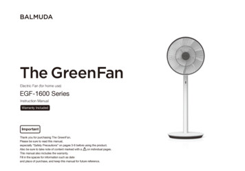
1.5.9.2.10.6.8.aabbccdd3.11.7.4.Unpack your fan and check the contents. You should have the following items:1.2.3.4.5.6.Slide-On Mounting Plate (inside Canopy)Downrod and Ball AssemblyCanopy with Canopy Ring AttachedDecorative Motor Collar CoverFan Motor AssemblyLight Kit Fitter Assembly7. Glass Shade8. Blades (5)9. Remote Batteries10. Remote Control Hand Unit & Wall Mount11. Circline Fluorescent LampIMPORTANT: THIS PRODUCT AND/OR COMPONENTS ARE COVERED BYONE OR MORE OF THE FOLLOWING U.S. PATENTS: 5,947,436; 5,988,580;5,971,573; 6,010,110; 6,010,306; 6,039,541; 6,046,416 AND OTHERPATENTS PENDING.2. Unpacking Your Fana.b.c.d.Blade Attachment Hardware(16 Screws)Electrical Hardware(3 plastic wire connectors, 1 Clevis pin,1 bolt)Close-To-Ceiling Mount Hardware(1 rubber gasket)Blade Balancing Kit
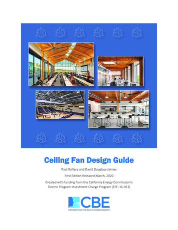
Tools RequiredPhillips screw driver, straight slot screwdriver, adjustable wrench, step ladder, andwire cutters.Figures 1, 2, and 3 are examples of differentways to mount the outlet box.Mounting OptionsFigure 3If there isn’t an existing outlet box, then readthe following instructions. Disconnect thepower by removing fuses or turning offcircuit breakers.Secure the outlet box directly to the buildingstructure. Use appropriate fasteners andbuilding materials. The outlet box and itssupport must be able to fully support themoving weight of the fan (at least 35 lbs.)Do not use plastic outlet boxes.TO REDUCE THE RISK OF FIRE, ELECTRICSHOCK OR PERSONAL INJURY, MOUNTFAN ONLY TO AN OUTLET BOX MARKEDACCEPTABLE FOR FAN SUPPORT ANDUSE THE MOUNTING SCREWS PROVIDEDWITH THE OUTLET BOX. OUTLET BOXESCOMMONLY USED FOR THE SUPPORTOF LIGHTING FIXTURES MAY NOT BEACCEPTABLE FOR FAN SUPPORT ANDMAY NEED TO BE REPLACED. CONSULT AQUALIFIED ELECTRICIAN IF IN DOUBT.Figure 1Note: You may need a longer downrod tomaintain proper blade clearance when installing on a steep, sloped ceiling. The maximumangle allowable is 30 . If the canopy touchesdownrod, remove the decorative canopybottom cover and turn the canopy 180 beforeattaching the canopy to the mounting plate.Figure 4Figure 2To hang your fan where there is an existingfixture but no ceiling joist, you may need aninstallation hanger bar as shown in Figure 4(available at your Hampton Bay retailer).Installing Your Fan 3.
Hanging the FanREMEMBER to turn off the power. Follow the steps below to hang yourfan properly.NOTE: This ceiling fan is supplied with twotypes of hanging assemblies; the standardceiling installation using the downrod withball and socket mounting, and the “close-toceiling” mounting. The “close-to-ceiling”mounting is recommended in rooms withless than 8-foot ceilings or in areas whereadditional space is desired from the floorto the fan blades. When using standarddownrod installation, the distance from theceiling to the bottom of the fan blades will beapproximately 12 inches. The “close-to-ceiling”installation reduces the distance from theceiling to the bottom of the fan blades toapproximately 8 inches.Once you have decided which ceilinginstallation you will use, proceed with thefollowing instructions. Where necessary,each section of the instructions will note thedifferent procedures to follow for the twotypes of installation.Standard Ceiling Mounting1. Remove the canopy ring from the canopyby turning the ring to the right until itunlocks (Figure 5).4.Figure 52. Remove the mounting plate from thecanopy by loosening the four screws onthe top of the canopy. Remove the twonon-slotted screws and loosen the slottedscrews. This will enable you to remove themounting plate (Figure 6).Figure 6Figure 73. Route the wires exiting the top of thefan motor through the decorative motorcollar cover then the canopy ring. Make sure 5. Align the holes at the bottom of thedownrod with the holes in the collarthe slot openings are on top. Route the wireson top of the motor housing (Figure 7).through the canopy and then through theCarefully insert the bolt through theball/downrod assembly (Figure 7).holes in the collar and downrod. Be4. Loosen, but do not remove, the set careful not to jam the bolt against thescrews on the collar on the top of thewiring inside the downrod. Insert themotor housing.
Clevis pin through the hole near theend of the bolt until it snaps into itslocked position, as noted in the circle insetof Figure 7.FAILURE TO PROPERLY INSTALL CLEVIS PINAS NOTED IN STEP 5 COULD RESULT IN FANLOOSENING AND POSSIBLY FALLING.6. Re-tighten the set screws on the collar on topof the motor housing (Figure 8).7. Proceed to “Installing the Fan” section.Tighten SetScrewFigure 8“Close-to-Ceiling” Mounting1. Remove canopy ring from the canopy byturning the ring to the right until it unlocks(Figure 5).2. Remove the mounting plate from the canopyby loosening the four screws on the top of thecanopy. Remove the two non-slotted screwsand loosen the slotted screws. This will enableyou to remove the mounting plate (Figure 6).3. Remove the decorative canopy bottom cover from the canopy by depressing the threestuds (Figure 9).Figure 94. Remove three of the six screws and lockwashers (every other one) securing the motor collar to the top of the fan motor housing(Figure 10).5. Place the rubber gasket over theremaining three screws, route the wiresexiting the top of the fan motor through thecanopy ring (make sure the slot openingsare on top), then proceed to place the ceilingcanopy over the collar at the top of the motor(Figure 11).6. Align the mounting holes with the holesin the motor and fasten, using the threescrews and lock-washers removed instep 4 (Figure 11).7. Tighten the mounting screws securely.FAILURE TO COMPLETELY TIGHTEN THETHREE SCREWS IN STEP 7 COULD RESULT INFAN LOOSENING AND POSSIBLY FALLING.Figure 10Figure 11WHEN USING THE STANDARD BALL/DOWNRODMOUNTING, THE TAB IN THE RING AT THE BOTTOM OF THE MOUNTING PLATE MUST REST INTHE GROOVE OF THE HANGER BALL. FAILURETO PROPERLY SEAT THE TAB IN THE GROOVECOULD CAUSE DAMAGE TO WIRING.5.
Dip SwitchesON12ECE34Transmitter432ECEOptionalONIn the transmitter, the dip switches areaccessible from the battery compartmentas shown in Figure A. The dip switches inthe receiver are located on top of the fanmotor assembly as shown in Figure B. Thedip switches are accessible through the topof the motor assembly. Set the switches inthe same position as the switches in thetransmitter. After the dip switch positionshave been changed and you have assuredthat they match the settings in the transmitter, turn the power on and test.Make sure the dip switches setting in thetransmitter match the receiver.When two or more fans are located neareach other you may want to have each setto a different frequency so that operationof one fan will not interfere with the other.This can be done by changing the ON/OFFposition of any one or more of a group of 4dip switches grouped together in the transmitter. The receiver, located on the top ofthe fan motor assembly, has a similar set ofdip switches which must also be changedto match the transmitter settings. Becausethe dip switches are small, please use a finepoint instrument to adjust the settings.1Setting the Dip Switches Inthe Receiver:BatteryCompartmentFigure AFigure B6.
Installing Fan tothe Outlet BoxWHEN MOUNTING THE FAN ON A SLOPEDCEILING, THE STANDARD BALL/DOWNRODMOUNTING METHOD MUST BE USED. THEMOUNTING PLATE MUST BE MOUNTED SOTHAT THE SLOT OPENINGS ARE ON THELOWER SIDE BY SLIDING THE MOUNTINGPLATE FROM THE TOP DOWN.1. Pass the 120-volt supply wires through thecenter hole in the ceiling mounting plate asshown in Figure 7.2. Install the ceiling mounting plate on theoutlet box, by sliding the mounting plateover the two screws provided with the outletbox (Figure 7). When using close-to-ceilingmounting, it is important that the mounting plate be level. If necessary, use levelingwashers (not included) between the mounting plate and the outlet box. Note that theflat side of the mounting plate is toward theoutlet box (Figure 7).3. Securely tighten the two mounting screws.4. Carefully lift the assembly up to the ceiling mounting plate. If using close-to-ceiling mounting, hang the fan on the hookprovided by utilizing one of the holes atthe outer rim of the ceiling canopy (Figure 12). If using standard mounting, seatthe hanger ball in the mounting platesocket. Make sure the tab on the mounting plate socket is properly seated inthe groove in the hanger ball.Figure 12THE HOOK AS SHOWN IN FIGURE 12 IS ONLYTO BALANCE FAN WHILE ATTACHING WIRING.FAILURE TO HANG AS SHOWN IN FIGURE 12MAY RESULT IN HOOK BREAKING, CAUSINGTHE FAN TO FALL. HOOK MUST PASS FROMINSIDE TO OUTSIDE OF CANOPY.7.
Follow the steps below to connect the fanto your household wiring. Use the wireconnecting nuts supplied with your fan. Secure the connectors with electrical tape.Make sure there are no loose strands orconnections.Step 1 Connect the fan supply (black) wire tothe black household supply wire as shown inFigure 13.Step 2 Connect the neutral fan (white) wire tothe white neutral household wire.Step 3 Connect the two green fan ground wires,located on the downrod and mounting bracket,to the household ground wire. When usingClose-to-Ceiling mounting, there is only onegreen ground wire from the ceiling mountingbracket since the ball/downrod assembly notused.8.Step 5 Turn the wire connecting nuts upwardand push the wiring into the outlet box.SUPPLY CIRCUITBlackWhiteREMEMBER to disconnect the power. Ifyou feel you do not have enough electricalwiring knowledge or experience, have your faninstalled by a licensed electrician.Step 4 After connecting the wires, spread themapart so that the green and white wires are onone side of the outlet box and the black wire ison the other side.GroundConductorBlackWhiteGreenMaking the ElectricalConnectionsGreen Ground LeadGround to DownrodTO REDUCE RISK OF FIRE OR ELECTRICSHOCK, DO NOT USE A WALL MOUNTED SOLIDSTATE SPEED CONTROL WITH THIS FAN. ITWILL PERMANENTLY DAMAGE THE ELECTRONICCIRCUITRY.EACH WIRE NUT (WIRE CONNECTOR) SUPPLIED WITH THIS FAN IS DESIGNED TO ACCEPTUP TO ONE 12 GAUGE HOUSE WIRE AND TWOWIRES FROM THE FAN. IF YOU HAVE LARGERTHAN 12 GAUGE HOUSE WIRING OR MORETHAN ONE HOUSE WIRE TO CONNECT TO THEFAN WIRING, CONSULT AN ELECTRICIAN FORTHE PROPER SIZE WIRE NUTS TO USE.Fan MotorHousingBlueBlackWhiteWhiteLight Kit AssemblyDiagram indicates light kit wiringFigure 13
Finishing the FanInstallationSTANDARD CEILING MOUNTINGWHEN USING THE STANDARD BALL/DOWNRODMOUNTING, THE TAB IN THE RING AT THE BOTTOM OF THE MOUNTING PLATE MUST REST INTHE GROOVE OF THE HANGER BALL. FAILURETO PROPERLY SEAT THE TAB IN THE GROOVECOULD CAUSE DAMAGE TO WIRING.1. Align the locking slots of the ceiling canopywith the two screws in the mounting plate.Push up to engage the slots and turn clockwise to lock in place. Immediately tightenthe two mounting screws firmly.2. Install the remaining two mountingscrews into the holes in the canopy andtighten firmly.3. Install the decorative canopy ring byaligning the ring’s slots with the screwsin the canopy. Rotate the ring counterclockwise to lock in place.4. You may now proceed to attaching thefan blades.CLOSE-TO-CEILING MOUNTING1. Carefully unhook the fan from the mounting plate and align the locking slots of theceiling canopy with the two screws in themounting plate. Push up to engage the slotsand turn clockwise to lock in place. Immediately tighten the two mounting screwsfirmly.LOCKING SLOTS OF CEILING CANOPY AREPROVIDED ONLY AS AN AID TO MOUNTING. DONOT LEAVE FAN ASSEMBLY UNATTENDED UNTIL ALL FOUR CANOPY SCREWS ARE ENGAGEDAND FIRMLY TIGHTENED.Attaching theFan Blades1. Attach the blade to the fan motor housing byinserting the blade into the slot in the sideof the fan motor housing and secure usingthe screws provided as shown in Figure 14.Start a screw into the bracket. Repeat for thetwo remaining screws.2. Tighten each screw securely.2. Install the remaining two mounting screwsinto the holes in the canopy and tightenfirmly.3. Install the decorative canopy ring by aligning the ring’s slots with the screws in thecanopy. Rotate the ring clockwise to lock inplace.4. You may now proceed to attaching the fanblades.Figure 143. Repeat steps 1, 2 & 3 for the remainingblades.9.
BLADE BALANCINGAll blades are grouped by weight. Because natural woods vary in density, the fan may wobbleeven though the blades are weight matched. Thefollowing procedure should correct most fanwobble. Check after each step.1. Check that all blade and blade bracketscrews are secure.2. Most fan wobble problems are caused whenblade levels are unequal. Check this levelby selecting a point on the ceiling abovethe tip of one of the blades. Measure froma point on the center of each blade to thepoint on the ceiling. Measure this distanceas shown in Figure 15. Rotate the fan untilthe next blade is positioned for measurement. Repeat for each blade. Measurementdeviations should within 1/8”. Run the fanfor 10 minutes.3. Use the enclosed Blade Balancing Kit if theblade wobble is still noticeable.10.Figure 15TO REDUCE THE RISK OF PERSONAL INJURY,DO NOT BEND THE BLADE HOLDERS WHILEINSTALLING, BALANCING THE BLADES, ORCLEANING THE FAN. DO NOT INSERT FOREIGNOBJECTS BETWEEN ROTATING BLADES.5. Attach the glass shade to the light kit assembly by aligning slots in top of glass shadewith ridges in light kit assembly. Push glassshade up and twist to secure (Figure 16).Installing the Light KitCAUTION - To reduce the risk of electricalshock, disconnect the electrical supply circuitto the fan before installing light kit.1. Loosen 2 opposite mounting screws on theblack bracket below the motor and removethe other two screws.2. Connect the blue wire exiting the bottom ofthe fan motor assembly with the black wirefrom the top of the light kit fitter assembly.Connect the white wire exiting the bottomof the fan motor assembly with the whitewire from the top of the light kit fitter assembly (see page 8 for diagram).3. Attach the light kit assembly to the fan motorassembly by securing with the two screwsloosened in step 1. Push light kit assemblyup to engage screw heads in slots and turn tosecure. Tighten each screw firmly.4. With the power off, install the circline lamp(MAX. 30W) provided into the light kitassembly.BlackBracketFigure 16DO NOT OVERTIGHTEN WHEN INSTALLING THEGLASS SHADE INTO THE LIGHT KIT ASSEMBLY.ALLOW THE GLASS SHADE TO COOL COMPLETELY BEFORE REMOVING.
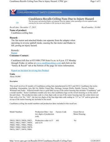
DO NOT WAIT FOR THE FAN TO STOP TO PRESSTHE REVERSE BUTTON. THE FAN WILL NOT REVERSE IF THE FAN IS NOT MOVING.Speed settings for warm or cool weatherdepend on factors such as room size, ceiling height, number of fans, and so on.The hand unit controls(forward or reverse).directionsWarm weather - (Forward) A downwardair flow creates a cooling effect as shownin Figure 17. This allows you to set yourair conditioner on a higher setting withoutaffecting your comfort.Figure 17Cool weather - (Reverse) An upward airflow moves warm air off the ceiling are asshown in Figure 18. This allows you to setyour heating unit on a lower setting without affecting your comfort.Figure 18Operating Your Fan 11.
CAUTION - This device complies with part 15of the FCC rules. Changes or modifications notexpressly approved by the manufacturer couldvoid your authority to operate this equipment.Transmitter OperationNOTE: Be sure to install1.5-volt batteries (included).4freshFan - Pressing this button steps throughthe various fan speeds “High”, “Med.”, “Low”and “Off”. The fan speed is displayed onthe LCD screen.Light - Momentarily pressing this button willturn the light on and off.For/Rev - Reverses the fan’s direction ofrotation.Fan Auto and Temp Set (Up and Down)- Pressing the Fan Auto button places the fan inautomatic control mode. In this mode the fanspeed is automatically set on “High”, “Med.”,or “Low” speed depending upon the room temperature and the user selected temperature setpoint. Press the Temp Set Up and Down buttons to select the desired room temperature. Ifthe room temperature is less than the set pointthen the fan turns off, if the room temperatureis within 3 degree F over/or equal to the setpoint then the fan will be on “Low” speed. Asthe room temperature increases the fan will automatically switch to “Med” and then “High”speed. For every 4 degree F over the set temperature, the fan will switch to the next higherspeed.Timer - Automatically turns the fan/light offafter a pre-selected amount of time. Press theTimer button followed by the Up and Downbuttons to adjust the time delay before the fan/light turns off.Light Delay - Pressing this button activates thelight delay function. The light will automatically shut off after 3 minutes.12. Operating Your Remote ControlWall Mount - Your remote control modelcomes with a holder included for the transmitterwhich can be mounted on a convenient locationon a wall. The holder will help prevent yourtransmitter from being misplaced.The remote control monitors the air temperatureto automatically control the fan speed. Ideallylocate control on an interior wall where it willaccurately read the air temperature away fromdirect sun or other heat sources.SETPOINTOFFLOWMEDHISUMMER72 F75 F71 F74 FWINTER78 F80 F77 F79 F72-75 F 75-78 F78-81 F 80-83 F76-79 F 79-82 F82-85 F 84-87 F80 F 86 F 83 F 88 F
To select C /F , press these two buttons atthe same time and hold for 3 seconds or usea ballpoint pen or small screwdriver to pressthe hole in the back of the transmitter.13.
Care of Your FanTroubleshooting1. Because of the fan’s natural movement,some connections may become loose.Check the support connections, brackets,and blade attachments twice a year. Makesure they are secure. (It is not necessary toremove fan from ceiling.)Fan will not startHere are some suggestions to help youmaintain your fan.2. Clean your fan periodically to help maintainits new appearance over the years. Do notuse water when cleaning, this could damagethe motor, or the wood or possibly causean electrical shock. Use only a soft brushor lint-free cloth to avoid scratching thefinish. The plating is sealed with a lacquerto minimize discoloration or tarnishing.Warning - Make sure the power is offbefore cleaning your fan.3. You apply a light coat of furniture polish tothe wood for additional protection and enhanced beauty. Cover small scratches with alight application of shoe polish.4. There is no need to oil your fan.The motor has permanently lubricatedsealed ball bearings.ProblemSolution1.2.3.Fan sounds noisy1.2.3.4.5.6.7.Check main and branch circuit fuses or breakersCheck line wire connections to the fan and switch wire connections inthe switch housing. CAUTION: Make sure main power is off.Check batteries in the transmitter. Does the red LED light come on? Areyou standing close enough to the fan? (Normal range is 10-20 feet.) Arethe dip switch settings the same on the transmitter (hand unit) and receiver? REMEMBER TO TURN OFF POWER SUPPLY BEFORECHECKING THE DIP SWITCH SETTINGS IN RECEIVER.Make sure all motor housing screws are snug.Make sure the screws that attach the fan blade bracket to the motor hubare tight.Make sure wire nut connections are not rattling against each other orthe interior wall of the switch housing. CAUTION: Make sure poweris off.Allow a 24-hour “breaking in” period. Most noises associated with anew fan disappear during this time.If using the Ceiling Fan light kit, make sure the screws securing theglassware are tight. Check that the light bulb is also secure.Make sure the canopy is a short distance from the ceiling.It should not touch the ceiling.Make sure your outlet box is secure and rubber isolator pads were usedbetween the mounting bracket and outlet box.MAKE SURE THE POWER IS OFF AT THE ELECTRICAL PANEL BOX BEFORE YOU ATTEMPT TO MAKE ANY REPAIRS. REFER TO THE SECTION,“MAKING ELECTRICAL CONNECTIONS.”14. Care of Your Fan and Troubleshooting
VOLTSAIRFLOWCFMFAN POWERCONSUMPTION(WITHOUTLIGHTS) WATTAIRFLOW EFFICIENCY(HIGHER IS 20750672105FAN SIZE bs2.6These are approximate measures. They do not include Amps and Wattage used by the light kit.Distributed by Home Depot U.S.A., Inc.2455 Paces Ferry Rd. N.W. Atlanta, Georgia 30339Vendor Number: 11688Specifications 15.
Hampton Bay Lifetime Limited WarrantyLifetime Warranty on MotorHampton Bay warrants the fan motor to be free from defects in workmanship and material present attime of shipment from the factory for a lifetime after the date of purchase by the original purchaser.Hampton Bay also warrants that all other fan parts, excluding any glass or acrylic blades, to be freefrom defects in workmanship and material at the time of shipment from the factory for a periodof two years after the date of purchase by the original purchaser. We agree to correct such defectswithout charge or at our option replace with a comparable or superior model if the product is returned to Hampton Bay. To obtain warranty service, you must present a copy of the receipt as proofof purchase. All costs of removing and reinstalling the product are your responsibility. Damage toany part such as by accident or misuse or improper installation or by affixing any accessories, is notcovered by this warranty. Because of varying climatic conditions, this warranty does not cover anychanges in plated finishes, including rusting, pitting, corroding, tarnishing or peeling. Brass finishesof this type give their longest useful life when protected from varying weather conditions. A certainamount of “wobble” is normal and should not be considered a defect. Servicing performed by unauthorized persons shall render the warranty invalid. There is no other express warranty. HamptonBay hereby disclaims any and all warranties, including but not limited to, those of merchantabilityand fitness for a particular purpose to the extent permitted by law. The duration of any implied warranty which cannot be disclaimed is limited to the time period as specified in the express warranty.Some states do not allow limitation on how long an implied warranty lasts, so the above limitationmay not apply to you. Hampton Bay shall not be liable for incidental, consequential, or specialdamages arising out of or in connection with product use or performance except as may otherwisebe accorded by law. Some states do not allow the exclusion of incidental or consequential damages,so the above exclusion or limitation may not apply to you. This warranty gives specific legal rights,and you may also have other rights which vary form state to state. This warranty supersedes all priorwarranties. Shipping costs for any return of product as part of a claim on the warranty must be paidby the customer.16. Warranty InformationIMPORTANT NOTE:To ensure warranty service, if evernecessary, please register your fan at:gpwarranty.comYou must present a copy of the originalpurchase receipt to obtain warranty service.G.P. WARRANTY SERVICE CENTER, INC.WARRANTY SECTION1951 N.W. 22nd STREETFORT LAUDERDALE, FLORIDA 33311Attach receipt here foreasy location.
Windward II de 54”Ventilador de techo de Hampton BayGracias por comprar este ventilador de techode Hampton Bay. Este producto se ha fabricadocon las normas de seguridad y calidad más altas.El acabado de este ventilador es resistente a laintemperie, pero con el tiempo, exhibirá undesgaste y decoloración naturales.Incluye (1) Bombilla Circular de 30 vatioscon Base de ClavijasFunción de Reversa de 3 velocidades paraConfort y Ahorro durante Todo el AñoClasificado ENERGY STARInstalación de Triple MontajeTable of ContentsNormas de Seguridad.1Cómo desempacar el ventilador.2Cómo instalar el ventilador.3Cómo operar el ventilador.11Cómo Manejar el Control Remoto.12Cuidado del Ventilador.14Solución de problemas.14Especificaciones.15¿PREGUNTAS, PROBLEMAS O PIEZAS FALTANTES?Antes de volver a tu tienda local de The Home Depot, por favor llama a nuestro Equipo deServicio al Cliente al 1-877-527-0313 o visita www.homedepot.com.Información sobre la Garantía.16Por favor usa como referencia el Nº de SKU (523 342 blanco, 523 127 acero cepillado)o UPC (082392 552961 blanco, 082392 552954 acero cepillado).No. de Modelo UL 54-WWD
LEE LAS INSTRUCCIONES Y GUÁRDALAS1. Para disminuir el riesgo de descarga eléctrica, asegúrate de quela electricidad ha sido apagada en el cortacircuitos o la caja defusibles antes de comenzar la instalación.2. Todo el cableado debe cumplir con el Código Nacional deElectricidad ANSI/NFPA 70-1999 y con los códigos localesde electricidad. La instalación eléctrica debe ser hecha por unelectricista certificado y calificado.3. ADVERTENCIA: Para disminuir el riesgo de incendio odescarga eléctrica este ventilador sólo debe ser usado conun control identificado con el N.o de pieza UC7067RYK,fabricada por Rhine Electronic Co., Ltd. o la pieza Nº: FAN10R fabricado por Chia Wei Electric Co., Ltd.4. ADVERTENCIA: Para reducir el riesgo de descarga, esteventilador se debe instalar con un control/interruptor de aislamientode montaje en pared.5. PRECAUCIÓN: Para disminuir el riesgo de lesiones físicas, usasólo los tornillos provistos con la caja eléctrica.6. La caja eléctrica y estructura de soporte deben montarse de formasegura y tener capacidad para sostener de manera confiable unmínimo de 35 libras. Usa solamente cajas eléctricas aprobadas porUL marcadas como “PARA SOPORTE DE VENTILADOR”.PARA REDUCIR EL RIESGO DE INCENDIO, DESCARGA ELÉCTRICA OLESIONES PERSONALES, MONTA EL VENTILADOR SOBRE UNA CAJAELÉCTRICA MARCADA COMO “APROBADA COMO SOPORTE DE VENTILADORES DE 35 LB (15.9 KG) O MENOS”, Y USA LOS TORNILLOSDE MONTAJE QUE VIENEN CON LA MISMA. LAS CAJAS ELÉCTRICASUTILIZADAS COMÚNMENTE PARA EL SOPORTE DE ARTÍCULOS DEILUMINACIÓN PUEDEN NO SERVIR COMO SOPORTE DE VENTILADOR, Y TAL VEZ DEBAN REEMPLAZARSE. EN CASO DE
Ceiling Fan by Hampton Bay (1) 30-Watt Pin-Based Circular Bulb Included 3-Speed Reverse Function for Year-Round Comfort and Savings ENERGY STAR Certified Tri-Mount Installation QUESTIONS, PROBLEMS, MISSING PARTS: Before returning to your local Home Depot, please call our Customer Service Team at 1-877-527-0313 or visit www.homedepot.com.