Transcription
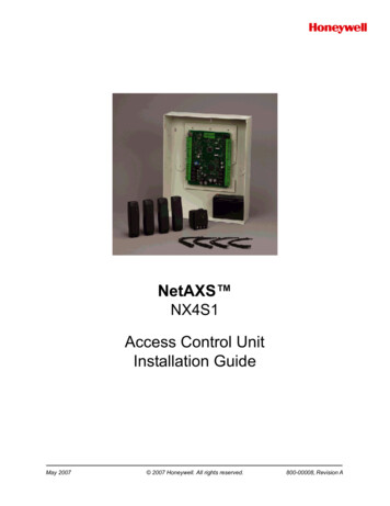
NetAXS-123Access Control UnitInstallation GuideMay 2010 2010 Honeywell. All rights reserved.800-05779, Revision A
Copyright 2010 Honeywell. All rights reserved.All product and brand names are the service marks, trademarks, registered trademarks,or registered service marks of their respective owners. Printed in the United States ofAmerica. Honeywell reserves the right to change any information in this document atany time without prior notice.Ordering InformationPlease contact your local Honeywell representative or visit us on the web atwww.honeywellaccess.com for information about ordering.FeedbackHoneywell appreciates your comments about this manual. Please visit us on the web atwww.honeywellaccess.com to post your comments.
CONTENTSInstalling the NetAXS-123 Panels1.0 Introduction . 21.1 Access Control Overview . 21.2 NetAXS-123 Overview. 22.0 Panel Components and Descriptions. 32.1 Supervised Input Wiring . 52.2 NetAXS-123 Access Control Unit. 7NetAXS-123 Add-On Board . 7Supported Readers . 8Real-Time Clock Protection . 92.3 Power Supply . 92.4 Battery. 102.5 Suppressors . 103.0 Installation. 113.1 Installing the Compact Enclosure Panel . 11Installing on a Wall . 11Installing over a Gang Box . 15Installing on a Flat Surface . 163.2 Installing the Standard Enclosure Panel . 173.3 Installing the Add-On Board. 263.4 Wiring the Readers . 293.5 Wiring Door Strikes. 333.6 Setting DIP Switches and Jumpers . 35Controller Board DIP Switch and Jumper Settings . 35Add-On Board DIP Switch and Jumper Settings . 403.7 Communications . 42USB Communications . 42RS-485 Communications . 44Ethernet TCP/IP Communications . 474.0 System Configuration . 484.1 Ethernet Connection . 484.2 USB Connection . 49NetAXS-123 Access Control Unit Installation Guide, Document 800-05779, Revision Aiii
4.3 RS-485 Connection via PCI-3 . 504.4 RS-485 Connection via NetAXS-123. 514.5 RS-485 Connections with Multidrop Panels at Both Ends of the Cable . 524.6 M-56K Dial-up Modem, RS-485 Connection via Hub (PCI-3) . 544.7 Fiber Converter to RS-485 Connection via PCI-3. 554.8 Fiber Converter to RS-485 Connection via NetAXS-123 . 564.9 N-485-PCI-3/NetAXS-123 Access Controller Panel Connection Detail . 574.10 NetAXS-123/NetAXS-123 Access Controller Panel Connection Detail . 584.11 Mixed Loops . 595.0 Hardware Specifications . 605.1 Relay Contacts . 605.2 Reader Interface . 605.3 Maximum Output Loading . 605.4 PoE Power Limitations . 605.5 Mechanical. 615.6 Environment. 625.7 Cable . 626.0 Basic Standalone Operation . 636.1 Card Read / Door Lock Operation. 636.2 Door Egress / Door Lock / Door Status Operation . 637.0 Maintenance . 648.0 Troubleshooting . 659.0 Technical Support . 669.1 Normal Support Hours. 669.2 Web . 66ivwww.honeywell.com
LIST OF FIGURESFigure 1: NetAXS-123 Compact Enclosure Wiring and Components . 3Figure 2: NetAXS-123 Standard Enclosure Panel Wiring and Components . 4Figure 3: NetAXS-123 Add-On Board Wiring and Components . 5Figure 4: Typical Supervised Input Wiring Diagram . 6Figure 5: Wiring Readers to the Controller Board . 29Figure 6: Controller Board DIP Switch and Jumper Location . 35Figure 7: NetAXS-123 Controller Board Jumpers . 39Figure 8: Add-On Board DIP Switch and Jumper Location . 40Figure 9: RS-485 Configuration via N-485-PCI-3 . 45Figure 10: RS-485 Configuration via NetAXS-123 Gateway . 46Figure 11: Ethernet TCP/IP Configuration . 47Figure 12: Ethernet Connection . 48Figure 13: NetAXS-123 USB Connection . 49Figure 14: RS-485 Connection via PCI-3 . 50Figure 15: RS-485 Connection via NetAXS-123 . 51Figure 16: RS-485 Connection via NetAXS-123 with Multidrop Panels at Both Ends . 52Figure 17: RS-485 Connection via PCI-3 with Multidrop Panels at Both Ends . 53Figure 18: M-56K Dial-up Modem, RS-485 Connection via Hub . 54Figure 19: Fiber Converter to RS-485 Connection via PCI-3 . 55Figure 20: Fiber Converter to RS-485 Connection via NetAXS-123 . 56Figure 21: N-485-PCI-3/NetAXS-123 Access Controller Panel Connection Detail . 57Figure 22: NetAXS-123/NetAXS-123 Access Controller Panel Connection Detail . 58NetAXS-123 Access Control Unit Installation Guide, Document 800-05779, Revision Av
viwww.honeywell.com
LIST OF TABLESTable 1: Supervised Input Terminal Blocks . 5Table 2: Supervised Tamper Terminal Blocks . 6Table 3: NetAXS-123 Input/Output Options . 7Table 4: Readers Supported by NetAXS-123 . 8Table 5: Factory Default Configuration Settings for Door 1 . 30Table 6: Factory Default Configuration Settings for Door 2 . 31Table 7: Factory Default Configuration Settings for Door 3 . 32Table 8: NetAXS-123 SW1 DIP Switch Settings . 36Table 9: NetAXS-123 SW2 DIP Switch Settings . 38Table 10: Reader Wiring . 62Table 11 Troubleshooting Problems and Solutions . 65NetAXS-123 Access Control Unit Installation Guide, Document 800-05779, Revision Avii
viiiwww.honeywell.com
Installing the NetAXS-123 PanelsIn this chapter .Introduction2Panel Components and Descriptions3Installation11System Configuration48Hardware nical Support66NetAXS-123 Access Control Unit Installation Guide, Document 800-05779, Revision A1
Installing the NetAXS-123 PanelsIntroduction1.0 IntroductionThis document describes how to install the NetAXS-123 Standard Enclosure access control unit andthe NetAXS-123 Compact Enclosure access control unit.1.1 Access Control OverviewAn access control system protects and preserves an enterprise’s resources by providing authentication,authorization, and administration services. Authentication is a process that verifies a user’s identity. Ifthe user is verified, the system then either grants or denies access to specific areas and resources.Administration includes the creation and modification of user accounts and access privileges.An access control system consists of hardware and software, usually configured in a networkenvironment over a standard network protocol. Access control units, readers, door strikes, and videoand other devices, for example, are configured to control and monitor the access to a company site.1.2 NetAXS-123 OverviewA NetAXS-123 access control is a full-featured one-door web-based access control system thatsupports up to three doors when supplemented with an add-on input/output board. The NetAXS-123panel includes a built-in web server, built-in Ethernet and USB support, and Power over Ethernet(PoE) capability. You can manage the access control system using either a web browser or WIN-PAK.For supported configurations, see “System Configuration“ on page 48 to view illustrations of thesupported NetAXS-123 system configurations.2www.honeywell.com
Installing the NetAXS-123 PanelsPanel Components and Descriptions2.0 Panel Components and DescriptionsNote: This device complies with part 15 of the FCC Rules. Operation is subject to the following twoconditions: (1) This device may not cause harmful interference, and (2) this device must accept anyinterference received, including interference that may cause undesired operation.The NetAXS-123 panel consists of a web-browser-enabled controller, a one- or two-door add-on boardthat supports additional inputs and outputs, a power-over-Ethernet (PoE) power supply (NetAXS-123Compact only), and a battery (NetAXS-123 Standard only).The following figures show the NetAXS-123 panel wiring and components.Figure 1:NetAXS-123 Compact Enclosure Wiring and ComponentsNetAXS-123 Access Control Unit Installation Guide, Document 800-05779, Revision A3
Installing the NetAXS-123 PanelsPanel Components and DescriptionsFigure 2:NetAXS-123 Standard Enclosure Panel Wiring and ComponentsMaintain at least a .25-inch distance between the non-power limited wiring (115 VAC/60 Hzinput wiring, power line filter wiring, and battery backup/charger wiring) and all other wiring, which ispower-limited Class 2 wiring.Note:4www.honeywell.com
Installing the NetAXS-123 PanelsPanel Components and DescriptionsFigure 3:NetAXS-123 Add-On Board Wiring and Components2.1 Supervised Input WiringThe supervised inputs are located on the following terminal blocks:Table 1: Supervised Input Terminal BlocksBoard ConfigurationTerminal Block1-Door (Controller Board)C-TB2C-TB101-Door (Add-On Board)IO-TB22-Door (Add-On Board)IO-TB2 (as 1-door Add-OnBoard)IO-TB6NetAXS-123 Access Control Unit Installation Guide, Document 800-05779, Revision A5
Installing the NetAXS-123 PanelsPanel Components and DescriptionsTampers can also be supervised. They are located on the following terminal blocks:Table 2: Supervised Tamper Terminal BlocksBoard ConfigurationTerminal Block1-Door (Controller Board)C-TB3/TMPR AC-TB4/TMPR B1-Door (Add-On Board)IO-TB3/TMPR AIO-TB4/TMPR B2-Door (Add-On Board)IO-TB3/TMPR AIO-TB4/TMPR BIO-TB7/TMPR AIO-TB8/TMPR BDoor Status (STS) and Request to Exit (REX) for all three doors may be configured for NormallyOpen or Normally Closed contacts as supervised or non-supervised. Inputs 5 (generic) and 6 (power)are on C-TB10. All seven inputs on the Controller Board and four inputs on the Add-On Board havedefault functions, but they can be configured for general purpose inputs.The following figure shows the typical wiring for a supervised input.Figure 4:Typical Supervised Input Wiring DiagramThe figure above shows standard 2,200 ohm resistors. The NetAXS-123 panel accepts 1,000, 2,200,4,700, or 10,000 ohm values. Note that both resistors must have the same value.In addition, the Reader tampers can be supervised and capable of being used as additional inputs if thedefault functionality is not needed.The wire used for the inputs should be shielded and cannot exceed 30 ohms over the entire length ofthe cable. Remember that the distance from the panel to the door must be doubled to determine thetotal resistance.Caution: Thecable shield should be grounded only at the panel earth ground. Grounding at both endscan cause ground loops which can be disruptive.6www.honeywell.com
Installing the NetAXS-123 PanelsPanel Components and DescriptionsCaution: Thesystem has not been verified for compliance with UL1076 Burglar Alarm units andsystems.2.2 NetAXS-123 Access Control UnitThe NetAXS-123 panel is a one-door access control unit that you can supplement with an add-onboard that supports second and third doors. The following table shows the NetAXS-123 input/outputoptions:Table 3: NetAXS-123 Input/Output OptionsBoardReadersInputs/OutputsController1 door/2 readers1 lock output1 aux output1 status input1 Request to Exit2 reader tamper/AUXinputsAdd-On (1 Door)1 door/2 readers1 lock output1 aux output1 status input1 Request to Exit2 reader tamper/AUXinputsAdd-On (2 Door)2 doors/4 readers2 lock outputs2 aux outputs2 status inputs2 Request to Exits4 readers tamper/AUXinputsYou can use the NetAXS-123 panel as a standalone panel with independent card and transactionstorage or, with a host software upgrade, as a fully monitored online access control device.Panel inputs are capable of four state supervision: Normal, Alarm, Short and Cut. One input is used forrequest to exit on each door and one input is used for door status on each door. Supervised inputs forExternal Power Fail and Reader Tampers are supplied as well, and they can be used as additionalinputs when not required for their default purpose.2.2.1 NetAXS-123 Add-On BoardThe NetAXS-123 Add-On Board enables you to expand from one door to either two or three doors.The board easily connects to the NetAXS-123 controller board (see the NetAXS-123 Add-On BoardInstallation Guide (800-05787).NetAXS-123 Access Control Unit Installation Guide, Document 800-05779, Revision A7
Installing the NetAXS-123 PanelsPanel Components and Descriptions2.2.2 Supported ReadersSupported readers include the following:Table 4: Readers Supported by NetAXS-123SeriesReader ModelHoneywell NEProxPoint Plus6005BMiniProxHU/5365EGP00Thinline 55AGN00ProxPro IIHU/5455BGN00ProxPro ss8www.honeywell.com
Installing the NetAXS-123 PanelsPanel Components and DescriptionsSeriesReader ModelHoneywell 35HONAOT36OT36HONAOT70OT70HONAOT75OT75HONADR 4200K92042000000DR 422092042200000NexWatchNote:For NetAXS-123 reader specifications, see Hardware Specifications, page 60.2.2.3 Real-Time Clock ProtectionThe panel RTC is backed up using a super capacitor. The super capacitor will power the real-timeclock for 24 hours in the absence of primary power or backup battery.2.3 Power SupplyThe NetAXS-123 Compact Enclosure is powered by Power Over Ethernet (PoE) injector. This PoEinjector can supply a total system current of 800mA to 900mA @ 12VDC. However the NetAXS-123controller board consumes 400mA of current, and it therefore leaves 450mA of total current for the12VDC external power. See Hardware Specifications, page 60, for further details on current limitsusing PoE.The Standard Enclosure uses a 12VDC 4A power supply with an international input of 100VAC to240VAC. The supply also charges and monitors the condition of the battery. Wire the unswitchedelectrical power to the supply per the National Electrical Code as well as any local electrical codes,including the safety ground wire.An input power indicator is supplied, and it is illuminated when input voltage is present. If theindicator is off, the input voltage is off, or too low to operate the system.Caution: Disconnectthe battery and AC power before servicing the fuse. For continued protectionagainst the risk of electric shock and fire hazard, replace the input fuse with a GMA type fuse with therating of 1A, 250V. The fuse is located in the lower-left corner in the cabinet, as shown below.NetAXS-123 Access Control Unit Installation Guide, Document 800-05779, Revision A9
Installing the NetAXS-123 PanelsPanel Components and Descriptions2.4 BatteryFor the NetAXS-123 Standard Enclosure panel, one CASIL CA1270, 12 VDC, 7A-hour sealedlead-acid battery (Honeywell order number 3-000066). The battery provides standby backup power,depending upon system configuration and activity. When AC is lost, the power supply automaticallyswitches to the backup battery for continuous 12VDC power. Replace the battery every 2 to 2.5 years,or more often if the system has a high rate of backup use.2.5 SuppressorsTwo suppressors (HAS number S-4) are required for each door lock. One suppressor is installed on thepanel control board, and the second must be installed at the door lock.10www.honeywell.com
Installing the NetAXS-123 PanelsInstallation3.0 Installation3.1 Installing the Compact Enclosure PanelPerform the following steps to install the NetAXS-123 Compact panel:Warning: Use a static strap whenever touching the panel to ensure protection from ElectrostaticDischarge (ESD).3.1.1 Installing on a Wall1. Review the panel layout, cable runs, and power needs.2. Mount the enclosure’s back at the proper location on the wall:a. Drill the screw holes in the wall, using the panel’s back as a template, and then pull thepower and all I/O wires to the enclosure and through the knockout holes, and properlymark each wire for its use.b. Screw the back of the panel to the wall, using either drywall screws or threaded wallanchors.NetAXS-123 Access Control Unit Installation Guide, Document 800-05779, Revision A11
Installing the NetAXS-123 PanelsInstallation3. Mount the board onto the back of the panel.4. Choose the tamper type (standard or off-the-wall tamper) and wire the tamper. Wiring a standard tamper:12www.honeywell.com
Installing the NetAXS-123 PanelsInstallation Wiring an off-the-wall tamper:5. Set the tamper, using pliers at the four locations indicated below.Warning: Donot apply power at this time.NetAXS-123 Access Control Unit Installation Guide, Document 800-05779, Revision A13
Installing the NetAXS-123 PanelsInstallation6. Connect the Ethernet cable and the Tamper wire, as shown below.7. Set DIP switch settings for the panel address, communication termination and biasing. See DIPSwitch Settings, page 36.8. Check all wiring at this time.Caution: Improper wiring can cause damage to the NetAXS-123 at power up and result in a lossof warranty.9. Apply power to the panel.10.Check for the Run LED for a successful power-up. If the LED is blinking green, the panel ispowered up successfully.11.Close the cover.14www.honeywell.com
Installing the NetAXS-123 PanelsInstallation3.1.2 Installing over a Gang Box1. Review the panel layout, cable runs, and power needs.2. Mount the back of the panel on the gang box.3. Pull the wires from the gang box through the knockout holes in the base of the enclosure.4. Perform steps 3 through 10 in the preceding section ( Installing on a Wall, page 11) to completethe installation of the panel over a gang box.NetAXS-123 Access Control Unit Installation Guide, Document 800-05779, Revision A15
Installing the NetAXS-123 PanelsInstallation3.1.3 Installing on a Flat Surface1. Review the panel layout, cable runs, and power needs.2. Mount the back of the enclosure on the surface, either with drywall screes or threaded wallanchors.3. Break off the appropriate plastic wiring tabs, using pliers.4. Perform steps 3 through 10 in Installing on a Wall, page 11 to complete the installation of thepanel over a horizontal surface.16www.honeywell.com
Installing the NetAXS-123 PanelsInstallation3.2 Installing the Standard Enclosure PanelPerform the following steps to install the NetAXS-123 Standard Enclosure panel:Warning: Use a static strap whenever touching the panel to ensure protection from ElectrostaticDischarge (ESD).1. (Optional) Remove the green ground wire and the door.2. Partially install the four power supply screws.NetAXS-123 Access Control Unit Installation Guide, Document 800-05779, Revision A17
Installing the NetAXS-123 PanelsInstallation3. Install the power supply.a. Fit the power supply screws through the key holes in the left side of the cabinet, and seatthe power supply by pulling down.b. From the outside of the cabinet, tighten the screws to lock the power supply in place.18www.honeywell.com
Installing the NetAXS-123 PanelsInstallationc. Inside the cabinet, screw in the two self-tapping screws (supplied in the product box) atthe top and bottom of the power supply.Warning: Thesescrews must be installed to ground the power supply to the enclosure.NetAXS-123 Access Control Unit Installation Guide, Document 800-05779, Revision A19
Installing the NetAXS-123 PanelsInstallationd. Plug the connector that is attached to the blue and brown wires into the power supply.20www.honeywell.com
Installing the NetAXS-123 PanelsInstallation4. Select one of the following three possible entry points for the power cable:Warning: Do not apply power at this time. Be sure the power cable is disconnected from theexternal power source before following this step. Through the bottom conduitknockout, which directly connectsAC power to the terminal block. Through the side conduit knockout,which also directly connects ACpower to the terminal block. Through the optional AC inputreceptacle. Note: the brown and bluewires must be twisted together fromthe point of entry at the AC inputreceptacle to the Terminal Block.NetAXS-123 Access Control Unit Installation Guide, Document 800-05779, Revision A21
Installing the NetAXS-123 PanelsInstallation5. Use a pencil to mark the location of the holes on the wall.6. Screw the NetAXS-123 Controller Board with the four captive screws22www.honeywell.com
Installing the NetAXS-123 PanelsInstallation7. Hold the Add-On Board over the Controller Board and seat the board-to-board connector intothe Controller Board. Secure the Add-On Board onto the Controller Board with the four captivefinger screws. For more explanation of the Add-On Board installation, see the next section,Installing the Add-On Board.NetAXS-123 Access Control Unit Installation Guide, Document 800-05779, Revision A23
Installing the NetAXS-123 PanelsInstallation8. Connect the wiring harness, as shown.Warning: DONOT CONNECT the AC power or the battery wires yet!9. Power up the NetAXS-123 Controller Board and configure the system. Refer to theNetAXS-123 Startup Guide (800-05780) for instructions.24www.honeywell.com
Installing the NetAXS-123 PanelsInstallation10.Connect the battery.11.Attach the door to the cabinet.12.Re-connect the green ground wire to the cabinet door.NetAXS-123 Access Control Unit Installation Guide, Document 800-05779, Revision A25
Installing the NetAXS-123 PanelsInstallation3.3 Installing the Add-On BoardWarning: Toprevent damage to the NXC1 Controller Board, remove power from theNetAXS-123 panel before installing or removing a NetAXS-123 Add-On Board.1. On the NetAXS-123 Controller Board, locate the four posts called out in the image shownbelow:NetAXS-123 Controller Board26www.honeywell.com
Installing the NetAXS-123 PanelsInstallation2. Pick up the Add-On Board and notice the four posts on the bottom.3. Seat the Add-On Board posts into the four posts on the NetAXS-123 Controller Board, aligningthe terminal-block edge of the Add-On Board with the terminal-block edge of the ControllerBoard.4. With your fingers, tighten the posts’screws.NetAXS-123 Access Control Unit Installation Guide, Document 800-05779, Revision A27
Installing the NetAXS-123 PanelsInstallation5. Set the relay jumpers.a. Use the following figure to locate the jumpers.b. See Add-On Board DIP Switch and Jumper Settings, page 40, to set the power source(12VDC power or external power) and the relay contact position (Normally Open orNormally Closed).6. Wire the door strikes. See Wiring Door Strikes, page 33, for instructions.28www.honeywell.com
Installing the NetAXS-123 PanelsInstallation3.4 Wiring the ReadersEach reader port supports one or two readers (entry and exit readers) with Wiegand output format. Themaximum power draw is 500 mA for readers and AUX Power combined.To fully utilize each reader port, a shielded 7-conductor cable (18-22 AWG) is required. If you don’tneed the HOLD LINE feature, you can use the standard 6-conductor cable (HAS part numberNC186-BL).Note:If you are using additional HOLD lines for readers, you will need an 8-conductor cable.The cable shield should be grounded at the panel only. Grounding at both ends can cause ground loopswhich can be disruptive. The maximum recommended length of wiring is 500 feet per reader.Figure 5 shows a one-door panel, with the readers wired to terminal blocks C-TB3 and C-TB4 on theController Board, and to terminal blocks IO-TB3, IO-TB4, IO-TB7, and IO-TB8 on the Add
2 www.honeywell.com Installing the NetAXS-123 Panels Introduction 1.0 Introduction This document describes how to install the NetAXS-123 Standard Enclosure access control unit and the NetAXS-123 Compact Enclosure access control unit. 1.1 Access Control Overview


![[1]Oracle Enterprise Manager Cloud Control Basic Installation Guide .](/img/34/e22624.jpg)