Transcription
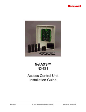
NetAXS NX4S1Access Control UnitInstallation GuideMay 2007 2007 Honeywell. All rights reserved.800-00008, Revision A
Copyright 2007 Honeywell. All rights reserved.All product and brand names are the service marks, trademarks, registered trademarks,or registered service marks of their respective owners. Printed in the United States ofAmerica. Honeywell reserves the right to change any information in this document atany time without prior notice.Ordering InformationPlease contact your local Honeywell representative or visit us on the web atwww.honeywellaccess.com for information about ordering.FeedbackHoneywell appreciates your comments about this manual. Please visit us on the web atwww.honeywellaccess.com to post your comments.
CONTENTSNetAXS NX4S1 Installation1.0 Notices .1.1 Warnings and Cautions .1.2 Product Liability, Mutual Indemnification .1.3 Limited Warranty.1.4 Federal Communications Commission.1.5 Industry Canada .1.6 Underwriters Laboratories Incorporated.11223342.0 Introduction . 52.1 Access Control Overview . 52.2 NetAXS Access Overview. 53.0 Panel Components and Descriptions.3.1 NetAXS Access Control Unit .Real-Time Clock Protection .Memory Protection .Reader and AUX Power .3.2 Power Supply .3.3 Battery.3.4 Enclosure .3.5 Suppressors .6777788884.0 Installation. 94.1 Cabinet Mounting . 104.2 Reader Wiring. 144.3 Supervised Input Wiring . 144.4 NX4S1 Control Output Wiring. 164.5 Communications . 16RS-232 Communications . 16RS-485 Communications . 18Ethernet TCP/IP Communications . 194.6 DIP Switch Settings . 214.7 Jumper Settings. 234.8 Downstream I/O. 23NetAXS Access Control Unit NX4S1 Installation Guide, Document 800-00008, Revision Aiii
5.0 System Configuration .5.1 RS-485 Connection via PCI-2 .5.2 RS-485 Connection via NetAXS .5.3 RS-485 Connections with Multidrop Panels at Both Ends of the Cable .5.4 RS-232 Connection.5.5 Ethernet Connection .5.6 LANSRLU1 Connection.5.7 RS-485 Short Haul Modem Connection via PCI-2 .5.8 RS-485 Short Haul Modem Connection via NetAXS .5.9 RS-232 Short Haul Modem Connection .5.10 M-56K Dial-up Modem, RS-485 Connection via Hub.5.11 M-56K Dial-up Modem, RS-485 Connection via NetAXS .5.12 Fiber Converter to RS-485 Connection via PCI-2.5.13 Fiber Converter to RS-485 Connection via NetAXS .5.14 N-485-PCI-2/NetAXS Access Controller Panel Connection Detail.5.15 NetAXS /NetAXS Access Controller Panel Connection Detail .262627283031323334353637383940416.0 NetAXS Startup . 426.1 LED Operation. 427.0 Hardware Specifications .7.1 Relay Contacts .7.2 Reader Interface .7.3 NX4S1 Wire Requirements .7.4 Maximum Output Loading .7.5 Common Connections.7.6 Mechanical.7.7 Environment.7.8 Communications and Wiring .7.9 Reader Wiring.7.10 NX4S1 Wiring Diagram .44444444444545454646478.0 Maintenance . 489.0 Troubleshooting . 4810.0 Technical Support . 4910.1 Normal Support Hours. 4910.2 Web . 49ivwww.honeywell.com
NetAXS Standalone OperationA.1 Basic Standalone Operations. 51A.1.1 Card Read / Door Lock Operation . 51A.1.2 Door Egress / Door Lock / Door Status Operation . 51A.2 Standalone Settings.A.2.1 NetAXS Panel Hardware Settings .A.2.2 Communication Settings.A.2.3 Emulation Settings .A.2.4 Verifying Communications.5252525252A.3 Standalone Commands .A.3.1 T (Time) Command .A.3.2 D (Date) Command.A.3.3 L (Time Zone) Command .A.3.4 C (Card Add) Command .A.3.5 C (Card Delete) Command .A.3.6 W (Input) Command .A.3.7 P (Interlock) Command.A.3.8 Flow Control Disable/Enable.535354555656575758A.4 NetAXS Panel Defaults .A.4.1 Reader Ports .A.4.2 Reader LED Outputs .A.4.3 Reader Tamper Inputs.A.4.4 Door Egress Inputs.A.4.5 Door Status Inputs.A.4.6 ACFAIL and Panel Tamper Inputs .A.4.7 Additional Generic Outputs .5959596060616162NetAXS Access Control Unit NX4S1 Installation Guide, Document 800-00008, Revision Av
viwww.honeywell.com
LIST OF FIGURESFigure 1: NX4S1 Panel Components . 6Figure 2: NetAXS NX4S1 Panel Cabinet, Front View . 10Figure 3: NetAXS NX4S1 Panel Cabinet, Top View . 11Figure 4: NetAXS NX4S1 Panel Cabinet, Bottom View . 11Figure 5: NetAXS Panel Cabinet, Left View . 12Figure 6: NetAXS NX4S1Panel Cabinet, Right View . 13Figure 7: Typical Supervised Input Wiring Diagram . 15Figure 8: RJ-45 Serial Port . 17Figure 9: RS-232 Configuration . 17Figure 10: RS-485 Configuration via N-485-PCI-2 or PCI-3 . 18Figure 11: RS-485 Configuration via NetAXS Gateway . 19Figure 12: Ethernet TCP/IP Configuration . 19Figure 13: Ethernet MAC Address Location . 20Figure 14: DIP Switch and Jumper Locations . 21Figure 15: Default Downstream I/O Configuration with Wiring . 25Figure 16: RS-485 Connection via PCI-2 . 26Figure 17: RS-485 Connection via NetAXS . 27Figure 18: RS-485 Connection via NetAXS with Multidrop Panels at Both Ends 28Figure 19: RS-485 Connection via PCI-2 with Multidrop Panels at Both Ends . 29Figure 20: RS-232 Connection . 30Figure 21: Ethernet Connection . 31Figure 22: LANSRLU1 Connection . 32Figure 23: RS-485 Short Haul Modem Connection via PCI-2 . 33Figure 24: RS-485 Short Haul Modem Connection via NetAXS . 34Figure 25: RS-232 Short Haul Modem Connection . 35Figure 26: M-56K Dial-up Modem, RS-485 Connection via Hub . 36Figure 27: M-56K Dial-up Modem, RS-485 Connection via NetAXS . 37Figure 28: Fiber Converter to RS-485 Connection via PCI-2 . 38Figure 29: Fiber Converter to RS-485 Connection via NetAXS . 39Figure 30: N-485-PCI-2/NetAXS Access Controller Panel Connection Detail . 40Figure 31: NetAXS /NetAXS Access Controller Panel Connection Detail . 41Figure 32: System, Relay and Power LEDs . 42Figure 33: NX4S1 Panel Wiring Diagram . 47NetAXS Access Control Unit NX4S1 Installation Guide, Document 800-00008, Revision Avii
viiiwww.honeywell.com
LIST OF TABLESTable 1Table 2Table 3Table 4Table 5Table 6Table 7Table 8Reader Wiring .Default Supervised Input Assignments .DIP Switch Settings .MIRO 32/0 DIP Switch and Jumper Settings .LED Status .Communications and Wiring .Reader Wiring .Troubleshooting Problems and Solutions .NetAXS Access Control Unit NX4S1 Installation Guide, Document 800-00008, Revision A1414222343464648ix
xwww.honeywell.com
NetAXS NX4S1 Installation1.0 Notices1.1 Warnings and CautionsWarning: Fire Safety and Liability Notice: Never connect card readers to any criticalentry, exit door, barrier, elevator or gate without providing an alternative exit inaccordance with all fire and life safety codes pertinent to the installation. These fireand safety codes vary from city to city and you must get approval from local fireofficials whenever using an electronic product to control a door or other barrier. Use ofegress buttons, for example, may be illegal in some cities. In most applications, singleaction exit without prior knowledge of what to do is a life safety requirement. Alwaysmake certain that any required approvals are obtained in writing. Verbal approvals arenot valid.Warning: Honeywell AccessSystems (HAS) never recommends using WIN-PAK orrelated products for use as a primary warning or monitoring system. Primary warningor monitoring systems should always meet local fire and safety code requirements.The installer must also test the system on a regular basis by instructing the end user inappropriate daily testing procedures. Failure to test a system regularly could makeinstaller liable for damages to the end user if a problem occurs.Warning: Earthground all enclosures for proper installation.Warning: Use suppressors on all door locks. Use HAS (part number S-4) suppressorsfor installation. Honeywell recommends only DC locks.Warning: Personalinjury or death could occur, and the equipment could be damagedbeyond repair, if this precaution is not observed! Before installation, turn off the external circuit breaker which supplies powerto the system, including door locks. Before connecting the device to the power supply, verify that the outputvoltage is within specifications of the power supply. Do not apply power to the system until after the installation has beencompleted.Caution: Ifany damage to the shipment is noticed, a claim must be filed with thecommercial carrier responsible.Caution: Electro-staticdischarge (ESD) can damage CMOS integrated circuits andmodules. To prevent damage always follow these procedures:NetAXS Access Control Unit NX4S1 Installation Guide, Document 800-00008, Revision A1
NetAXS NX4S1 InstallationNotices Use static shield packaging and containers to transport all electroniccomponents, including completed reader assemblies. Handle all ESD sensitive components at an approved static controlledworkstation. These workstations consist of a desk mat, floor mat and an ESDwrist strap. Workstations are available from various vendors.1.2 Product Liability, Mutual IndemnificationIn the event that a Customer receives a claim that a Product or any component thereofhas caused personal injury or damage to property of others, the Customer shallimmediately notify Honeywell in writing of all such claims. Honeywell shall defendor settle such claims and shall indemnify and hold the Customer harmless for anycosts or damages including reasonable attorneys’ fees which the Customer may berequired to pay as a result of the defective Product or the negligence of Honeywell, itsagents or its employees.The Customer shall hold harmless and indemnify Honeywell from and against allclaims, d
NetAXS Access Control Unit NX4S1 Installation Guide, Document 800-00008, Revision A 1 NetAXS NX4S1 Installation 1.0 Notices 1.1 Warnings and Cautions Warning: Fire Safety and Liability Notice: Never connect card readers to any critical entry, exit door, barrier,