Transcription
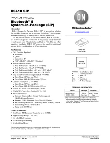
RSL10 Asset TagUser ManualUM70049/DThe RSL10 Asset Tag is an innovative development platformdesigned for a variety of industry 4.0 asset tracking and monitoringapplications. With environmental sensors, a 3 axis accelerometer andsupport for Bluetooth Low Energy connectivity and QuuppaIntelligent Locating Systemt Real Time Localization Services(RTLS), the tag can be used to provide valuable data and insights intoan asset’s state of being and location. The RSL10 Asset Tag offers anindustry leading extended battery life of five years, a significantimprovement compared to similar devices. This is made possible byt h e u l t r a l o w p o w e r c o n s u m p t i o n o f t h e R S L 1 0 r a d i oSystem on Chip (SoC), advanced gate switching (FPF1005), lowpower environmental sensors, and optimized firmware.This user manual provides an overview of the RSL10 Asset Tag(RSL10 ASSET TAG) hardware and software supporting software,and instructions for use.www.onsemi.comUSER MANUALKey Features Multi Protocol Wireless Connectivity Bluetooth LE Periodic AdvertisingTriggered Mode (Acceleration Threshold) Firmware Over the Air (FOTA) UpdatesReal Time Locating Services (RTLS) provided by theQuuppa Intelligent Locating SystemtUnprecedented Low Power Consumption for 5 YearBattery LifeEnvironmental Sensing Technology (Temperature,Pressure) and a 3-axis AccelerometerAdvanced Sensor Management Ultra Low Leakage Gate Switches Ultra Low Power 17 mJ Active Mode 150 nJ per second in StandbySmall Form Factor (27 mm Diameter)Supported by the RSL10 Sensor Beacon Mobile App(GooglePlayt)Easy Debugging/Programming Interface Figure 1. RSL10 Asset TagTo get started with the platform, insert the battery into thebattery holder, as shown in Figure 2 below.Unboxing the RSL10 Asset TagThe RSL10 Asset Tag board is shipped with pre flashedfirmware and a CR2016 3 V battery, as shown in Figure 1.Figure 2. Inserting the CR2016 Battery into theRSL10 Asset Tag Semiconductor Components Industries, LLC, 2021July, 2021 Rev. 01Publication Order Number:UM70049/D
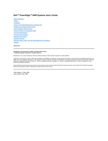
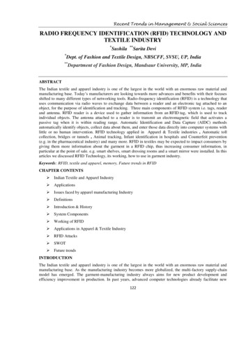
UM70049/DHARDWARE DESCRIPTIONThe RSL10 Asset Tag includes many different elementsincluding environmental sensors and the RSL10 SoC, whichis central to the platform. The Bluetooth 5 certified RSL10is embedded alongside a PCB antenna and matching circuit,and is used to capture and send sensor data and other wirelessfunctions including non connected Bluetooth LEadvertising and Firmware Over the Air (FOTA) updates.The tag also features a 10 pin header for debugging that canbe cut/removed depending on the application’s housingneeds.Figure 3. High Level System Block DiagramSensors and Gating Switchesaverage when in Power Down Mode and unprecedentedpower consumption in Default, Triggered and StorageModes.If you’re designing battery operated devices, powerconsumption must be minimized. I2C devices generallyconsume more power than SPI and, if power usage is aconcern, an SPI interface should be used for your design.The RSL10 Asset Tag uses an SPI bus that significantlyreduces overall consumption while in operation andgenerally features higher throughput bandwidth.Alongside the RSL10, the platform features two sensorswith unique, low power consumption profiles:BMP390L – low power environmental pressure sensorwith embedded temperature sensorMC3635 – low power accelerometer for motion sensingIn order to decrease the power consumption further, eachsensor features a unique supply gating thanks to theFPF1005 MOSFET load switch with an average currentconsumption of 1nA at 25 C. The BMP390L and MC3635provide a two pin power supply scheme: VDD core andVDDIO. The VDDIO pin is always connected to the batteryvoltage and supplies the digital domain of the sensor. TheVDD pin is the sensors’ core voltage gated over theFPF1005. Thanks to this arrangement as well as the RSL10Deep Sleep modes, the entire platform returns 25 nA onLow Cost Dome SwitchIn order to reduce the overall cost of the solution andenable easier embedding into the device enclosure, amulti purpose dome switch has been selected for the design.It sits underneath the battery, as depicted in Figure 4.Figure 4. RSL10 Asset tag Dome Switchwww.onsemi.com2
UM70049/DWhen the battery is inserted, depending on their productdevelopment requirements , designers can decide to enabletoggling of the switch by holding the board with two fingersand pressing the battery holder. You should hear a clickingsound to confirm that the dome switch has been pressed.Various modes of operation are set this way, as described infurther chapters.NOTE: You do not have to toggle the switch upon firstinsertion.Figure 5. Toggling the Dome SwitchPCB Antenna and Matching CircuitThe RSL10 Asset Tag features a low cost PCB antennaand matching circuit (Fig.6) that has been thoroughlyoptimized and measured for Bluetooth LE 5.0 emissions.Figure 6. RSL10 Asset Tag Impedance Measure Matchwww.onsemi.com3
UM70049/DExternal PinsRSL10 ASSET TAG Software Development KitExternal pads are available on the RSL10 Asset Tag thatcan be used: Firmware debugging in Sleep Modes RF measurements (Direct Test Mode) External trigger pins External sensorsThe RSL10 Asset Tag is supported by a fully featured andflexible Software Development Kit (SDK) that provides anexcellent out of the box experience. The SDK is providedwith a CMSIS Pack, easy installation and menu basedconfigurations for starter programmers.10 PIN SEGGER DEBUG INTERFACEThe RSL10 Asset Tag features a dedicated debuginterface: 6 pin needle adapter (mainly suited for mass productionsand flashing the production firmware) 10 pin header (appendix for comfortable debugging andfirmware development)Figure 7 depicts the location of the external GIO pads.Due to flexible RSL10 crossbar structure, GIOs can beconfigured for various purposes using the RSL10 SoftwareDevelopment Kit (SDK).A standard J Link debugger is supported for this purpose.For successful debugging, follow this procedure:1. Insert battery into RSL10 Asset Tag board (batterycreates reference voltage for debugger’s digitalsignals)2. Connect external J link debugger (10 pin / 6 pin)3. Install the RSL10 IDE and CMSIS packs,asdescribed in the following sections4. For debugging principles with ON SemiconductorIDE, please refer to Getting Started Guide eless rf transceivers/rsl10Figure 7. RSL10 Asset Tag External GIO PadsFigure 8.www.onsemi.com4
UM70049/DFigure 9. SECO RSL10 TAG GEVB Evaluation Board and Connection to J LINK DebuggerSoftware Prerequisites Importing the CMSIS PacksAfter the CMSIS packs are successfully imported, theycan be viewed in the CMSIS pack manager perspective asshown below (Fig. 10). The RSL10 Asset Tag CMSIS Packsupports two sample codes: Atag bootloader application Atag demo ble tag applicationJava (64 bit version)J Link software (version 6.32i or higher)ARM CMSIS 5ON Semiconductor IDE InstallerRSL10 Software Package (Installation steps provided inthe RSL10 Getting Started Guide)RSL10 Asset Tag CMSIS Pack(ONSemiconductor.RSL10 ATAG BSP.1.0.0)Figure 10. Imported CMSIS PacksCopying Sample Code into the Project Space1. Right click on the Atag demo ble tag sampleapplication and select Copy.Figure 11. Copying Sample Code into the Project Workspacewww.onsemi.com5
UM70049/DOnce the sample code is copied, you will have access tothe complete source code and readme features detailing thesample application and description (Figure 12).Figure 12. Expanded Sample Code with Available Documentationwww.onsemi.com6
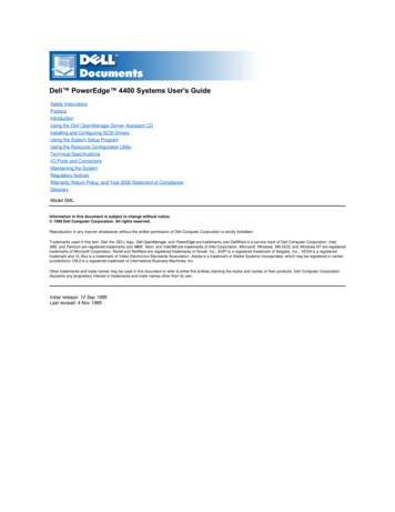
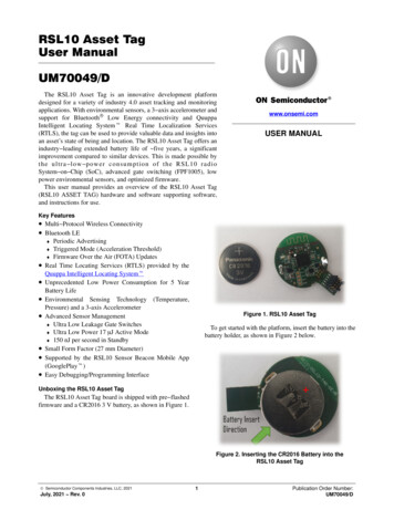
UM70049/D Storage ModeRSL10 ASSET TAG DEMO SAMPLE APPLICATION OverviewThe RSL10 Asset Tag demo application demonstrates theultra low power features of RSL10 Bluetooth 5 radioSystem on Chip (SoC) in an asset tracking use case. Theuse case has several modes of operation that switchautomatically based on external triggers including anaccelerometer sensor or push button.The application uses the following operation modes: Triggered Mode Used for tracking of moving objects. High advertising rate sufficient for walking speeds Advertising data contain pressure data to enhancetracking performance in multi story buildings Default Mode Used for tracking of stationary objects. Low advertising rate to report object presence Continuously detects motion events to switch intoTriggered Mode as needed Power save entered when object remained stationaryfor specified period of time No advertising Continuously detects motion events to switch intoTriggered Mode as needed Can be disabled in the project configuration ifcontinuous tracking is requiredFirmware Over the Air Mode Used to update device firmware. Entered by pressing the push button 3 times in quicksuccession.Power Down Mode Device is disabled and can be woken up only bypressing the push button. No advertising and no motion detection.The state diagram in Figure 13 shows the relationshipbetween all operation modes and default conditions fortransitioning between states. Detailed descriptions andconfigurations of each state are described in the ApplicationDescription section.Figure 13. Application State Diagramwww.onsemi.com7
UM70049/DBuild ConfigurationsBUILDING A PROJECTThis sample code contains two preconfigured buildconfigurations:1. Debug Project is built with O0 optimization forenhanced debugging experience.2. Release Project is built with Os optimization forreduced code size and speed optimizations that donot negatively impact code size.Firmware Over the Air (FOTA) DependenciesThis sample application generates FOTA capable imagesthat require additional external dependencies. Python v2.7 or later (* Ensure this is added to thesystem path) Package ecdsa version 0.13 or later Package pyserial version 3.2 or laterConfigurationRefer to RSL10 Firmware Over The Air User Guide withRSL10 Documentation Package for more details on FOTAimplementation.The application provides multiple RTE configuration filesthat allow developers to modify the application’s behaviour.The configuration files can be opened using the CMSISConfiguration Wizard Editor that is available as one of theeditors within the supported IDEs.Figure 14. Selecting CMSIS Configuration Wizard as Editor for File in ON Semiconductor IDE RTE/Board Support/m drv mc36xx config.hHere is a list of the RTE configuration headers includedwith this sample project: include/app config.h Contains configuration variablesrelated to operation states and application itself. RTE/Board Support/onsemi atag config.h Allowsyou to configure options exposed by the board supportcomponents. RTE/Board Support/atag assert config.c – Allows youto provide customized handler for failed assertions. Contains additional parameters of the low level driverlibrary used by the MC3635 accelerometer sensor.RTE/Device/RSL10/RTE Device.h Configuration filefor RSL10 peripherals. Used to configure the I2C and SPIinterfaces.www.onsemi.com8
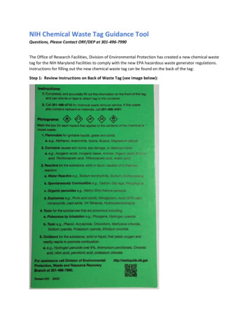
UM70049/DFlashing Proceduresby mkfotaimg.py python script when project is build. Thisbinary image merges the pre compiled fota.bin binarywith the application binary and adds signatures orchecksums of the binaries that are used to confirm imageintegrity during FOTA firmware updates FOTA Bluetooth LE stack binaryThis binary contains shared parts of the BluetoothLE stack and DFU application that are used duringfirmware update process. Application BinaryThis binary contains the application itself and it isdependent on the Bluetooth LEstack functions fromthe FOTA image.To enable FOTA functionality, the application is dividedinto multiple blocks that need to be loaded into device’sFlash memory. These components are shown in Figure 15and consist of: BootloaderBootloader is the permanent part of the application thatresides at the start of Flash memory and loads applicationimages if available. Pre compiled bootloader binaries forsupportedplatformsarelocatedinthe/Boards/ Board Name /Binaries/ folder of theCMSIS Pack. The bootloader project is also available asexample project atag bootloader FOTA Application ImageThe application image with .fota extension is generatedFigure 15. Layout of RSL10 Flash Memory with All Required Application ComponentsNote:Pre compiled FLASH images of the application withdefaultsettingsareavailableinthe/Boards/ Board Name /Binaries/ sub folder of theCMSIS Pack.The default CMSIS Pack root directory used byON SemiconductorIDEis(Fig. 16):C:\\Users\ username \ON Semiconductor\PACK\ONSemiconductor\RSL10 ATAG BSP\1.0.0\The same result can be achieved by any tool that can modifyand merge binary files and provides output into a .hex fileformat.Using srec cat to Merge ImagesThe srec cat.exe utility must be available on yourcomputer. This program can be downloaded from theproject’s SourceForge page:https://sourceforge.net/projects/srecord/1. Buildprojectandcopygeneratedatag demo ble tag.fotafilefromtheDebug/Release build folder into your preferredworking directory.2. Copy bootloader image file atag bootloader.hex foryour board from /Boards/ Board Name /Binaries/folder of the CMSIS Pack and place it inside yourworking directory.3. Open terminal in your working directory and run thesrec cat utility with following arguments:srec cat.exeatag bootloader.hex intelatag demo ble tag.fota binary offset 0x102000 o flash image.hex intelAfter this step a flash image.hex file will appear inthe working directory.4. Load the flash image.hex file into developmentboard using the RSL10 Standalone Flash LoaderUtility and J Link debug probe with appropriatedebug adapter.Figure 16. Un packed RSL10 Asset TagCMSIS PackGenerating the Initial Flash Image (Bootloader FOTA Application)The steps below describe how to generate and flash aninitial image onto an empty or erased development board.The provided instructions below are for the srec cat utility.www.onsemi.com9
UM70049/DFirmware Over the Air (FOTA) UpdatesEntering FOTA ModeThe Firmware over the Air (FOTA) allows firmwareupdates to be sent wirelessly. Two methods are available forperforming of FOTA updates on FOTA enabled devices: RSL10 FOTA Mobile Application (Android, iOS) FOTA.Console PC Tool with RSL10 USB DongleThe RSL10 Asset Tag board can be switched into FOTAMode by pressing the pushbutton three times in quicksuccession. After successful entering FOTA mode, thedevice will start advertising with the device name set to ONFOTA RSL10.Both methods are described in the RSL10 FirmwareOver The Air User’s Guide from RSL10 DocumentationPackage in section 4.4 and section 9.APPLICATION DESCRIPTIONOperation Modesthan compared to Default Mode to allow better tracking ofan object in motion. Typical examples for this mode includea person walking through a building or a cargo crate beingtransported through a facility or assembly line.Accelerometer sensor and motion detection is disabledwhile the device is in Triggered Mode. The sensor isautomatically re enabled a few seconds before transitionback to Default Mode to check for additional motion events.This section provides detailed description of availableoperation modes and their default configuration parameters.Triggered ModeThis mode is entered as a response to external triggers thatsignal that the device is in motion or in response to an outsideinteraction using the pushbutton. As such, the advertisinginterval and sample rate of pressure data are much smallerTable 1.FeatureValueDescriptionAdvertising Interval250 msHigh advertising rate to keep track of moving objects.No Motion Timeout20 sTime after which device returns to Default Mode if no motion events are detected.Accelerometer restart time15 sTime after which to re enable accelerometer and motion detection.Sensor sample rate2sSample rate for pressure, temperature and battery voltage data.Default Modeeither stop advertising entirely after a set period of time orremain active until next motion trigger is received.Motion detection can be disabled to require button pressbefore entering into Triggered Mode. Likewise, themeasurement of pressure, temperature and battery voltagecan be disabled too if the use case does not require thesefields.This mode is intended for tracking of objects that arestationary for longer periods of time. In this cas,e the deviceswitches to low advertising rate to report that the device isstill present in the area.Typical examples for when device is in this mode are aperson sitting at a desk or a cargo crate on a shelf. Dependingon whether or not Storage Mode is enabled, the device willTable 2.FeatureValueDescriptionAdvertising Interval10 sLow advertising rate to save power but still report object presence.No Motion Timeout2hTime after which device returns to Storage mode if no motion events were detected.60 sSample rate for pressure, temperature and battery voltage data.Sensor sample rateMotion TriggerEnabledAccelerometer is enabled at all times to allow switch to Triggered mode.Storage Modecompletely disabled if not desired for the use case.TheRSL10 is completely powered down (external wake upwith no RAM retention) when entering into this mode.When the pushbutton is pressed or a motion event occurs, thedevice executes Flash wake up that resets the device andenters into Triggered Mode.Storage Mode is entered after the device is in a longerperiod of inactivity with no motion. The device powersdown and only the accelerometer and motion trigger are leftactive to allow for transition back into Triggered Mode. Anexample of this mode includes a forklift being left overnightafter a work shift has ended. This operation mode can bewww.onsemi.com10
UM70049/DTable 3.FeatureValueDescriptionAdvertising IntervalN/ADevice is disabled.Sensor sample rateN/ASensors are disabled.Motion TriggerEnabledAccelerometer is enabled at all times to allow switch to Triggered mode.Power Down ModeFOTA ModeThis mode is identical to Storage Mode with these twoconditions: Can be entered only by holding the push button pressedfor more than 2 seconds. Accelerometer is always disabled while in Power DownMode. The pushbutton is the only way to wake up thedevice.When switched into this mode, the application control ispassed to the DFU application that handles firmware updateprocess. After firmware updates are complete, the device isreset.Power ConsumptionThe table below lists expected power consumption of theRSL10 Asset Tag while the board is in a given operationmode. Various combinations of sensor settings are listedbased on the available configuration options.Table 4.Adv.IntervalTXPowerTriggered Mode250 ms0 dBmTriggered ModeOperation @3VLifeExpectancy1,2LifeExpectancy1,2Off2s32.7 mA8.7 months0.7 years250 ms0 dBmOffOff29.4 mA9.6 months0.8 yearsDefault Mode10 s0 dBm6.5 Hz SNIFF60 s1.45 mA195 months16.3 yearsDefault Mode10 s0 dBmOff60 s1.10 mA257 months21.5 yearsDefault Mode10 s0 dBmOffOff982 nA288 months24.1 yearsStorage ModeN/A0 dBm6.5 Hz SNIFFOff342 nA829 months69 yearsPower Down ModeN/A0 dBmOffOff25 nAN/AN/A 1 Assumes 230 mAh CR2032 battery and 90% battery efficiency (207 mAh)2 Does not include startup and state transition events.Advertising Data PayloadThis example uses a custom 128 bit service data‘advertising structure to expose the following informationabout the tag: Firmware Version Device State Current Operation Mode Motion event counter Button press counter Ambient Temperature Atmospheric Pressure Battery VoltageFor documentation of the advertising structure refer to theCustom Advertising Data Types manual (UM700019) HTML documentation of the Utility.BLE Advertisingdata.ATAG AD Generator CMSIS Pack component.www.onsemi.com11
UM70049/DFigure 17. TAG Advertising Payload Structure Overview taken from HTML DocumentationRSL10 SENSOR BEACON MOBILE APPThe RSL10 Asset Tag supports data and statesvisualizations using the RSL10 Sensor Beacon app.Getting Started with the RSL10 Sensor Beacon App1. Ensure that geo location and Bluetooth settings areenabled in the phone2. Open the mobile app RSL10 Sensor Beacon3. The app’s discovery screen will show the State of theTag, RSSI, temperature and pressure readings. Themobile app filters the RSL10 Asset Tags and showsas many as possible if in closer proximity of themobile device (Figures 18, 19, 20, 21).Figure 20. Discovery Screen Triggered StateInvoked by MotionFigure 21. Discovery Screen Triggered StateInvoked by ButtonFigure 18. Mobile App Discovery Screen4. By tapping on the discovery screen, you will switchto the Advanced screen where you can exploredevice status and sensor readings, battery voltageand firmware revision (Fig. 22). You can also switchthe screen into a chart mode by swiping left close tothe ‘two dots’. The data charts will show and storesensor values and state over time.Figure 19. Discovery Screen Default Statewww.onsemi.com12
UM70049/DFigure 22. Switching from Advanced to Chart Mode5. In order to save the data into a .csv file within yourmobile phone, tap on the left arrow. Then, on theAdvanced Options screen, select the three dots to seethe Export Data button.Figure 23. Exporting Data into the .csv Filewww.onsemi.com13
UM70049/DBluetooth is a registered trademark of Bluetooth SIG.Google Play is a trademark of Google LLC.Quuppa Intelligent Locating System is a trademark of Quuppa company in the EU and/or elsewhere.ON Semiconductor andare trademarks of Semiconductor Components Industries, LLC dba ON Semiconductor or its subsidiaries in the United States and/or other countries.ON Semiconductor owns the rights to a number of patents, trademarks, copyrights, trade secrets, and other intellectual property. A listing of ON Semiconductor’s product/patentcoverage may be accessed at www.onsemi.com/site/pdf/Patent Marking.pdf. ON Semiconductor reserves the right to make changes without further notice to any products herein.ON Semiconductor makes no warranty, representation or guarantee regarding the suitability of its products for any particular purpose, nor does ON Semiconductor assume any liabilityarising out of the application or use of any product or circuit, and specifically disclaims any and all liability, including without limitation special, consequential or incidental damages.Buyer is responsible for its products and applications using ON Semiconductor products, including compliance with all laws, regulations and safety requirements or standards,regardless of any support or applications information provided by ON Semiconductor. “Typical” parameters which may be provided in ON Semiconductor data sheets and/orspecifications can and do vary in different applications and actual performance may vary over time. All operating parameters, including “Typicals” must be validated for each customerapplication by customer’s technical experts. ON Semiconductor does not convey any license under its patent rights nor the rights of others. ON Semiconductor products are notdesigned, intended, or authorized for use as a critical component in life support systems or any FDA Class 3 medical devices or medical devices with a same or similar classificationin a foreign jurisdiction or any devices intended for implantation in the human body. Should Buyer purchase or use ON Semiconductor products for any such unintended or unauthorizedapplication, Buyer shall indemnify and hold ON Semiconductor and its officers, employees, subsidiaries, affiliates, and distributors harmless against all claims, costs, damages, andexpenses, and reasonable attorney fees arising out of, directly or indirectly, any claim of personal injury or death associated with such unintended or unauthorized use, even if suchclaim alleges that ON Semiconductor was negligent regarding the design or manufacture of the part. ON Semiconductor is an Equal Opportunity/Affirmative Action Employer. Thisliterature is subject to all applicable copyright laws and is not for resale in any manner.PUBLICATION ORDERING INFORMATIONLITERATURE FULFILLMENT:Email Requests to: orderlit@onsemi.comON Semiconductor Website: www.onsemi.com TECHNICAL SUPPORTNorth American Technical Support:Voice Mail: 1 800 282 9855 Toll Free USA/CanadaPhone: 011 421 33 790 2910www.onsemi.com14Europe, Middle East and Africa Technical Support:Phone: 00421 33 790 2910For additional information, please contact your local Sales Representative
UM70049/D www.onsemi.com 5 Figure 9. SECO RSL10 TAG GEVB Evaluation Board and Connection to J LINK Debugger Software Prerequisites Java (64 bit version) J Link software (version 6.32i or higher) ARM CMSIS 5 ON Semiconductor IDE Installer RSL10 Software Package (Installation steps provided in the RSL10 Getting Started Guide)