Transcription
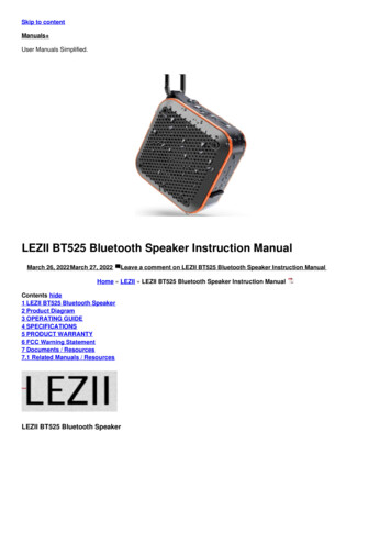
RSL10 SIPProduct PreviewBluetooth) 5System-in-Package (SiP)IntroductionRSL10 System In Package (RSL10 SIP) is a complete solutionthat provides the easiest way to integrate the industry’s lowest powerBluetooth low energy technology into a wireless application.The RSL10 SIP features an on board antenna, RSL10 radio SoC,and all necessary passive components in one package to help minimizeoverall system size. Already fully qualified to FCC, CE, and otherregulatory standards; RSL10 SIP removes the need for additionalantenna design considerations or RF certifications.www.onsemi.comSIP51 8x6CASE 127EYKey Features Fully Certified (Pending): Bluetooth 5QDID Declaration ID FCC*, CE, IC*, MIC, KC* (*Pending)Industry’s Lowest Power: Peak Rx Current 5.6 mA (1.25 V VBAT) Peak Rx Current 3.0 mA (3 V VBAT) Peak Tx Current (0 dBm) 8.9 mA (1.25 V VBAT) Peak Tx Current (0 dBm) 4.6 mA (3 V VBAT)Deep Sleep Current Consumption (1.25 V VBAT): Deep Sleep, IO Wake up: 50 nA Deep Sleep, 8 kB RAM Retention: 300 nACurrent Consumption (3 V VBAT): Deep Sleep, IO Wake up: 25 nA Deep Sleep, 8 kB RAM Retention: 100 nAEEMBC ULPMark Core Profile (3 V): 1090EEMBC ULPMark Core Profile (2.1 V): 1360Advanced Wireless: Supports Bluetooth Low Energy Technology and2.4 GHz Custom Protocols Supports FOTA (Firmware Over The Air) Updates Rx Sensitivity (Bluetooth Low Energy Mode, 1 Mbps): 93 dB Transmitting Power: 17 to 0 dBm Range up to 100 Meters XXXXXAWLYWW(SIP51)XXXXXXAWLYWWG or G Specific Device Code Assembly Location Wafer Lot Year Work Week Pb Free PackageORDERING INFORMATIONDevicePackageShipping†NCH RSL10 101S51 ACGSIP51(Pb Free)2500 / Tape &Reel†For information on tape and reel specifications,including part orientation and tape sizes, pleaserefer to our Tape and Reel Packaging SpecificationBrochure, BRD8011/D.Other Key Features Arm Cortex M3 Processor Clocked at up to 48 MHzSupply Voltage Range: 1.1 3.3 V384 kB of Flash Memory76 kB of Program Memory88 kB of Data MemoryThis document contains information on a product under development. ON Semiconductorreserves the right to change or discontinue this product without notice. Semiconductor Components Industries, LLC, 2018August, 2018 Rev. P21Publication Order Number:RSL10SIP/D
RSL10 SIPFEATURES Arm Cortex M3 Processor: A 32 bit core for Standby Mode: Can be used to reduce the averagereal time applications, specifically developed to enablehigh performance low cost platforms for a broad rangeof low power applications.LPDSP32: A 32 bit Dual Harvard DSP core thatefficiently supports intensive signal processingapplications. Various codecs are available to customersthrough libraries that are included in RSL10’sdevelopment tools.Radio Frequency Front End: Based on a 2.4 GHz RFtransceiver, the RFFE implements the physical layer ofthe Bluetooth low energy technology standard and otherproprietary or custom protocols.Protocol Baseband Hardware: Bluetooth 5 certifiedand includes support for a 2 Mbps RF link and customprotocol options. The RSL10 baseband stack issupplemented by support structures that enableimplementation of ON Semiconductor and customerdesigned custom protocols.Highly Integrated SoC: The dual core architecture iscomplemented by high efficiency power managementunits, oscillators, flash and RAM memories, a DMAcontroller, along with a full complement of peripheralsand interfaces.Deep Sleep Mode: RSL10 can be put into a DeepSleep Mode when no operations are required. VariousDeep Sleep Mode configurations are available,including: “IO wake up” configuration. The powerconsumption in deep sleep mode is 50 nA (1.25 VVBAT). Embedded 32 kHz oscillator running with interruptsfrom timer or external pin. The total current drain is90 nA (1.25 V VBAT). As above with 8 kB RAM data retention. The totalcurrent drain is 300 nA (1.25 V VBAT). With the exception of IO wake up onlyconfiguration, the on chip buck converter can alsobe enabled to reduce current consumption in DeepSleep Mode (at higher VBAT voltages). power consumption for off duty cycle operation,ranging typically from a few ms to a few hundreds ofms. The typical chip power consumption is 30 mA inStandby Mode.Multi Protocol Support: Using the flexibilityprovided by LPDSP32, the Arm Cortex M3 processor,and the RF front end; proprietary protocols and othercustom protocols are supported.Flexible Supply Voltage: RSL10 integrates high efficiency power regulators and has a VBAT range of1.1 to 3.3 V.Highly Configurable Interfaces: , UART, two SPIinterfaces, PCM interface, multiple GPIOs. It alsosupports a digital microphone interface (DMIC) and anoutput driver (OD).Flexible Clocking Scheme: RSL10 must be clockedfrom the XTAL/PLL of the radio front end at 48 MHzwhen transmitting or receiving RF traffic. When RSL10is not transmitting/receiving RF traffic, it can run offthe 48 MHz XTAL, the internal RC oscillators, the32 kHz oscillator, or an external clock. A lowfrequency RTC clock at 32 kHz can also be used inDeep Sleep Mode. It can be sourced from either theinternal XTAL, the RC oscillator, or a digital input pad.Diverse Memory Architecture: 76 kB of SRAMprogram memory and 88 kB of SRAM data memoryare available. A total of 384 kB of flash is available tostore the Bluetooth stack and other applications. TheArm Cortex M3 processor can execute from SRAMand/or flash.IP Protection Feature: Ensures that the customer’sflash contents cannot be copied by a third party. Itprevents any core or memory from being accessedexternally after the chip has booted.Ultra Low Power Consumption ApplicationExamples: Low Duty Cycle Advertising: IDD 1.1 mA foradvertising at all three channels at 5 second intervals@ VBAT 3 V, DCDC converter enabled.RoHS Compliant Devicewww.onsemi.com2
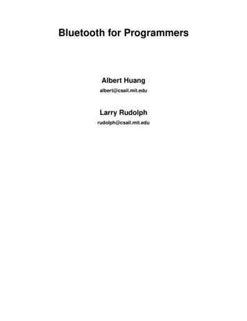
RSL10 SIPNoticeAll specifications for the RSL10 System in Package arebased on the RSL10 radio SoC. The RSL10 SIP data sheetonly contains key parameters. For a full list of RSL10parameters and specifications, refer to the RSL10 data sheet.inside the SiP. If an external antenna is used instead of theantenna internal to the SiP, this external antenna needs to beconnected to PIN E1.Additionally, an external PCB connection between theVDDO and VBAT pads is required. This connection ensuresthat the logic high level for the digital I/O (DIO) pads isequal to VBAT.Figures 1 and 2 show proposed layout patterns for theRSL10 SIP. The specific layout pattern used in theapplication may have to be adjusted to meet certain needs ofthe PCB manufacturer or assembly house. PCB design filesfor the RSL10 SIP are available at www.onsemi.com.Application Board ConnectionThe RSL10 SIP is designed to be reflowed onto low costprinted circuit boards. The RSL10 SIP connects to theapplication board via solder pads located on the bottom.To properly operate the RSL10 SIP an external PCBconnection between the RF and ANT pads is required. Thisconnection connects the RF pin on RSL10 to the antennaNotes:1. Align component edge to PCB edge if possible.2. Extend keepout area to PCB edge.3. Keepout area All layers.4. Keepout area Top layer only.5. Units mm.Figure 1. RSL10 SIP Keepout Area Requirementswww.onsemi.com3
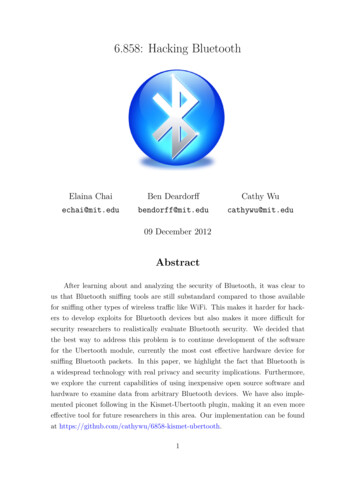
RSL10 SIPNotes:1. When incorporating internal antenna, join landing pads using 0.40 x 1.10 shape.2. Establish 50 (Ohm symbol) impedance to underlying reference plane.3. Maintain minimum 300 (uM symbol) distance from ground plane.4. Area for several vias.5. Refer to radiation efficiency data for applicable ground plane sizing,6. Units MM.Figure 2. Minimum Top Layer Ground Structurewww.onsemi.com4
RSL10 SIPRSL10 SiP SchematicThe schematic for the RSL10 SIP is shown in Figure 3.Figure 3. RSL10 SIP Schematicwww.onsemi.com5
RSL10 SIPPAD FUNCTION DESCRIPTIONFor detailed pad function information see the RSL10 data sheet.Table 1. PAD LISTPad IdentifierPad NameI/OA/DPullA1JTMSI/ODUA2DOI12I/ODU/DDigital input output 12A3JTCKI/ODUCM3 JTAG Test ClockA4DOI10I/ODU/DDigital input output 10A5DOI6I/ODU/DDigital input output 6A6DOI3I/OA/DU/DDigital input output 3 / ADC 3A7DOI2I/OA/DU/DDigital input output 2 / ADC 2A8DOI5I/ODU/DDigital input output 5B1DOI13I/ODU/DDigital input output/CM3 JTAG Test ResetB2DOI14I/ODU/DDigital input output/CM3 JTAG Test Data InB3DOI11I/ODU/DDigital input output 11B5DOI8I/ODU/DDigital input output 8B6DOI1I/OA/DU/DDigital input output 1 / ADC 1B7DOI7I/ODU/DDigital input output 7B8DOI4I/ODU/DDigital input output 4C1DOI15I/ODU/DDigital input output/CM3 JTAG Test Data OutC2DOI9I/ODU/DDigital input output 9C7DOI0I/OA/DU/DDigital input output 0 / ADC 0C8EXT tal O/I voltage supplyD8VBATIPBattery input voltageE1RFI/OARF signal og test 7RESIDF8WAKEUPIAWake up pin for power m6DescriptionCM3 JTAG Test Mode StateExternal clock inputReset pinRESERVED
RSL10 SIPTable 1. PAD LISTPad IdentifierPad dTable 2. ABSOLUTE MAXIMUM RATINGSSymbolParameterMinMaxUnit 3.63VVBATPower supply voltageVDDOI/O supply voltage 3.63VVSSRFRF front end ground 0.3 VVSSAAnalog ground 0.3 VVSSDDigital core and I/O ground 0.3 VVSSD 0.3VDDO 0.3VFunctional temperature range 4085 CStorage temperature range 4085 CVinT functionalT storageVoltage at any input pinCaution: Class 2 ESD Sensitivity, JESD22 A114 B (2000 V)The QFN package meets 450 V CDM levelStresses exceeding those listed in the Maximum Ratings table may damage the device. If any of these limits are exceeded, device functionalityshould not be assumed, damage may occur and reliability may be affected.www.onsemi.com7
RSL10 SIPTable 3. RECOMMENDED OPERATING CONDITIONSDescriptionSupply voltage operating rangeSymbolVBATConditionsInput supply voltage on VBAT pin (Note 1)MinTypMaxUnits1.181.253.3VFunctional operation above the stresses listed in the Recommended Operating Ranges is not implied. Extended exposure to stresses beyondthe Recommended Operating Ranges limits may affect device reliability.1. In order to be able to use a VBAT Min of 1.1 V, the following reduced operating conditions should be observed: Maximum Tx power 0 dBm. SYSCLK 24 MHz. Functional temperature range limited to 0 50 deg CThe following trimming parameters should be used: VCC 1.10 V VDDC 0.92 V VDDM 1.05 V, will be limited by VCC at end of battery life VDDRF 1.05 V, will be limited by VCC at end of battery life. VDDPA should be disabledRSL10 should enter in end of battery life operating mode if VCC falls below 1.03 V. VCC will remain above 1.03 V if VBAT 1.10 V underthe restricted operating conditions described above.Table 4. ELECTRICAL PERFORMANCE SPECIFICATIONSUnless otherwise noted, the specifications mentioned in the table below are valid at 25 C at VBAT VDDO 1.25 Current consumption RX,VBAT 1.25 V, low latencyIVBAT 1.8 mACurrent consumption TX,VBAT 1.25 V, low latencyIVBAT 1.8 mACurrent consumption RX,VBAT 1.25 VIVBAT 1.15 mADeep sleep current,example 1, VBAT 1.25 VIds1Wake up from wake up pin. 50 nADeep sleep current,example 2, VBAT 1.25 VIds2Embedded 32 kHz oscillator runningwith interrupts from timer or external pin. 90 nADeep sleep current,example 3, VBAT 1.25 VIds3As Ids2 but with 8 kB RAM dataretention. 300 nAStandby Mode current,VBAT 1.25 VIstbDigital blocks and memories are notclocked and are powered at a reducedvoltage. 30 mACurrent consumption RX,VBAT 3 VIVBAT 0.9 mACurrent consumption TX,VBAT 3 VIVBAT 0.9 mADeep sleep current,example 1, VBAT 3 VIds1Wake up from wake up pin. 25 nADeep sleep current,example 2, VBAT 3 VIds2Embedded 32 kHz oscillator runningwith interrupts from timer or external pin. 40 nADeep sleep current,example 3, VBAT 3 VIds3As Ids2 but with 8 kB RAM dataretention. 100 nAStandby Mode current,VBAT 3 VIstbDigital blocks and memories are notclocked and are powered at a reducedvoltage. 17 mAULPMark CP 3.0 VArm Cortex M3 processor running fromRAM, VBAT 3.0 V, IAR C/C Compiler for ARM 8.20.1.14183 1090 ULPMarkULPMark CP 2.1 VArm Cortex M3 processor running fromRAM, VBAT 2.1 V, IAR C/C Compiler for ARM 8.20.1.14183 1260 ULPMarkEEMBC ULPMark BENCHMARK, CORE PROFILEEEMBC CoreMark BENCHMARK for the Arm Cortex M3 Processor and the LPDSP32 DSPArm Cortex M3 processorrunning from RAMAt 48 MHz SYSCLK. Using the IAR8.10.1 C compiler, certifiedwww.onsemi.com8 159 CoreMark
RSL10 SIPTable 4. ELECTRICAL PERFORMANCE SPECIFICATIONS (continued)Unless otherwise noted, the specifications mentioned in the table below are valid at 25 C at VBAT VDDO 1.25 V.DescriptionSymbolConditionsMinTypMaxUnitsEEMBC CoreMark BENCHMARK for the Arm Cortex M3 Processor and the LPDSP32 DSPLPDSP32 running from RAMAt 48 MHz SYSCLKUsing the 2017.03 SP3 2 release ofthe Synopsys LPDSP32 C compiler 133 CoreMarkArm Cortex M3 processor andLPDSP32 running from RAM,VBAT 1.25 VAt 48 MHz SYSCLK 108 CoreMark/mAArm Cortex M3 processor andLPDSP32 running from RAM,VBAT 3 VAt 48 MHz SYSCLK 257 CoreMark/mAINTERNALLY GENERATED VDDC: Digital Block Supply VoltageSupply voltage: operating rangeVDDC0.92Supply voltage: trimming rangeVDDCRANGEVDDCSTEPSupply voltage: trimming step1.151.32(Note 2)V0.75 1.38V 10 mVINTERNALLY GENERATED VDDM: Memories Supply VoltageSupply voltage: operating rangeVDDM1.051.151.32(Note 3)VSupply voltage: trimming rangeVDDMRANGE0.75 1.38VVDDMSTEP 10 mVSupply voltage: trimming stepINTERNALLY GENERATED VDDRF: Radio Front end supply voltageSupply voltage: operating rangeVDDRF1.001.101.32 (Notes4 and 5)VSupply voltage: trimming rangeVDDRFRANGE0.75 1.38VVDDRFSTEP 10 mV1.11.253.3V1.4 3.3V1.1 3.3V1.11.21.32VDCDCSTEP 10 mVVBATPOR0.40.81.0VSupply voltage: trimming stepVDDO PAD SUPPLY VOLTAGE: Digital Level High VoltageDigital I/O supplyVDDOINDUCTIVE BUCK DC DC CONVERTERVBAT range when the DC DCconverter is active (Note 6)IN RANGEVBAT range when the LDO isactiveIN RANGEOutput voltage: trimming rangeDCDCLDODCDCOUT RANGESupply voltage: trimming stepPOWER ON RESETPOR voltageRADIO FRONT END: General SpecificationsRF input impedanceData rate FSK / MSK / GFSKZinRFSK 50 WOQPSK as MSK62.510003000kbps 4000kbpsGFSK250 2000kbps 0.51.5ms2360 2500MHz 100HzSingle endedData rate 4 FSKOn air data ratebpsRADIO FRONT END: Crystal and Clock SpecificationsXtal frequencyFXTALFundamental48Settling timeMHzRADIO FRONT END: Synthesizer SpecificationsFrequency rangeRX frequency stepFRFSupported carrier frequenciesRX Mode frequency synthesizerresolutionwww.onsemi.com9
RSL10 SIPTable 4. ELECTRICAL PERFORMANCE SPECIFICATIONS (continued)Unless otherwise noted, the specifications mentioned in the table below are valid at 25 C at VBAT VDDO 1.25 V.DescriptionSymbolConditionsMinTypMaxUnitsTX Mode frequency synthesizerresolution 600HzRADIO FRONT END: Synthesizer SpecificationsTX frequency stepPLL Settling time, RXtPLL RXRX Mode 1525msPLL Settling time, TXtPLL TXTX mode, BLE modulation 510msRADIO FRONT END: Receive Mode SpecificationsCurrent consumption at 1 Mbps,VBAT 1.25 VIBATRFRXVDDRF 1.1 V, 100% duty cycle 5.6 mACurrent consumption at 2 Mbps,VBAT 1.25 VIBATRFRXVDDRF 1.1 V, 100% duty cycle 6.2 mACurrent consumption at 1 Mbps,VBAT 3 V, DC DCIBATRFRXVDDRF 1.1 V, 100% duty cycle 3.0 mACurrent consumption at 2 Mbps,VBAT 3 V, DC DCIBATRFRXVDDRF 1.1 V, 100% duty cycle 3.4 mARX Sensitivity, 0.25 Mbps0.1% BER (Notes 7, 8) 96 dBmRX Sensitivity, 0.5 Mbps0.1% BER (Notes 7, 8) 95 dBmRX Sensitivity, 1 Mbps, BLE0.1% BER (Notes 7, 8) Single endedmatch to 50 W 93 dBmRX Sensitivity, 2 Mbps, BLE0.1% BER (Notes 7, 8) 91 dBmRSSI effective rangeWithout AGC 60 dBRSSI step size 2.4 dBRX AGC range 48 dBRX AGC step sizeProgrammable 6 dBMax usable signal level0.1% BER 10 dBmRADIO FRONT END: Transmit Mode SpecificationsTx peak power consumption atVBAT 1.25 V (Note 9)IBATRFTXTx power 0 dBm, VDDRF 1.07 V,VDDPA: off, LDO mode 8.9 mATx peak power consumption atVBAT 3 V (Note 9)IBATRFTXTx power 0 dBm, VDDRF 1.07 V,VDDPA: off, DC DC mode 4.6 mA 17 0.5 6dBm 2 dB 1.5 1.5dBTransmit power rangeBLE or 802.15.4 OQPSKTransmit power step sizeFull band.Tx power 0 dBm. Full band. Relative tothe typical value.Power in 2nd harmonic0 dBm mode. 50 W for “Typ” value.(Note 10) 62 dBmPower in 3rd harmonic0 dBm mode. 50 W for “Typ” value.(Note 10) 70 dBmPower in 4th harmonic0 dBm mode. 50 W for “Typ” value.(Note 10) 82 dBmADCResolutionADCRES81214bitsADCRANGE0 2VINLADCINL 2 2mVDNLADCDNL 1 1mV0.0195 6.25kHz203250kHzInput voltage rangeChannel sampling frequencyADCCH SFFor the 8 channels sequentially,SLOWCLK 1 MHz32 kHz ON CHIP RC OSCILLATORUntrimmed FrequencyFreqUNTRwww.onsemi.com10
RSL10 SIPTable 4. ELECTRICAL PERFORMANCE SPECIFICATIONS (continued)Unless otherwise noted, the specifications mentioned in the table below are valid at 25 C at VBAT VDDO 1.25 V.DescriptionSymbolConditionsMinTypMaxUnitsSteps 1.5 %32 kHz ON CHIP RC OSCILLATORTrimming steps3 MHz ON CHIP RC OSCILLATORUntrimmed FrequencyFreqUNTR235MHzTrimming stepsSteps 1.5 %Hi Speed modeFhi 10 MHz 32768 Hz 132 kHz ON CHIP CRYSTAL OSCILLATOROutput FrequencyFreq32kDepends on xtal parametersStartup timeInternal load trimming rangeSteps of 0.4 pFDuty Cycle3s25.2pF5060%040DC CHARACTERISTICS OF THE DIGITAL PADS With VDDO 2.97 V – 3.3 V, nominal: 3.0 V LogicVoltage level for high inputVIH2 VDDO 0.3VVoltage level for low inputVILVSSD 0.3 0.8VDC CHARACTERISTICS OF THE DIGITAL PADS With VDDO 1.1 V – 1.32 V, nominal: 1.2 V LogicVoltage level for high InputVIH0.65*VDDO VDDO 0.3VVoltage level for low inputVILVSSD 0.3 0.35* VDDOVIDIO21212mAEndurance of the 384 kB of flash10000 write/erasecyclesEndurance for sections NVR1,NVR2, and NVR3 (6 kB in total)1000 write/erasecycles25 yearsDIO DRIVE STRENGTHDIO drive strengthFLASH SPECIFICATIONSRetentionProduct parametric performance is indicated in the Electrical Characteristics for the listed test conditions, unless otherwise noted. Productperformance may not be indicated by the Electrical Characteristics if operated under different conditions.2. The maximum VDDC voltage cannot exceed the VBAT input voltage or the VCC output from the buck converter.3. The maximum VDDM voltage cannot exceed the VBAT input voltage or the VCC output from the buck converter.4. The maximum VDDRF voltage cannot exceed the VBAT input voltage or the VCC output from the buck converter.5. The VDDRF calibrated targets are: 1.10 V (TX power 0 dBm, with optimal RX sensitivity) 1.07 V (TX power 0 dBm)6. The LDO can be used to regulate down from VBAT and generate VCC. For VBAT values higher than 1.5 V, the LDO is less efficient and itis possible to save power by activating the DC DC converter to generate VCC.7. Signal generated by RF tester.8. Single ended match to 50 ohms, measured at pin E1 including loss of integrated Tx harmonic filter.9. All values are based on evaluation board performance, including the harmonic filter loss10. The values shown here are including integrated RF filter.Table 5. VDDM Target Trimming Voltage in Function of VDDO VoltageNOTE:VDDM Voltage (V)DIO PAD CFG DRIVEMaximum VDDO Voltage (V)1.0512.71.0503.21.1003.3These are trimming targets at room/ATE temperature 25X30 C.www.onsemi.com11
RSL10 SIPTable 6. VDDC Target Trimming Voltage in Function of SYSCLK FrequencyNOTE:VDDC Voltage (V)Maximum SYSCLK Frequency (MHz)Restriction0.92 24The ADC will be functional in low frequencymode and between 0 and 85 C only.1.00 24Fully functional1.0548Fully functionalThese are trimming targets at room/ATE temperature 25X30 C.www.onsemi.com12
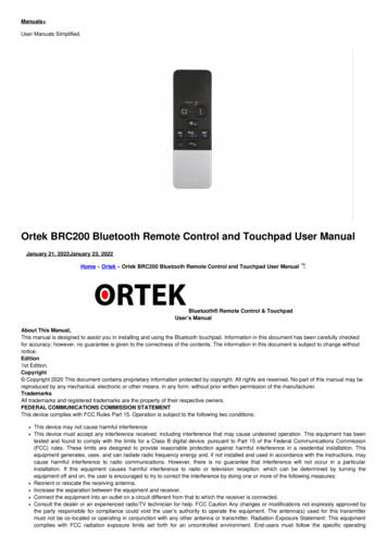
RSL10 SIPANTENNA SPECIFICATIONSThe antenna performance of the RSL10 SIP depends on the size of the ground plane on which it is mounted. Figure 4 showsan overview of different ground plane sizes with expected antenna return losses shown in Figure 5.Figure 4. PCB ground planes. 1) 50x60, 2) 40x60, 3) 30x60, 4) 25x60, 5) 12.5x60. All sizes in mm.Figure 5. Antenna Efficiency vs. PCB Size.www.onsemi.com13
RSL10 SIPFigure 6. Radiation Pattern for PCB Ground Plane 1 (50 x 60 mm)Figure 7. Radiation Pattern for PCB Ground Plane 2 (40 x 60 mm)Figure 8. Radiation Pattern for PCB Ground Plane 3 (30 x 60 mm)www.onsemi.com14
RSL10 SIPFigure 9. Radiation Pattern for PCB Ground Plane 4 (25 x 60 mm)Figure 10. Radiation Pattern for PCB Ground Plane 5 (12.5 x 60 mm)ENVIRONMENTAL SPECIFICATIONSElectrostatic Discharge (ESD) Sensitive DeviceCAUTION: ESD sensitive device. Permanent damage may occur on devices subjected to high energy electrostaticdischarges.Proper ESD precautions in handling, packaging and testing are recommended to avoid performance degradation or loss offunctionality.Solder InformationThe RSL10 SIP is constructed with all RoHS compliant material and should be reflowed accordingly. This device is MoistureSensitive Class MSL3 and must be stored and handled accordingly. Re flow according to IPC/JEDEC standard J STD 020C,Joint Industry Standard: Re flow Sensitivity Classification for Nonhermetic Solid State Surface Mount Devices. Handsoldering is not recommended for this part.For more information, see SOLDERRM/D available from http://onsemi.com.www.onsemi.com15
RSL10 SIPREGULATORY INFORMATIONFCC Regulatory and User InformationFCC ID: 2APD9 RSL10SIPThis device complies with Part 15 of the FCC Rules. Operation is subject to the following two conditions:(1) this device may not cause harmful interference, and (2) this device must accept any interference received, includinginterference that may cause undesired operation.Any changes or modifications not expressly approved by On Semiconductor could void the user’s authority to operate theequipment.Module Usage ConditionsManufacturers of products incorporating the RSL10SIP Bluetooth 5 Module are authorized to use the FCC Grant of theRSL10SIP module for their own products according to the conditions referenced in the grant.A product containing the RSL10SIP module shall bear a label referring to the enclosed module. The label shall use wordingsuch as: “Contains FCC ID:2APD9 RSL10SIP”The label of the host device shall also contain the following statement. When this is not possible, the information shall beincluded in the User Manual of the host device:“This device complies with Part 15 of the FCC Rules. Operation is subject to the following two conditions:(1) this device may not cause harmful interference, and (2) this device must accept any interference received, includinginterference that may cause undesired operation.Any changes or modifications not expressly approved by On Semiconductor could void the user’s authority to operate theequipment.”ISED Regulatory and User InformationISED ID23763 RSL10SIPHVINRSL10SIPThis device contains licence exempt transmitter(s)/receiver(s) that comply with Innovation, Science and EconomicDevelopment Canada’s licence exempt RSS(s). Operation is subject to the following two conditions:(1) This device may not cause interference.(2) This device must accept any interference, including interference that may cause undesired operation of the device.L’émetteur/récepteur exempt de licence contenu dans le présent appareil est conforme aux CNR d’Innovation, Sciences etDéveloppement économique Canada applicables aux appareils radio exempts de licence. L’exploitation est autorisée aux deuxconditions suivantes :(1) L’appareil ne doit pas produire de brouillage;(2) L’appareil doit accepter tout brouillageradioélectrique subi, même si le brouillage est susceptible d’en compromettre le fonctionnement.Module Usage ConditionsA product containing the RSL10SIP module shall bear a label referring to the enclosed module. The label shall use wordingsuch as: “Contains IC: 23763 RSL10SIP”The label of the host device shall also contain the following statement. When this is not possible, the information shall beincluded in the User Manual of the host device:“This device contains licence exempt transmitter(s)/receiver(s) that comply with Innovation, Science and EconomicDevelopment Canada’s licence exempt RSS(s). Operation is subject to the following two conditions:(1) This device may not cause interference.(2) This device must accept any interference, including interference that may cause undesired operation of the device.”The transmitter module may not be co located with any other transmitter or antenna.Un produit contenant le module RSL10SIP devra porter une étiquette du dispositif qui fait référence au module inclus.L’étiquette du dispositif devra utiliser un libellé tel que : “Contient IC : 23763 RSL10SIP”L’étiquette du dispositif devra également inclure la déclaration ci dessous. Si cela n’est pas possible, cette information devraêtre précisée dans le manuel de l’utilisateur:L’émetteur/récepteur exempt de licence contenu dans le présent appareil est conforme aux CNR d’Innovation, Sciences etDéveloppement économique Canada applicables aux appareils radio exempts de licence. L’exploitation est autorisée aux deuxconditions suivantes :(1) L’appareil ne doit pas produire de brouillage;(2) L’appareil doit accepter tout brouillageradioélectrique subi, même si le brouillage est susceptible d’en compromettre le fonctionnement.Le module émetteur peut ne pas être coïmplanté avec un autre émetteur ou antenne.www.onsemi.com16
RSL10 SIPKorean Regulatory and User Information특정소출력 무선기기(데이터통신시스템용 무선기기)제 조 자 (Manufacturer): ON Semiconductor제 조 국 (Origin): Canada제 품 명 (Product): NCH-RSL10-101S51-ACG모 델 명 (Model): RSL10SIP제조년월 (Production date): Pending이 장치는 이동전화, Wi-Fi 또는 블루투스 장치 등 무선통신장치와 매우 근접한 장소에서 사용할 경우 오작동을일으킬 가능성이 있습니다.해당 무선설비는 전파혼신 가능성이 있으므로 인명안전과 관련된 서비스는 할 수 없음.The following ID information needs to be added to the product package (application and user documentation).Korean KC Mark and Identifier as shown below. Height of KC mark is 5mm minimum. Colour preference is Navy (5PB 2/8color according to KS A 0062). Acceptable other colours are black, gold and silver. Other colours may only be used if preferredcolours are not legible for the mark. The conformity assessment certification number is to be near the KC mark. (usually below).R-CRM-oNs-RSL10SIPEuropean Regulatory and User InformationThis device complies with the essential requirements of the Radio Equipment Directive 2014/53/EU. The following IDinformation needs to be added to the product package (application and user documentation).Japanese Regulatory and User InformationThe following ID information needs to be added to the product package (application and user documentation).ID (209 J00320) and must be combined with the Giteki (MIC) Mark as specified below.www.onsemi.com17
RSL10 SIPDevelopment ToolsCompany or Product InquiriesRSL10 is supported by a full suite of comprehensive toolsincluding: An easy to use development board Software Development Kit (SDK) including an OxygenEclipse based development environment, Bluetoothprotocol stacks, sample code, libraries, anddocumentationFor more information about ON Semiconductor productsor services visit our Web site at http://onsemi.com.For sales or technical support, contact your localrepresentative or authorized distributor.www.onsemi.com18
RSL10 SIPPACKAGE DIMENSIONSSIP51 8x6CASE 127EYISSUE Awww.onsemi.com19
RSL10 SIPON Semiconductor is licensed by the Philips Corporation to carry the I2C bus protocol.Bluetooth is a registered trademark of Bluetooth SIG.Arm and Cortex are registered trademarks of Arm Limited (or its subsidiaries).ON Semiconductor andare trademarks of Semiconductor Components Industries, LLC dba ON Semiconductor or its subsidiaries in the United States and/or other countries.ON Semiconductor owns the rights to a number of patents, trademarks, copyrights, trade secrets, and other intellectual property. A listing of ON Semiconductor’s product/patentcoverage may be accessed at www.onsemi.com/site/pdf/Patent Marking.pdf. ON Semiconductor reserves the right to make changes without further notice to any products herein.ON Semiconductor makes no warranty, representation or guarantee regarding the suitability of its products for any particular purpose, nor does ON Semiconductor assume any liabilityarising out of the application or use of any product or circuit, and specifically disclaims any and all liability, including without limitation special, consequential or incidental damages.Buyer is responsible for its products and applications using ON Semiconductor products, including compliance with all laws, regulations and safety requirements or standards,regardless of any support or applications information provided by ON Semiconductor. “Typical” parameters which may be provided in ON Semiconductor data sheets and/orspecifications can and do vary in different applications and actual performance may vary over time. All operating parameters, including “Typicals” must be validated for each customerapplication by customer’s technical experts. ON Semiconductor does not convey any license under its patent rights nor the rights of others. ON Semiconductor products are notdesigned, intended, or authorized for use as a critical component in life support systems or any FDA Class 3 medical devices or medical devices with a same or similar classificationin a foreign jurisdiction or any devices intended for implantation in the human body. Should Buyer purchase or use ON Semiconductor products for any such unintended or unauthorizedapplication, Buyer shall indemnify and hold ON Semiconductor and its officers, employees, subsidiaries, affiliates, and distributors harmless against all claims, costs, damages, andexpenses, and reasonable attorney fees arising out of, directly or indirectly, any claim of pe
RSL10 SIP www.onsemi.com 3 Notice All specifications for the RSL10 System in Package are based on the RSL10 radio SoC. The RSL10 SIP data sheet . that the logic high level for the digital I/O (DIO) pads is equal to VBAT. Figures 1 and 2 show proposed layout patterns for the RSL10 SIP. The specific layout pattern used in the

![[MS-CDP-Diff]: Connected Devices Platform Protocol Version 3](/img/35/5bms-cdp-5d-220429-diff.jpg)