Transcription
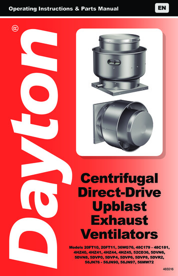
Operating Instructions & Parts latorsModels 20FT10, 20FT11, 36WG76, 48C179 - 48C181,4HZ40, 4HZ41, 4HZ44, 4HZ45, 52CD36, 5DVN6,5DVN8, 5DVP0, 5DVP4, 5DVP6, 5DVP8, 5DVR2,56JN76 - 56JN90, 56JN97, 56MW72465516
PLEASE READ AND SAVETHESE INSTRUCTIONS.READ CAREFULLYBEFORE ATTEMPTINGTO ASSEMBLE, INSTALL,OPERATE OR MAINTAIN THEPRODUCT DESCRIBED.PROTECT YOURSELF ANDOTHERS BY OBSERVING ALLSAFETY INFORMATION. FAILURETO COMPLY WITH INSTRUCTIONSCOULD RESULT IN PERSONALINJURY AND/OR PROPERTYDAMAGE! RETAIN INSTRUCTIONSFOR FUTURE REFERENCE.PLEASE REFER TO BACK COVERFOR INFORMATION REGARDINGDAYTON’S WARRANTY AND OTHERIMPORTANT INFORMATION.Model #:Serial #:Purch. Date:Form 5S6829 / Printed in USA04632 Version 6 10/2020 2004 - 2020 Dayton Electric Manufacturing Co.All Rights Reserved
Installation, troubleshooting and parts replacement areto be performed only by qualified personnel.Electrical Requirements: SAFETY /SPECIFICATIONSThe motor amperage and voltage ratings must be checked forcompatibility to supply voltage prior to final electrical connection.Wiring must conform to local and national codes.Tools Needed: Dayton Roof Curb Mounting Fasteners (8) Sealant or Caulk TachometerGETTING STARTEDBEFORE YOU BEGIN NEMA 1 (1H400, 1H401) / NEMA 4 (1H408, 1H409) Disconnect Switch Roof Curb (2RB75-2RB77, 2RB79-2RB82, 24Y860, 2ZV82-2ZV85) Ventilated Roof Curb (4HX54-4HX60, 4HX61-4HX63) Roof Curb Adapter (3AZK1-3AZK9, 3AZL1-3AZL3) Grease Collector Box (48C174) Sidewall Grease Collector Kit (56JN65-56JN69) Roof Mount Curb Hinge Kit (20CK53-20CK56, 4HX79,56JN70-56JN72) Sidewall Curb Hinge Kit (56JN70-56JN75) Wall Mounting Bracket (56JN59-56JN64) Clean-Out Port Kit (3ATV9) Damper (4HX64-4HX70)OPERATION ASSEMBLY /INSTALLATIONRecommended Accessories:UNPACKINGContents:Dayton Centrifugal Belt-Drive Upblast Exhaust Ventilator (1) Operating Instructions and Parts Manual (1)MAINTENANCE /REPAIR Inspect:After unpacking unit, inspect carefully for any damage that may haveoccurred during transit. Check for loose, missing, or damaged parts.Shipping damage claim must be filed with carrier. Check all bolts, screws, set-screws, etc. for looseness that may haveoccurred during transit. Retighten as required. Rotate wheel by handto be sure it turns freely. See General Safety Instructions on page 2, and Cautions andWarnings as shown.1TROUBLESHOOTING
Only qualified personnel should install this fan. Personnel should have a clearunderstanding of these instructions and should be aware of general safetyprecautions. Improper installation can result in electric shock, possible injurydue to coming in contact with moving parts, as well as other potential hazards.Other considerations may be required if high winds or seismic activity ispresent. If more information is needed, contact a licensed professional engineerbefore moving forward.SAFETY /SPECIFICATIONSGETTING STARTEDGENERAL SAFETY INSTRUCTIONSDo not depend on any switch as the sole means ofdisconnecting power when installing or servicing theventilator. Always disconnect, lock and tag power source before installing orservicing. Failure to disconnect power source can result in fire, shock or seriousinjury. Motor will restart without warning after thermal protector trips. Do nottouch operating motor, it may be hot enough to cause injury.power source.Do not place any body parts or objects in ventilator,motor openings or drives while motor is connected toASSEMBLY /INSTALLATIONDo not use this equipment in explosive atmospheresunless motor and disconnect are suitable for use inhazardous environments.To reduce the risk of injury to persons, observe thefollowing:OSHA requires OSHA complying guards when fan is installed within 7 feet offloor or working level.TROUBLESHOOTINGMAINTENANCE /REPAIROPERATIONUL/cUL Standards require OSHA complying guards when fan is installed within8 feet of floor or working level.21.Follow all local electrical and safety codes, as well as the NationalElectrical Code (NEC) and the National Fire Protection Agency(NFPA), where applicable. Follow the Canadian Electrical Code(CEC) in Canada.2.The rotation of the wheel is critical. It must be free to rotate withoutstriking or rubbing any stationary objects.3.Motor must be securely and adequately grounded.4.Do not spin fan wheel faster than max cataloged fan RPM. Adjustmentsto fan speed significantly affects motor load. If the fan RPM is changed,the motor current should be checked to make sure it is not exceedingthe motor nameplate amps.5.Do not allow the power cable to kink or come in contact with oil,grease, hot surfaces or chemicals. Replace cord immediatelyif damaged.6.Verify that the power source is compatible with the equipment.7.Never open access doors to a duct while the fan is running.
GETTING STARTEDSPECIFICATIONSModelMax. Inlet Temp.130 F300 FRoof/SidewallRoof/SidewallHousing MaterialSpun AluminumWheel TypeBackward Inclined CentrifugalIncludesAgency ComplianceAgency Compliance20FT10, 20FT11, 36WG76, 48C180,48C181, 4HZ40G, 4HZ41G, 4HZ44G,4HZ45G, 52CD36, 56JN76 - 56JN90,56JN97, 56MW72, 5DVP8, 5DVR2ASAFETY /SPECIFICATIONSMounting Location5DVN6, 5DVN8,5DVP0, 5DVP4,5DVP6, 48C179NEMA 1 Junction Box, , UL/cUL 705UL/cUL 762*AMCA Sound and AirElectronically commutated ventilators include motor mounted potentiometer dial to adjustspeed. Optional remote mount speed control kit 43Y140 can be purchased separately.ASSEMBLY /INSTALLATION* Ventilators are UL/cUL Listed Subject 762 (YZHW) and comply with all requirementsset forth in NFPA 96 Standard for Ventilation Control and Fire Protection CommercialCooking Operations.E53236MH12596OPERATIONMAINTENANCE /REPAIRTROUBLESHOOTING3
GETTING STARTEDSAFETY /SPECIFICATIONSBase Size (Sq.)Wheel Dia.Shaft Dia.Recommended RoofOpening (Sq.)RecommendedDamper Size (Sq.)RecommendedSpeed ControlBase Size (Sq.)Wheel Dia.Shaft Dia.Recommended RoofOpening (Sq.)RecommendedDamper Size (Sq.)RecommendedSpeed ControlTROUBLESHOOTINGMAINTENANCE /REPAIROPERATIONASSEMBLY /INSTALLATIONDimensions 6191916191943Y14043Y14048C17243Y14043Y14048C173
1/219232323—43Y140——ASSEMBLY /INSTALLATION5DVR2ASAFETY /SPECIFICATIONS4HZ40G4HZ41GGETTING STARTED48C18136WG76OPERATIONMAINTENANCE /REPAIRTROUBLESHOOTING5
GETTING STARTEDSAFETY /SPECIFICATIONSPERFORMANCEModel115V, 1-Phase5DVN61/60 —5DVN81/30 —5DVP01/20 ——ASSEMBLY /INSTALLATION———1/1548C1791/6RPMMaxBHPSones @.125" SP@ 5 .020FT11 1/4——17250.2513.8——————1300 0.06752CD36—1/2 19000.21—25000.44—Dayton Electric Mfg. Co. certifies that the ventilators shown herein are licensed tobear the AMCA seal. The ratings shown are based on tests and proceduresperformed in accordance with AMCA Publication 211 and AMCA Publication 311and comply with the requirements of the AMCA Certified Ratings Program.MAINTENANCE /REPAIROPERATIONHP—5DVP4TROUBLESHOOTINGHPModel – ECM115V, 1-Phase6
��——977929878815750OPERATION1049ASSEMBLY /INSTALLATION1.25"133SAFETY /SPECIFICATIONS.125"GETTING STARTEDCFM Air Delivery @ Static Pressure Shown.250".375".500".750"1.00".000"MAINTENANCE /REPAIRPerformance certified is for installation type A: Free inlet, Free outlet. Performance ratingsdo not include the effects of appurtenances (accessories). The sound ratings shown areloudness values in fan sones at 5 ft. (1.5 m) in a hemispherical free field calculated perAMCA Standard 301. Values shown are for installation type A: Free inlet hemisphericalsone levels.‡ 208-230V, 1-Phase† 208-230/460V, 3-Phase Motors are UL Listed for use in hazardous locations.TROUBLESHOOTING7
GETTING STARTEDSAFETY /SPECIFICATIONSASSEMBLY /INSTALLATIONOPERATIONMAINTENANCE /REPAIRTROUBLESHOOTINGPERFORMANCE CONTINUEDModel115V, 1-PhaseHP——4HZ40G1/64HZ41G N77RPMMaxBHPSones @.125" SP @5 Ft.8600.040.61/4 11400.096.517250.2912.55.6Model – ECM115V, 1-PhaseHP5DVR2A48C1808600.061/2 11400.148.217250.4816.78600.077.736WG76‡, 48C1813/4 ——————56JN81, �56JN87, 56JN97†1—56JN90†2—56JN79, 36WG77‡,56JN80‡56JN84, 56JN85‡0.250.229.83/4 5814.83/4106556JN8311340172556JN86‡, 56JN89‡ 208-230V, 1-Phase† 208-230/460V, 3-Phase Motors are UL Listed for use in hazardous 7—11400.9316.5—11401.74231
Y /INSTALLATION11801564SAFETY /SPECIFICATIONS.125"GETTING STARTEDCFM Air Delivery @ Static Pressure Shown.250".375".500".750"1.00".000"MAINTENANCE /REPAIRPerformance certified is for installation type A: Free inlet, Free outlet. Performance ratingsdo not include the effects of appurtenances (accessories). The sound ratings shown areloudness values in fan sones at 5 ft. (1.5 m) in a hemispherical free field calculated perAMCA Standard 301. Values shown are for installation type A: Free inlet hemisphericalsone levels.TROUBLESHOOTING9
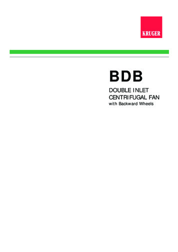
Upon receiving the product, check to ensure all items are accounted for byreferencing the delivery receipt or packing list. Inspect each crate or cartonfor shipping damage before accepting delivery. Alert the carrier of anydamage detected. The customer will make notation of damage (or shortageof items) on the delivery receipt and all copies of the bill of lading which iscountersigned by the delivering carrier. If damaged, immediately contactyour representative. Any physical damage to the unit after acceptance is notthe responsibility of the manufacturer.SAFETY /SPECIFICATIONSGETTING STARTEDRECEIVINGDo not lift by the fan hood. Avoid lifting fans in a waythat will bend or distort fan parts. Never pass slings ortimbers through the venturi of fan. Fans with special coatings or paints must beprotected in handling to prevent damage.HANDLINGASSEMBLY /INSTALLATIONLift Direct Drive unit on to the roof utilizing hooks under the horizontalsupports. Evenly space the hooks using a minimum of four lifting straps.Use a spreader bar to ensure the straps do not come in contact with theunit, see Figure 1.TROUBLESHOOTINGMAINTENANCE /REPAIROPERATIONFigure 110
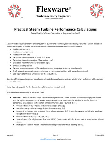
GETTING STARTEDINSTALLATION INSTRUCTIONS-General Ventilation InstallationDisconnect OptionalJunction Box StandardDamperBolt HoleCircle8" or 12" in.Wiring byOthersSAFETY /SPECIFICATIONSFigure 2 Typical RoofMounting InstallationMountingRecommendDuct andDamper SizRecommendedWall OpeningDamperRoof DeckWiring byothersRecommendedDuct andDamper SizeRecommendedRoof OpeningASSEMBLY //ASSEMBLYINSTALLATIONINSTALLATIONIf unit is equipped with a backdraft damper,it should be installed now.3.Remove motor cover. Access to the motorcompartment is accomplished by removingthe screws.4.On direct drive fans, lift and place the uniton top of roof curb using hooks under thehorizontal supports. Refer to Figure 1, page 10.5.Secure fan to curb using a minimum of eight lag screws, metal screwsor other suitable fasteners. Shims may be required depending uponcurb installation and roofing material.6.Verify power line wiring is de-energized before connecting fan motor topower source.7.For commercial kitchen the electrical supply must enter the motorcompartment through the breather tube. For other non-flammableapplications, the electrical supply can be routed through the conduitchase between the curb cap and the bottom of the motor compartment.8.Connect power supply wiring to the motor as indicated on themotor nameplate or terminal box cover. Check the power source forcompatibility with the requirements of your equipment.9.Check fan wheel for free rotation, re-center if necessary. Checksetscrew(s) for tightness.Figure 3 - RoofCurb Installation10. Check all fasteners for tightness.11TROUBLESHOOTING2.MAINTENANCE /REPAIROn the roof surface, cut an appropriate sizedhole and follow manufacturer’s instructions oncurb installation. Caulk and flash the curb toensure a water tight seal.OPERATION1.
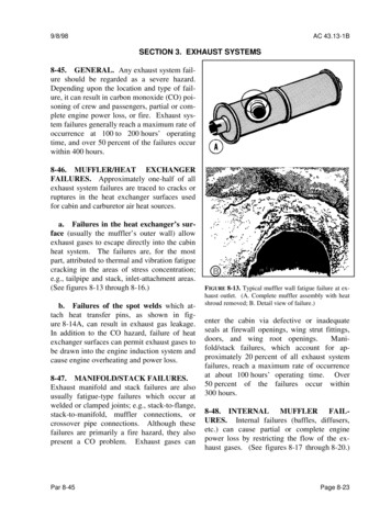
GETTING STARTEDMotor11. Mount and wire safety disconnect switchunder motor cover. Wirecontrol switches at ground level, refer to Figure Supply4. Voltage115/208-230/60/112. Replace motor cover.J-BoxL1L21-Phase, 1-Speed3-Phase, 1-SpeedSAFETY /SPECIFICATIONSMotorMotorSupply Voltage115/208-230/60/1Supply , Electronically Commutated MotorMotor to be used withLeadVariable Speedoptional variable speedSupply VoltageMotorcontrol kit installation208-230/460/60/3ASSEMBLY /INSTALLATIONJ-BoxL1L2L3Supply Voltage115/60/1J-BoxL1L2Figure 4Electrical ConnectionComply with all local codes including the NationalElectrical Code (NEC) and National Fire Protection Act(NFPA).OPERATIONInstall in accordance to NEC 70 and NFPA requirements.IMPORTANT: Exhaust ventilators used in kitchenventilation applications must have external wiring.TROUBLESHOOTINGMAINTENANCE /REPAIRNOTE: Refer to motor nameplate for wiring procedures. Refer to switchmanufacturer for installation and wiring procedures.121.Motor and ventilator must be securely grounded (bare metal) to asuitable electric ground, such as a grounded water pipe or groundwire system.2.Wire motor for desired voltage per wiring diagram on motor, refer toFigure 4 for connection wiring diagram.
1a. Curb: Cut an appropriate sized hole in the wall for either through wall(recommended) or exterior face mount and follow the manufacturer'sinstructions on curb installation.2.Mount the curb or wall bracket to the wall with a minimum of eight3/8 inch fasteners around the flange. Caulk and flash the curb or wallbracket to ensure a watertight seal.3.Curb only: If unit is equipped with a backdraft damper, it should beinstalled now.4.Lift the fan into place. Do NOT support the unit by the hoodbandduring installation.5b. Wall bracket: Orient fan so the grease trough is downward and securefan to bracket using the fasteners provided. Wall Mounting BracketSkus: 56JN59-56JN64.6.ASSEMBLY //ASSEMBLYINSTALLATIONINSTALLATION5a. Curb: Orient fan so the grease trough is downward and secure fan tocurb using a minimum of eight lag screws, metal screws or other suitable fasteners.SAFETY /SPECIFICATIONS1b. Wall bracket: Cut an appropriate sized hole in the wall for exteriorface mounting. If unit is equipped with a backdraft damper, it should beinstalled in the ductwork/wall opening now.GETTING STARTEDSIDEWALL MOUNTING INSTALLATIONFollow steps 6 through 12 of Installation instructions on page 11.NOTE: If using any type of hinging, your fan must be a minimum of 8inches away from the wall.dardf CurbUnit12inchesmax.Secure standardroof curb flangeto wall openingMinimum of(8) 3/8 inchfasteners aroundthe flangeWallStandardRoof CurbMAINTENANCE /REPAIRWall OpeningGrease TroughStandard Roof CurbWallUnitOPERATIONNOTE: Do not install your fan more than 12 inches away from the wall.Wall OpeningFigure 5 - TypicalSidewall MountingInstallation(Through Wall)GrStandGrease TroughPointed Down13TROUBLESHOOTINGHoodband
GETTING STARTEDCOMMERCIAL KITCHEN INSTALLATIONNEMA 3RDisconnect(Optional)SAFETY /SPECIFICATIONSMinimum 40 in.DischargeHeight18 in. Greasemin. TrapWelded Ductby othersmin. of 18 in.above roofdeck perNFPAExternal Wiringby OthersFigure 6Typical RoofMountingInstallationRoof DeckRecommendedRoof OpeningASSEMBLY /INSTALLATIONCommercial kitchen installations must comply with NFPA 96. Check localand national codes for these installations and consult local code authoritiesfor other specific requirements.On the roof surface, cut an appropriate sized hole and follow manufacturer’s instructions on curb installation. Caulk and flash the curb toensure watertight seal.2.If unit is equipped with a backdraft damper. DO NOT install it. Performsteps 3 - 12 of General Ventilation Installation on page 11.OPERATIONIMPORTANT:MAINTENANCE /REPAIRTROUBLESHOOTING1.14 The size of the duct must be equal to or larger than the inlet openingof the fan. To comply with NFPA 96, the fan discharge must be a minimum of 40in. (1016 mm) above the roof surface and a minimum of 10 ft. (3048mm) from any building air intake. Per NFPA 96, ductwork to an upblast discharge exhaust fan must beconstructed of and supported by carbon steel not less than No. 6 MSG(1.52 mm) or stainless steel not less than No. 18 MSG (1.21 mm) inthickness. Duct must also extend a minimum of 18 in. (457 mm) abovethe roof surface. Ensure that a minimum of 500 ft/min of air velocity through the ductis maintained per NFPA 96, clause 8.2.1.1, 2014 edition and UL 762,Issue #7, clause 6.2, October 14, 2013. The following accessories may be required by NFPA 96 dependingupon installation: Grease Trap, Hinge Kit or Hinged Base, Clean-OutPort, and Vented Curb.
Minimum duct velocities must be maintained in kitchen exhaustapplications. If a speed controller is used, ensure compliance with allapplicablecodes.EN/CF LabelEN/CF LabelPart/No: 460420Related Engr. Drwg. 2015210Part/No: 461546Related Engr. Drwg. 2012555–Important––Important–ELECTRICAL – If fan motor is NOT thermally protected, remoteoverload protection must be installed having adequate rating as tovoltage, frequency, horsepower, and full load current per phase.Where connected to a circuit protected by fuses, use time delay fuses.For supply connection use wires rated for at least 90 C (194 F).INSTALLATION – When connecting electrical power to this fan,do not restrict motor movement. Motor must have sufficientmovement for possible future belt or wheel adjustment.CAUTION – Any fan inlet or outlet that is non-ducted must beprotected by an appropriate guard.ATTENTION – Tout ouverture d’admission ou de refoulementdu ventilateur non raccordée à une gaine doit comporter uneprotection adaptée.3 in.76.2 ximumOperatingTemperature400 F460420Representation of UL ListedPower Ventilator label2.5 in.63.5 mmINSTALLATION – When connecting electrical power to this fan,do not restrict motor movement for possible future belt or wheeladjustment.Must be installed in accordance with the requirements to NFPA 96 ormust have minimum clearances of zero inches to non-combustibles,3 inches to limited combustibles, 18 inches to combustibles.CAUTION – Mount with the lowest moving part at least 8 ft(2.5m) above floor or grade level. Not required on roof mountedventilators or duct mounted ventilators provided with belt guards.ATTENTION – Monter la pièce mobile la plus basse à au moins2,5 m au-dessus du niveau du sol. Non requis pour les ventilateursmontés sur un toit ou pour les ventilateurs montés sur gaine avecprotège-courroie.461546Representation of UL ListedPower Ventilator Restaurant ExhaustAppliances label2.5 in.63.5 mm3 in.76.2 mmSAFETY /SPECIFICATIONSPowerVentilator565LELECTRICAL – If fan motor is NOT thermally protected, remoteoverload protection must be installed having adequate rating as tovoltage, frequency, horsepower, and full load current per phase.Where connected to a circuit protected by fuses, use time delay fuses.For supply connection use wires rated for at least 90 C (194 F).GETTING STARTED GREASE TRAP INSTALLATIONNFPA 96: Upblast fans shall have a drain directed to a readily accessibleand visible grease receptacle not to exceed 1 gal. (3.8L)Grease Trap MaintenanceASSEMBLY //ASSEMBLYINSTALLATIONINSTALLATIONThe polypropylene grease trap is designed to collect grease residue andavoid drainage onto roof surface. Follow all local codes, as well as theNational Fire Protection Agency (NFPA) where applicable.Regular inspection of grease trap is recommended. Depending on theamount of grease discharged through the fan, the grease trap should becleaned regularly to ensure proper operation.NFPA 96: Upblast exhaust fans shall be supplied with a hinge.Refer to listed Installation, Operation and Maintenance Manuals for partslist and specific installation instructions: Sidewall Mount Hinge KitBracket Hinge Kit - Curb Cap Sizes 34" - 46"Hinge Kit With Cables - Curb Cap Sizes 19" - 30"Check all fasteners and setscrewsfor tightness. The wheel shouldrotate freely and be aligned asshown in Figure 7.GH15TROUBLESHOOTINGFigure 7 - Wheel Overlapand Gap DimensionMAINTENANCE /REPAIRPRE-STARTING CHECKS1.OPERATIONHINGE INSTALLATION
GETTING STARTEDModelGap (inches)2.–1/41/23/32––Wheel position is preset and the unit is test run at the factory. Movement may occur during shipment andrealignment may be necessary.Wheel and inlet cone overlap can be adjusted by loosening the setscrews in the wheel hub and moving the wheel to the desired position.OPERATION3.Check wheel rotation (viewing from the shaft side) by momentarilyenergizing the unit. Rotation should be clockwise as shown in Figure 8and correspond to the rotation decal on the unit. If wheel rotation is incorrect, reverse two of the wiring leads or check motor wiring for singlephase. Fan RPM should be checked and verified with a tachometer.Correct direction of wheel rotation is critical.Reversed rotation will result in poor airperformance, motor overloading and possible motor burnout.MAINTENANCE 56JN90,56JN97Centering the wheel can be accomplished byloosening the bolts on the support pan andmoving support pan until wheel is properlyaligned. For units with drive frame mounting, loosen the bolts holding the drive frameFigure8to the vibration isolators and reposition theClockwiseAirflowdrive frame if additional movement is needed for wheel alignment.ASSEMBLY /INSTALLATIONSAFETY /SPECIFICATIONSOverlap (inches)5DVN6, 5DVN8,5DVP0, 5DVP4,5DVP6, 48C1794HZ40G, 4HZ41G, 4HZ44G,4HZ45G, 5DVP8, 5DVR2,56MW72, 20FT10, 20FT11,36WG76, 48C180, 48C181,52CD36, 56JN76-56JN8516CountercloAirflo
GETTING STARTEDOPERATIONBefore starting up or operating fan, check all fasteners for tightness.In particular, check the setscrews in the wheel hub (or the taperedbushing and pulleys if applicable).2.While in the OFF position or before connecting the fan to power, turnthe fan wheel by hand to be sure it is not striking the venturi or anyobstacle.3.Start the fan and shut it off immediately to check rotation of the wheelwith directional arrow in the motor compartment, reference Figure 9.4.When the fan is started, observe the operation and check for anyunusual noises.5.With the system in full operation and all ductwork attached, measurecurrent input to the motor and compare with the nameplate rating todetermine if the motor is operating under safe load conditions.IMPORTANT: Adjust (tighten) belt tension after the first 24-48 hoursof operation.7.Electronically commutated motors can be controlled two ways:A motor mounted potentiometer is mounted on the case of themotor to adjust the speed manually. Turn the potentiometer usinga screwdriver to adjust the speed.b.The motor includes a capped motor lead that can be connectedto a Dayton variable-speed control kit. The motor lead cap can beremoved and connected to the nine-pin motor/transformer harnesslead. Follow installation instructions provided with optional speedcontrol kit.Remote HOOTING17MAINTENANCE /REPAIRRemote Touch35YV94OPERATIONa.ASSEMBLY /INSTALLATION6. Keep inlets and approaches to fan clean and free from obstruction.SAFETY /SPECIFICATIONS1.
GETTING STARTEDInspection of the fan should be conducted at the first 30 minute and 24 hourintervals of satisfactory operation.30 Minute Interval: Inspect bolts, setscrews and motor mounting bolts.Adjust and tighten as necessary.24 Hour Interval: Check all internal components. On belt drive unit only,inspect belt alignment and tension. Adjust and tighten as necessary.MAINTENANCEDisconnect and secure to the “off” position allelectrical power to the fan prior to inspection orservicing. Failure to comply with this safety precaution could result inserious injury or death.This unit should be made non-functional whencleaning the wheel or housing (fuses removed,disconnect locked off).ASSEMBLY /INSTALLATIONSAFETY /SPECIFICATIONSINSPECTIONIMPORTANT: Uneven cleaning of the wheel will produce an out of balancecondition that will cause vibration in the fan.Installation and maintenance are to be performed only by qualifiedpersonnel who are familiar with local codes and regulations and who areexperienced with this type of equipment.Motor maintenance is generally limited to cleaning and lubrication (whereapplicable). Cleaning should be limited to exterior surfaces only. Removingdust buildup on motor housing ensures proper motor cooling.OPERATIONGreasing of motors is only intended when fittings are provided. Manyfractional horsepower motors are permanently lubricated and should notbe lubricated after installation. Motors supplied with grease fittings shouldbe greased in accordance with manufacturer’s recommendations. Wheremotor temperatures do not exceed 104ºF (40ºC), the grease should bereplaced after 2,000 hours of running time as a general rule.TROUBLESHOOTINGMAINTENANCE /REPAIRWheels require very little attention when moving clean air. Occasionally, oiland dust may accumulate causing imbalance. When this occurs, the wheeland housing should be cleaned to ensure smooth and safe operation.All fasteners should be checked for tightness each time maintenancechecks are performed prior to restarting unit. When installing fans for restaurant exhaust applications follow NFPA 96 forcleaning fans. Grease containers must be emptied at regular intervals to prevent overflow.A proper maintenance program will help these units deliver years ofdependable service.18
GETTING STARTEDREPAIR PARTS ILLUSTRATIONFOR ROOF/SIDEWALL214367(Optional Accessory,Included onUL-705 Models)DescriptionPart Number for Models:4HZ40G 4HZ41G 7321DY7321DY7421DY7412Hood Assembly U274YU194YU294YU194YY5414Isolator Kit21DZ1021DZ1021DZ1021DZ1021DY9321DY9315Support DY9121DY9121DZ4621DZ4621DW39 21DW39 VN8Qty.21DY7221DY72DescriptionPart Number for DY7521DY752Hood Assembly U204YU264YU2221DW274YU3214Isolator Kit21DY9321DY9321DY9321DY9321DZ1021DZ1015Support Plate21DZ5321DZ5321DZ3521DW38 21DY7821DY7816Wheel21DX6821DZ4421DZ5421DZ5421DW32 .No.11† Birdscreen included on UL-705 models: 5DVN6, 5DVN8, 5DVP0, 5DVP4,5DVP6, 48C179.TROUBLESHOOTING19MAINTENANCE /REPAIR4ZA27†OPERATIONRef.No.ASSEMBLY /INSTALLATIONREPAIR PARTS LISTFOR ROOF/SIDEWALLSAFETY /SPECIFICATIONS5
GETTING STARTEDSAFETY /SPECIFICATIONSASSEMBLY /INSTALLATIONOPERATIONMAINTENANCE /REPAIRTROUBLESHOOTINGRef.No.DescriptionPart Number for Models:5DVP05DVP45DVP61Cover21DW30 21DW30 21DW30 21DY732Hood Assembly 21DW41 21DW41 21DW413Motor1AGF821DW284Isolator DZ1021DV9821DZ101Support Plate21DW31 21DW31 21DW3121DZ3121DW3821DZ3316Wheel21DW33 21DW34 21DY8721EC48 21DW37 21DY9117Birdscreen21DW49† 21DW49† 21DW49†Ref.No.DescriptionPart Number for Models:56JN7956JN84 56MW7256JN971Cover21DY7421DY7421DY7421DY752Hood Assembly solator Kit21DY9321DZ105Support ef.No.DescriptionPart Number for 1DY75 21DW30 21DY7312Hood Assembly 1TL0641TL0641TL0743Y13543Y13714Isolator Kit21DZ1021DY9321DZ1021DY9321DZ0821DZ1015Support Plate21DY1021DZ5321DZ5321DW38 21DW3121DZ3116Wheel21DY0929PH7621DZ4421DW17 21DW34 78156JN7856JN83Qty.Ref.No.DescriptionPart Number for 1DY7421DY7412Hood Assembly 21DZ0921DZ7221DZ0921DZ1621DZ1613Motor43Y13843Y139
3. Motor must be securely and adequately grounded. 4. Do not spin fan wheel faster than max cataloged fan RPM. Adjustments to fan speed significantly affects motor load. If the fan RPM is changed, the motor current should be checked to make sure it is not exceeding the motor nameplate amps. 5.