Transcription
astudyf Infiltratio an Ventil ti n Impr vementsin a Multi-F mily uildinMark Em Kelly IU, Building Science EngineeringJohn Ell McQuail, Conservation Services Group, Inc.Robert O'Brien e New England Electric Services Company8The Massachusetts Electric Multi-Family Conservation program invested in the analysis and implementation of energy use reduction improvements at an eleven story building in Revere, MAe Theoretical andempirical data were developed and analyzed by Conservation Services Group, Inc, Building ScienceEngineering and New England Electric Services Company, to assess the effectiveness of energy improvements individually and collectively. A significant reduction in infiltration and ventilation heat loss wasachieved through blower door-assisted building envelope air sealing and changes to the building ventilation systems. Flow hood measurements of ventilation stacks before and after modifications revealedgreater energy savings than theoretical analysis initially indicated. This project demonstrates certaineconomies of scale that enhance investment incentives to building owners and utilities for infiltration andventilation reduction projects may exist in many elevator buildings IntroductionThe Revere Massachusetts Housing Authority owns,operates and manages the 7500 square foot per floor,eleven-story, one hundred six (106) unit apartmentOUIJ[CU11UZ with a common areas annex, that is the subject ofthisA parking garage, cafeteria, recreation andactivities center and laundry facility on the ground- andfirst floor levelsan the domestic and commonarea facilities necessary for the elderly tenants living onthe upper ten floors Steel columns support the structuralconcrete floor slabs and roof deck. Exterior walls areinsulated with three and one-half inches of fiberglass battsfinished with aribbed brick exterior and foil-backedgypsum wall board interior. Roof insulation consists ofone and one-half inches offoam under the tar androofwith the same thickness of acousticalbatt insulation in theWindows are fixedglass on the first floor with sliding insulatednonthermal break windows in the elevator lobbies Thisis an 11with smalltwo roomThere is a central elevator lobby/shaft and two stair wells on opposite ends of the building is 8with a 1-1/2 foot plenum abovetheand a concrete floor slab above for a total floorto floor height of 9'4" The building has a parking garageunder the first flOOf The total height from the roof of thegarage to the roof of the building is 103 feet and theabove grade is roughly 110 feet The first floor hasCasekitchens, common and administrative offices, but nounits.central ventilation systems for the main buildingwith exhaust fans on the main roof consisted of: onecafeteria kitchen hood belt-driven centrifugal upblastdischarge exhaust blower (1200 cfm), one belt-drivencentrifugal horizontal discharge exhaust blower(1080 cfm) for trash fOOms, the mail room and janitor'scloset, one belt-driven centrifugal horizontal dischargesmoke exhaust blower (2250 cfm), and eight kitchen(1237 cfm) and six toilet (1273 cfm) belt-driven centrifugal horizontal discharge exhaust blowers to service the106 apartments A.JJ't.ll.lo,,7IlYJLA.Jl.F-oAnother eleven4-3600 cfm) dome type beltdriven centrifugal exhaust fans on the main roof wereinstalled as part of the make-up air system. Every apartment has a motorized damper operated by a light switchin the living/bed room. The exhaust duct is connected tocommon duct risers, so that each occupant could controlair exhausted through these dome fans from their apartments. None of the occupants nor the maintenancepersonnel were aware of the purpose of the switch.Though this building is in an urban setting, the surroundbuildings are all two or three stories in height. It isonly a few blocks from the shore, and completely exposedto winds from aU directions The control tower at Logan of Infiltration and Ventilation ImJrJr(.ve'mE nts",,.,,, . . 2",127
is visible from the top of the building only about1 mile away" This makes the use of Logan weather dataveryThe average wind speed at Logan is18.5 MPHe.0,Ito''"'' . '"Multi-blade gravity operated backdraft dampers on severalof the fans were still operating. The dampers were thesimple gravity backdraft multi blade type, and as gusts ofwind occurred, the dampers would open to their limit, andslowly close after the gust died down. Flow hood testsshowed that the air flow continued in the absence of wind,but more than doubled as the gusts occurred.ethodologyfield ConditionsTheoperable roof mounted ventilation fan during theinitial site visit was the cafeteria kitchen hood exhaust. Allbut five of thebackdraft dampers installed on allvent sets wereor "frozen" in aopenFour of the dampers were tapedclosedmaintenancedue to excessiveilieandcoastal winds at the site"""' .' . 2." . .easuresBlower door tests wereto characterizeand todemonstrateaftet· weatherization. All exhaust airinlets weresealedcrews duringblower door tests, butairtests were performed before the ventilationwere made,so there was some information towith modellingventilationAn infrared scan was alsowhichtoairsites and1i""' .,for insulation. As shown in Table 1, theaveragerate at 50 Pa was 532 CFMeAfterthe average rate was 449 CFM - areduction of 15 %" The averagecoefficient forthe blower door tests" was 38 after airwith anfi, of .633 'rhese values were used with theAlberta Infiltration Modelinfiltration modelto estimate stack lossestheventilationand to estimate annual energydue to weatherizationGna.'ll"1"n-.lC4'Mn' ::ll fi.JIU'-" . ".,.,.Indoor airtests: After aU ventilation systemwere inand with fans operating at lowto ascertain thea C02 test wasventilation. The C02 levels were allestablishment ofbelow 550 PPM or about half the ASHRAE Standard 62maximum level of .1 % or 1000 PPM.2 128 Kelly et al.wMultifamily Ventilation DiscussionGeneralInfiltration studies in multifamily buildings are typicallycharacterized as row houses, shaft-type, or story-typeconstruction. The difference between shaft and story-typerelates to the relative transmigration of airbetween the building components with infinite leakagebetween floors for the idealized shaft-type, and zero forthe idealized story type. Although there is no doubt thatthis building is more aptly described in the story-typecategory, the large number and variety of shafts(elevators, stairs, chutes, and ventilation) brings therelative permeability between floors to a high value. Theshaft-type building would have no resistance to stackdriven air flow and the neutral pressure zone would be atmid-level. The story-type would have a neutral pressurezone on each floor independent of the other floors butin absolute terms, by the height above gradeo Thisbuilding is in between, and before air sealing would havebeen more permeable, thus more shaft-like. As thebuilding wasthe apartments became lesspermeable to both inside corridors (hence stair and
elevator shafts) and to the outdoors. Stairwells, leakage atthe garage ceiling level, and elevator shafts were sealed.The remaining strong shaft connection is through theventilation shafts. In analysis and modelling, it is desirableto treat these ventilation shafts independently in order toestimate their effects and the value of closing off some ofthe shafts.Each unit had three separate ventilation systems and fourexhaust grilles (two were connected to a common mechanical damper operated by a manual switch), an attempt wasmade to estimate the approximate ventilation rate in theinitial condition. At that time nearly all of the fans wereinoperable, and all were turned off, so any ventilation wasdriven by natural convection. The number of shafts,including ventilation, elevators, trash chutes, and stairsmakes precise knowledge of pressure difference and airflow impossible, but some generalizations are possible.odeUingWeto estimate the volume of airnatural convectionthe ventilationducts. None of the available methods was found to bereasonably accurate because of the need to estimate factorswithout real knowlof thesituatione ForeX lmJ)1e, the ASHRAE flue calculation methods (rererlenc eare based on sound physicalbutestimation of the resistance of the duct to air flowAs builtgave little information about theof the ventilationand it was difficult to guess eventhe number ofmuch less the resistance of thebroken daInp rs.9This gives a frictionless flow of 478 ft/min in an idealizedduct. If such a duct were 2 ft square, the flow would be956 CFM. Though this estimate for stack effect ventilation is based on boundary conditions that are idealized, itgives us a maximum for comparison with our measurements and other estimateseThe AIM model appeared to offer useful information forunderstanding some of the parameters surrounding thenatural ventilation, because it considers the flue as adiscrete component of exfiltration This model treats theflue as a separate leakage site with the outlet above theroof and a shelter coefficient that may be different fromthat of the building. In most important respects, the fluein the AIM model is identical in characterization to theventilation ducts in the Walnut Avenue building. The flueis assumed to add to the air exfiltration when the furnaceis off and to do so at normal house temperaturee Althoughthe model is designed for single family use, it is based onfirst principleswith the modifications usedshould give a reasonable prediction of natural flowvolumes for taller buildings. Primary differences are thepresence of fans andwhich add resistance to theflowthis was negligible in the dome fans), andtheof the building which was accounted for byillClepen(:lel1ltivthe infiltration at each leveL'8".6.", '8"'11 V'I,In order to model the vent stack losses relative to theof thethe stack reference pressure wascalculated for theof each floor independentlyas well as for the averageand mid-height of thesixth floor" Thefor the stack reference pressureis:Psestimates ofBernoulliwas used to estimate the average"Plnf"11n.r for a frictionless ductat the averageof the tnuIC1tD2: Z2 ZlgHwherePsR l!"ll!'::::::H gT Stack reference pressureairreferencegravitational constanttemperaturewherePI P2W::::::Zl::::::Z2::::::pressure at datum level::::::Vi V2::::::0are for indoor and outdoorWhile the AIM model is similar in manyto theSherman Grimsrud (reference 4) model, the basic difference being that AIM uses an additive flue factorapower law to estimate wind induced infiltration. The Ffactor is added to the general stack effect leakage which iscombined with the wind effect leakage totheoverall airThefor is: gand the . ., . .,J . '. i andconditions.Caseof Infiltration and VentilationImJr:;r, vemE ntS'"""
F :: n Y(Bf-l) «3n-l)/3» (1-(3(Xc -X) 2 R1-n)/2Bf l»wherenYBfRX CFM, is lower than the 20% flue fraction case by4. 3 CFM, or about half. Extrapolating to all ten occupiedstories, this would predict 43 CFM for the exhaust ventsystem.flow exponent (. 66 typical)flue fraction relative to total leakageratio of flue height to ceiling height"ceiling-floor sum""ceiling-floor difference"and Xc is the critical value of the ceiling-floor differenceat which the neutral plane is at ceiling level.R is calculated from the sum of the ceiling and floor leakage coefficients divided by the total leakage coefficient.X is similar but calculated from the difference rather thanthe sum. Y is the ratio of the flue leakage coefficient tothe total leakage coefficient.The range of predicted air flows is fairly narrow in therange of interest, namely for flue fractions from 1 to . 4.It seems likely that the leakage due to the flue would beless than half but more than 10% of the overall leakagefor theAs shown in Table 2, the air flowcalculated for this range is between 1 and 8 CFM perAnother flue relatedthe ratio of flueto rooma similar range of values as itwas varied from 1. 5 (topto 10. 5 (second floor) . InTable 1 the calculated air flows for eachareas weB as the averagee Given the lack of varithe sixth floor was taken as the measure forand the infiltration was calculated for thatlevel with no ventilation duct assumede The3. 2D. .:. . '.".:.'.:·: C.:)./. .' . ::.:::.::' . :'. . . .: :. : i: X''.:.:.:./·i:::\: /:/\:--]IAIResults for Multifamily Buildingsl"'Ua.U.V\.l ll the AIM model was instructive in focusing onthe duct losses from the apartments, in this case, themodel suffers from theof complexity in estimating the effects of many often unmeasurable parameters.The model does not seem to be sensitive to some of theassumptions about the flue or duct itself, such as itsrelative height or percentage of leakage relative to totalleakage, but other parameters are criticaL One suchvariable is the discharge coefficient, usually in the rangeof 125 in residential buildings (though it varies greatly).In this building it averaged 38, which had a large effecton the total estimated ventilation system leakage. With theoriginally assumed 125, the ventilation leakage wasestimated at 14 CFM, while at C 38, the ventilationleakage was estimated at 4.3 CFM per apartment. Sincethe measured ventilation per apartment was 726 CFM, thedata used don't reflect the ventilation or the model isma.decalla1te for high rise multizone buildings. It is likely
that both are true, since we don't have measurements ofthe flow coefficient or exponent for the apartments withthe ventilation systems open.Althoughthe ratio of vent leakage to total leakage,enters into the wind coefficient, Bf is not used in thesingle family calculation model because its effect isconsidered negligible. This may not be true for this highrise building where Bf may be as high as 10.5 whiletypical values of Bf are around 1. 5. Nevertheless the AIMmodel shows a stronger wind dependence than the LBLmodel and appears to more accurately model the winddependence in residences with flues.It was clear, from observations of gravity damper openings and from measurements of air flow at the roof exit ofthe fans, that wind pressure had a great deal to do withthe flow rate. Flow rates increased by roughly 30 % duringwind gusts during the first test period. The estimatedaverage wind speed was 12 MPH, but the velocity rangedfrom nearly zero to over 15 MPH. Nevertheless, stackeffect is the dominant driving force, with the calibratedlowest readingno wind), for ventilation volumefrom one stack at 0and the average calibratedlowestfor seven fans at 40 CFM.switch, and removal of the ineffective Hving-/bedroomdome fans with weatherproof enclosures installed on theroof openings. These changes produced a much more reliable and effective ventilation system with noticeably lowernoise levels (at both high and low speeds) on the topfloor, and reduced overall heat loss from the building dueto air infiltration and "stack" effect The fans are nowbeing run at low speed. only, which produces air flowrates of from 30 to 50 CFM in both the kitchens andbaths.The final installed cost of this project was 43,500. 00and electric energy use for the new fans is estimated at5655 kwh per year running at low speed (8760 hoursoperation). The electric use for the original fans wouldhave been 40843 kWh if an fans had been running asdesigned. The original fans had power factors around e59,while the new fans had power factors of 65 and were runat low speed.Like many conservationthe real payoff here is innon-quantifiable terms: in this case the comfort of betterindoor air quality and lower sound levels at the upperfloors. However, it is likely that in the long run the fanswould have been replaced and it is valuable to considerthe savings in electriccosts from thespecifications to the fmal actual operating conditions withall of the dome fans removed and all of thecagefansat lowl"'ll't"1n'11"HlIlluResultsElectrichn Wfil%BSavings AnalysisThe ventilation fans were notin the initialcondition - most were broken orbut because of therelative "leakiness f8 of thethere was nonelrcelved need for the ventilation system,some ofthewereand cooking and toilet odorswere both detectable andoccupantshad noof theof the mechanicalclosed off theroom and bedroomUU.est.lOI1S about the usual switchopenled to ttl didn't know what that switchthe switch didin most cases, sincetheoften didn'tthe fans wereandnatural ventilation was weak at thein all themeasured. cases.Themodificationsandto theventilationwere: adding workabletwofans with vibration isolation connected to thekitchen and bathclosure motorizedQaltnpers which are both interlocked with the respectivefanand with aoverrideIN'llIf'V'V'Il1!1'''11 .n l'''Il InfiltrationKe UI'[SAlthough the building is too large to get an accuratequantitative infiltration reading with a blowertenants and experienced air sealing crews oftencommented on the excessive drafts in theTheair leakage data collected on site alsodemonstrated that a comprehensive air sealing program,blower door induced air leaks as indicatorsshould be implemented.Table 1 shows the pre- and post- air sealing program datameasured with the ventilation systems sealed off It wasdifficult to achieve adequate pressure for accurate blowerdoor tests with the vents open. Also, the measured flowcoefficient,averaged 38 with an average flowexponent, n, of .633 weatherization The average savings of 83 CFMso win result in an annualsavings of approximately 9.6 CFM perFor thetotal building this will result in a savings of 1035 CFMresult1LD2 in a calculated savings of 26506 kWh per year.Case Study of Infiltration and VentilationImJ,'Ji'OVelneI1ts.,,,,,,M2. 131
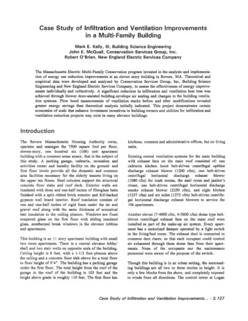
Ventilation ResultsMeasurement of exhaust air flow at the roof and in theapartments that made up the stacks leading to each of thefans showed a great discrepancy between the sum of theapartment exhausts and the amount of air exiting the roof.Duct leakage is assumed to make up the difference, andmost of this leakage occurs in the ceiling plenums abovethe apartments. Figure 1 shows the roof measured averagenatural (fan off) air flow through the centrifugal fansserving the baths and kitchens, and through the dome fansserving the bedrooms and Hvingrooms. For domes 18 and20, the air flow averaged 680 CFM. In contrast, theapartments connected to these fans ranged from 0 to 57CFM with an average of 13 CFM. In this case, the greatmajority of the substantial leakage was coming fromlocations outside the intended apartments.The initial measurement of the exhaust fans showed anaverage natural convection loss of 97 CFM for thefans with gravity dampers as found. Thedomes, which were connected to the Bedroom-Livingroomwith the mechanicalaveraged 729 CFM. Aftersealing the domes offwith insulated metalcaps, there remained some air flow through the ventilationopenings in the living rooms and bedrooms of theapartments. This attests to the conclusion that there islarge scale duct leakage between floors.Measurements of the centrifugal fans after retrofit withnew, two speed fans and mechanical dampers showed thatthe average fan-off leakage was reduced from 97 to43 CFM. On low speed the average CFM was 496 CFM,and at high speed, 1150 CFMs It is instructive to note thatthe average CFM with the new fans on low speed is lessthan the pre-weatherization air flow of 729 97 for thetwo fans perwith the previous fans switchedoff.The heat loss through the 11 dome fans averaging729 CFM would total 190144 kWh per year. All of this ispresumed saved, sincewere completely closed off atthe roof. For the 15 rectangular fans, the air volumeincreased from an average of 97 CFM to 496thisresulted in a net increase for these fans of 5985 CFM.The net added heat load would be 141914 for thefans. The overall savings would be 48230kWh per year in electriceven with the new fansaU the time."lI"'1IlII'&"ll'lnll'll"l 'lB'AIRFLOWo10020030040050060012 57 19BATH AND KITCHEN FANSZ 23ZQ 26 ZU (jju:JQLIVING ROOM AND BEDROOM FANS 12C/)13 18201 Measured Flows at Roof700800900
Total Savings Finally, if the electricity needed to runthe new fans is subtracted from the heating energysavings, the net savings is 42575 kWh/year. Adding in thesavings from the infiltration reduction in each apartmentof 26506 kWh, gives us a total savings of 69081 kWh peryear.0ConclusionsExperience with this ventilation system redesign andretrofit suggests strategies for future work to improveventilation system in existing and new buildings.1. Many multifamily buildings have excess ventilationbuilt in due to oversizing. It may be possible to reducethe infiltration losses by selectively reducing overventilation.2. Savings can be achieved in both fan electric consumption and in heating and cooling energy, whileimproving air quality.3. It would be useful to have blower door tests donewithout sealing ventilation grilles in order to establisha baseline for reduction of ventilation The initialassumption that the ventilation system would remainunchanged turned out to be wrong in this case. Inaddition, the savings calculated as a percentage will besmaller, since both the baseline and the postweathetization leakage win be larger. Savings in CFMshould be approxilnately the same004. Selection of fans must pay strict atten.tion to noiseandshould bebuffered toreduce vibration and duct-borne sound.5.in moreapproach is to use variable speed or two speed fansand adjust the ventilation rate for each apartment.6. Sealing of ducts against infiltration is important, Thecurrent trend toward smaller PVC pipe and flexibleduct for ventilation duct appears to be promising. Inthis building, more air was vented from betweenfloors than from the apartments.7. The use of mechanical dampers in multifamilyventilation systems is a complete waste of money.Provision of adjustable outlets, particularly those withsound attenuating capabilities, is far more useful.8. The sensitivity of the AIM model to the choice ofvariables suggests that considerable work needs to bedone to characterize multifamily buildings in terms ofkey parameters, and that the model itself may need tobe modified for multifamily purposes.ReferencesFeustel, H.E., Zuercher, C.R . C. Vllcke nSlDn,Grimsrud D. T., and Lipschutz, R. Temperature andWind-Induced Air Flow Patterns In a Staircase. LBL1985 LBL-14589.ASHRAE bQlllPDlent Hatldb()olc. 1988 ch 26.2.Walker, I.S. andDoJ. Including Furnace FlueLeakage in a Simple Air Infiltration Model, AirInfiltration Review, VoL 11, #4 Sep. 1990.Sherman, MoH. and Grimsrud, D.T. Infiltrationpressurization Correlation: Simplified Physical ModeHing.ASHRAE Transactions 86(2):778advanced control strategies may be usefulaCaseof Infiltration and VentilationImjor(n'e'mE nt;s.tJ .
(1080 cfm) for trash fOOms, the mail room and janitor's closet, one belt-driven centrifugal horizontal discharge smoke exhaust blower (2250 cfm), and eight kitchen (1237 cfm) and six toilet (1273 cfm) belt-drivencentrifu gal horizontal discharge exhaust blowers to service the 106 apartments Another eleven 4-3600cfm) dome type belt