Transcription
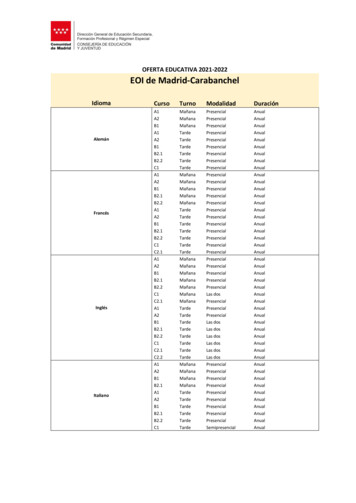
Document 473681Vari-Green Motor and Controls Installation, Operation and Maintenance ManualPlease read and save these instructions for future reference. Read carefully before attempting to assemble, install,operate or maintain the product described. Protect yourself and others by observing all safety information. Failureto comply with these instructions will result in voiding of the product warranty and may result in personal injuryand/or property damage.Table of ContentsReference part number listed in chart to locate specific motor information page number.* RPMHPVoltage1/15115-120/300-1750208-230Pg.0-5V Only3284475Pot 3180043.10-10V Only3113523.1Pot Only311353115/208350-1750230/2771/6MotorPart 0-25003ControlMethodMotorPart No.4.00-10V Only3103076.5Pot /0-10V328178410.10-10V Only30902610.1Pot .4Pot/0-10V316498311.30-10V Only31030611.3Pot 11.0/7.0/6.3Pot/0-10V32813240-10V /0/10V3281794Pot 042056.20-10V Only3090255.5Pot Only3090283137153310359115208-24012208-240 300 - 1725 TEFC* Actual maximum RPM may vary. See RPM column in chart on3page 11 for specific motor and fan 240300-1725ODP4.2Pot/0-10V3132353Controls. . . . . . . . . . . . . . . . . . . . . . . . . . . . . . . . . 7-11277350-1725ODP3.3Pot/0-10V3164973Maximum RPM Table . . . . . . . . . . . . . . . . . . . . . . . . 121/2 115RangeTENV3.51/3Encl.115311731Pot/0-10V* een Motor and Controls1
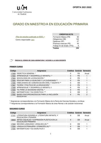
Vari-Green MotorThe Vari-Green Motor is an electronically commutated(EC) motor that uses AC input power and internallyconverts it to a DC power supply which provides an80% turndown capability and increased energy savings.Features, Operation and Wiring, andTroubleshootingFeaturesSoft start – All motorsfeature soft-starttechnology whicheliminates inrush currentat start-up. The motorswill reliably start at anyspeed setting.Overload protection – If the motor becomesoverloaded, it will automatically reduce its speed until itis no longer overloaded. This means that the motor willnever operate in the “service factor” which is possiblewith many AC motors.Locked rotor protection – If the motor ever encountersa locked-rotor scenario, the motor will automaticallyshut itself down. It will try to restart up to 3 times, and ifafter the 3rd time the motor will still not rotate, the motorwill not attempt to start again until power is cycled.NOTEWhen using a clamp meter to measure input ampdraw, the meter must be capable of reading anon-linear current. Erroneous readings will occurotherwise.Thermal protection – The motors have a one-shot fusethermal protector. This is meant to protect the motorfrom a severe temperature rise. Additionally, the motorshave on-board temperature sensors which will reducethe speed of the motor should it become too hot. Thefuse is used as a last resort to prevent a fire.WARNINGTo reduce the risk of fire or electric shock, do not usethis motor with any solid-state speed control device.Fig. 1RPM measurement – The motors have a small shaftextension on the end of the motor to measure motorRPM with either a contact or optical tachometer.0-10 VDC External connection with factory mounted transformer (See page 4 for details)Transformer Assembly100 ft. or lessWhiteBlackRedCOM24V0-10VCOM24V0-10VLow voltage, route awayfrom high voltage linesand/or use shielded cableN.C.COM.N.O.TO REMOTE DEVICEPROVIDED BYOTHERSAuxiliaryContactControlMotorTrip Point 1.85VDCContact Rating:10A @ 24-240VAC5A @ 30VDCGreen indiator light—Power presentTRANSFORMER2x4JunctionBoxFactory WiringField Wiring115/230 VAC inputto match motor name plate2Vari-Green Motor and Controls
Operation and Wiring- Potentiometer Dial OnlyPart Numbers Covered in this Section309028309029310108310475310476311353These motors feature a potentiometer dial on the motorfor speed adjustment. A small screwdriver can be usedto make the speed adjustment. To increase the speed,rotate the dial clockwise. To decrease the speed, rotatethe dial counterclockwise.The motor is pre-wired at the factory and cannot bechanged inside the motor. Connect single-phase powerat the voltage listed on the nameplate.These motors cannot be converted to receive a remotecontrol signal – a different motor is needed. Pleaseconsult the factory.Operation and Wiring- 0-10V Input OnlyPart Numbers Covered in this Section309025309026310107310306310307311352These motors will accept a 0-10 VDC control signal forspeed control. From 0-1.9V, the motor will be off, andwill operate in the 2-10V range. 24 VAC/DC power isalso required for operation. The motor will consume0.7VA at 24 VAC or 25mA at 24 VDC. A factory mountedtransformer is available to supply this voltage.(See Fig. 1)Dial on Motor – A small screwdriver can be used tomake the speed adjustment. To increase the speed,rotate the dial clockwise. To decrease the speed, rotatethe dial counterclockwise. There is no need to connectthe control wires.0-10 VDC signal – The dial on the motor must berotated fully clockwise to achieve the full speed range.If this is not done, the dial will act as a maximum speedlimiter.From 0-1.9V, the motor will be off, and will operate inthe 2-10V range. 24 VAC/DC power is also required foroperation. The motor will consume 0.7VA at 24 VACor 25mA at 24 VDC. A factory mounted transformer isavailable to supply this voltage. (See Fig. 1, page 2)A low voltage wiring harness is needed to supply the0-10V signal to the motor. This harness is available fromthe factory if conversion is necessary.Low Voltage Harness Part NumbersTypeUse with Motor18 in. long36 in. long3-pin311731, 3103593844313844329-pin311377, 311812,311388, 312359,312360, 312361,312362, 312619,313233, 313234,313235, 313712,313713, 313714,313715, 314534,314945, 316495,316496, 316497,316498, 316499,317706, 317707,317708, 317709,317886, 317887384804384805The motor is pre-wired at the factory and cannot bechanged inside the motor. Connect single-phase powerat the voltage listed on the nameplate, along with the0-10 VDC and 24V signal for speed control.NOTE: The motor will not operate without the propercontrol voltages.Operation and Wiring- Potentiometer Dial and 0-10V InputPart Numbers Covered in this 9317706317707317708317709317886317887These motors have both a potentiometer dial on themotor for speed adjustment AND have the ability toaccept a 0-10 VDC signal for remote speed control.NOTEThe 9-pin connector on the motor contains 6 wires.The red, black and white wires are used for theexternal control signal and the other three are used forfactory initialization and programing.0-10V Analog input connectionRed 0-10 VDCWhiteCommon*Black 24 VAC/DC* Common is shared between both 24V powerand 0-10V signal.The impedance of 0-10V circuit is 12KΩThere is a 4 second delay between the application ofpower and the motor starting.The motor is pre-wired at the factory and cannot bechanged inside the motor. Connect single-phase powerat the voltage listed on the nameplate. If remote controlis desired, connect the 0-10 VDC and 24V signal forremote speed control. Vari-Green Motor and Controls3
TroubleshootingMotor does not operate1. Check all wiring connections to ensure they arecorrect and secure.2. Verify that all voltages are present at the motor,including 24V and 0-10 VDC, if applicable.3. Make sure that the fan wheel will rotate freely andthere are no foreign objects in the wheel. If fan wheeldoes not rotate freely, disconnect power from themotor and adjust the wheel or housing until thewheel can freely rotate. Apply power and the motorshould restart.4. If motor has both the dial on the motor and 0-10 VDCcontrol option, control wiring issues can be testedby disconnecting the control wires from the motor.The motor should then operate using the dial on themotor for speed control.Motor will not reach maximum speed1. Make sure dial is rotated full clockwise, if applicable.2. Make sure motor is receiving 10 VDC, if applicable.3. There are some motor/fan combinationswhere the motor may not reach nameplateRPM. See Max RPM table on page 11 for themaximum motor speed for your application.Factory Mounted Transformer (Fig. 1, page 2)A factory mounted transformer is available to supply24 VDC power to the motor when the 0-10V signalis by others. This transformer has the capability topower a remote device if desired. The power availableto a remote device is 400mA at 24 VDC. If the remotedevice is powered by a different source, connect theanalog output to the 0-10V and COM terminals of thetransformer. This will pass the signal through to themotor.WARNINGDo not connect an external 24V supply to thetransformer's control terminal labeled 24V. If theexternal device providing the 0-10V signal is poweredelsewhere, this terminal can remain unused.Operation and Wiring- Potentiometer and 0-10V InputPart Numbers Covered in this 173328174328178328179Motor part numbers 318003, 318004 – The motor isprewired at the factory and cannot be changed insidethe motor. Connect single-phase power at the voltagelisted on the nameplate.Motor part numbers 318013, 319356, 319357, 320587,320588, 320589, 320590, 328128, 328129, 328130,328131, 328132, 328133, 328173, 328174, 328178,and 328179 – The motor is prewired at the factory andcan operate on 115v up to 277v. Operating voltage ischanged via voltage red jumper wire.Voltage jumper – For 115v the red jumper wire onthe side of the motor must be connected (closed).For 208v-277v operation the red jumper must bedisconnected (open). If disconnected, red jumperwire has 120 VAC potential. Ensure leads are capped/covered.Dial on Motor – A potentiometer (PN 385806) canbe plugged into the 9-pin connector of the motor. Toincrease speed, rotate the dial clockwise. To decreasespeed, rotate the dial counterclockwise.0-10 VDC Signal – From 0-1.9V, the motor will be off,and will operate in the 2-10V range. A low voltagewiring harness is needed to supply the 0-10V signal tothe motor. The harness is available from the factory ifconversion is necessary.0-5 VDC Signal – From 0-0.9V, the motor will be offand will operate in the 1-5V range. A low voltagewiring harness is needed to supply the 0-5V signal tothe motor. The harness is available from the factory ifconversion is necessary.Type9-pinLow Voltage Harness Part Numbers18 in.36 in.Use with Motorlonglong385822318003, 318004, 318013, 385821(0-10 VDC(0-10 VDC319356, 319357, 320587,only)only)320588, 320589, 320590,328128, 328129, 328130, 386518 386519(0-5 VCD328131, 328132, 328133, (0-5 VCDandand328173, 328174, 328178,0-10V DC0-10V DC328179compatible) compatible)NOTEThe 9-pin connector on the motor contains 6 wires.The yellow, orange, red and white wires are used forexternal control. The other two wires are used forfactory initialization and programming.0-10V Analog Input ConnectionRedWhiteGreenBlack 0-10 VDCCommon 0-5 VDC Signal5 VDC SupplyThese motors have the ability to accept a plug-inpotentiometer for speed adjustment AND the ability toaccept a 0-10V signal for remote control.TroubleshootingThere is a 4 second delay between the application ofpower and the motor starting.1. Verify the motor is wired correctly and all connectionsare secure.4Vari-Green Motor and ControlsMotor does not operate
2. If using dial on motor, verify the potentiometer is fullyseated in the 9-pin connector.3. If using 0-10 or 0-5 VDC, verify that all voltages arepresent at the motor.Motor does not reach maximum speed1. Make sure dial is rotated full clockwise, if applicable.2. Make sure motor is receiving 10 or 5 VDC, ifapplicable.3. There are some motor/fan combinations where themotor may not reach nameplate RPM. See MaxRPM table on page 11 for the maximum motor speedfor your application.4. Make sure black wire is disconnected when using0-10 VDC.Operation and Wiring- 0-5V InputPart Numbers Covered in this Section328447328448Motor PN 328447 has the ability to accept 0-5V signalfor speed adjustment via a 0-5V dial on fan, PN 386512.Motor PN 328448 has the ability to accept a 0-5Vsignal for speed adjustment via a plug-in potentiometerPN 385806.There is a four second delay between the application ofpower and the motor starting.Motor part numbers 328447, 328448 - the motor isprewired at the factory and can operate at single phase115-120V or 208-230V. The motor detects the incomingvoltage and automatic switches adjust for it inside themotor. All that is required is to connect single phasepower at the voltage listed on the nameplate.Dial on Motor – A potentiometer (PN 385806) canbe plugged into the 9-pin connector of the motor. Toincrease speed, rotate the dial clockwise. To decreasespeed, rotate the dial counterclockwise.0-5V Dial on Fan – From 0-1V, the motor will be off andwill operate in the 2-5V range. The low voltage wiringharness is built into the design of the motor PN 328447.NOTEThe 9-pin connector on the motor contains 3 wires.The green, white and black wires in the whitejacketing are used for external control.0-10V Analog Input ConnectionGreen 0-5 VDC SignalWhiteGroundBlack5 VDC SupplyTroubleshootingMotor does not operate1. Verify the motor is wired correctly and all connectionsare secure.2. If using dial on motor, verify the potentiometer is fullyseated in the 9-pin connector.3. If using 0-5V dial on fan controller, verify that allvoltages are present at the motor. Motor does not reach maximum speed1. Make sure dial is rotated full clockwise, if applicable.2. Make sure motor is receiving 5 VDC.Part Numbers Covered in this Section310420311156FeaturesSpeed control These motors can becontrolled by eithera dial on the motoror a 0-10 VDC signalfor remote control.Soft start – All motors feature soft-start technologywhich eliminates inrush current at start-up. The motorswill reliably start at any speed setting. There will be upto a 30 second delay between the application of powerand the motor starting. The motor will "rock" back andforth upon startup as part of its normal operation.Overload protection – If the motor becomesoverloaded, it will automatically shut itself down. Themaximum programmed motor speeds have beenselected to prevent this from happening in normaloperation.Locked rotor protection – If the motor encounters alocked-rotor scenario, it will automatically shut itselfdown. It will try to restart up to 3 times, and if after the3rd time the motor will still not rotate, the motor will notattempt to start again until power is cycled.Thermal protection – The motors have an automaticreset thermal protector. This is meant to protect themotor from a severe temperature rise.RPM measurement – The motor RPM can bemeasured by removing the cooling fan cover and usinga contact or optical tachometer. Be sure to replace thecooling fan cover when finished.Reversible rotation – The motor direction has beenpre-set at the factory for the rotation of the fan but canbe reversed if necessary.Operation and WiringThese motors can be controlled by either a dial on themotor or a 0-10 VDC signal for remote control. Themotor will be supplied from the factory with the correctaccessory depending on what was ordered.Dial on Motor - Turn the dial with your fingers to adjust.To increase the speed, rotate the dial clockwise. Todecrease the speed, rotate the dial counterclockwise.Turning the dial full Counter Clock Wise will turn themotor off.0-10 VDC Signal - From 0-1.9V, the motor will be off,and will operate in the 2-10V range. This motor does notrequire 24V power for operation.Vari-Green Motor and Controls5
0-10V Analog Input ConnectionRed 0-10 VDCWhiteGroundWiring1. All high and low voltage wiring connections are madeinside the motor control box at the factory. Normally,there is no reason to enter the control box of themotor. If there is a need to enter the control box,disconnect power and wait at least five minutes toallow the capacitors to discharge.2. The motors are factory wired for the ordered voltage.If the factory wired voltage does not match thedesired voltage, the voltage can be changed, withexception of the 2HP motor (310420), which is208‑240V only.115V: Connect 115 VAC to L1, connect Neutral to N.The L2 terminal remains empty. Connect ground togrounding stud.Dial on Motor - the dialis factory-wired into thelow voltage terminal blockinside the control box.The wires are connectedas shown.Dial on motor connection inside control box0-10 VDC Signal - a two-wirepigtail is factory-wired into thelow voltage terminal block.The wires are connectedas shown.0-10 VDC signal connection inside control boxIf the motor needs to be tested before the 0-10 VDCsignal is available, a jumper can be placed betweenterminals 1 and 2. This will force the motor to run atfull speed.Motor Rotation115V Connection inside control boxTo reverse the rotation of the motor, swap any two ofthe red, black and blue wires connecting the controlboard to the motor at terminals T1, T2 and T3. Notethat motor warranty is void if motor is rotating in thewrong direction. See fan instruction manual for correctrotation direction.208-240V - Connect line voltage to L1 and L2. The Nterminal remains empty. Connect the ground to thegrounding stud.T3Rotation selection wires inside control box208-240V Connection inside control box6Vari-Green Motor and Controls
TroubleshootingThese motors have a diagnostic red LED on the circuitboard inside the control box, or on the exterior of thecontrol box, that will be solid (not flashing) when poweris applied to the motor and the motor is operatingnormally. The LED may be solid even if the motor is notspinning, such as when power is applied but the motormay be commanded to be off with a 0-1.9V VDC signal.1. If external LED is not present, to view the status ofthe LED the control box cover must be removedwhile power is applied to the motor. If the controlbox cover is removed while power is applied,extreme care must be taken not to touch any of thecomponents inside the box.2. If a fault occurs, the LED will blink a specific numberof times to identify the fault that has occurred. Thefault indications are as follows:Controls: Operation,Wiring and TroubleshootingRemote Dial/Touch Remote and2-Speed ControlRemote DialInstallation Overview: The remote dial is providedwith the fan, shipped loose for remote installation.It also includes a factory mounted 24 VDC transformer.1. Disconnect power to the fan.2. Identify where the remote dial will be mounted.3. Mount a standard single-gang 2x4 junction box.4. Run a 3-wire control cable from the remote dial tothe fan motor compartment. The maximum distancefrom the fan to the remote dial is 100 feet. If a greaterdistance is required, signal loss may occur and causethe fan to operate erratically.Number of BlinksIndicated Fault2Hardware Fault3Overvoltage5. Connect control cable to transformer mounted insidefan motor compartment. Connect control cable toremote dial.4Undervoltage6. Secure remote dial to 2x4 junction box.5Communication Error6Sync Loss7Spin Fault8Motor Overload9Motor Over Temperature3. When the LED is blinking, it will consecutively blinkfrom 2 to 9 times, followed by a pause, and repeatthe blink sequence. It is best to count the numberof flashes 2 or 3 times to ensure accuracy.4. Under most fault conditions the motor willautomatically restart. If a motor overload fault occursmore than 10 times in one hour, the motor will shutdown and require a power cycle to reset.5. If the fault persists, consult the factory.Remote Dial with Min/Max SettingRemote dials (PN 385803) are capable of settingminimum and maximum voltage limits. Setting voltagelimits will require a multi-meter. To set a voltage span:1. Install and wire remote dial as previously instructed.2. Install multi-meter probes into the red (0-10v) andblack (ground) connectors.3. To set maximum voltage limit, apply power to themotor, transformer and remote dial. With remote dialset to zero (0), hold the Upper Limit button down andturn the dial until the desired voltage is displayed onyour multi-meter. Release button to save max voltagesetting.1. Verify the motor is wired for the correct voltage.4. To set lower voltage, turn remote dial back to zero(0). Hold down Lower Limit button while turningdial to desired voltage on your multi-meter. Releasebutton to set minimum voltage limit.2. Verify that the dial on the motor is properlyconnected to the control board - or - verify thatthe 0-10 VDC wires are properly connected to thecontrol board.5. To reset to default (0-10v) limits, hold both Upperand Lower limit buttons down simultaneously untilthe LED indicator lights up. Then release buttons anddefault levels will be restored.Motor does not operate3. Verify that the Status LED is solid red.4. Verify that a jumper is in place between terminals9 and 10. The motor will not run without this jumperin place.NOTE: Upper voltage limit must be set prior tosetting lower voltage limit. Upper and lower limitscan only be within 0.5v of each other.5. Verify that the two yellow wires coming from themotor are in place on terminals 5 and 6. Vari-Green Motor and Controls7
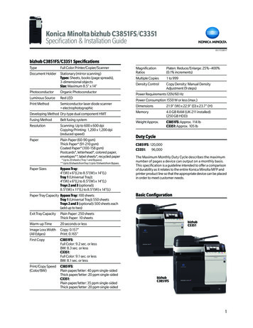
Touch RemoteFollow installation instructions for remote dial above.After power is applied to the system, operate as follows:1. Touch power button to turn fan on.Other Vari-Green controls, such as the ConstantPressure and Air Quality families of controls, have theirown manual that ship with the controller. They can alsobe found on Greenheck.com. See table on page 11 fordocument numbers.2. Touch UP/DOWN arrow to increase/decrease speed.3. Subsequent touches of the power button will startthe countdown timer of 90, 60, 30 or 10 minutes.CAUTIONEven though the motor may not be operating, highvoltage power may still be present at the motor. Makesure to disconnect power to the fan before servicing.4. LED's will turn off after a period of inactivity.5. To lock/unlock buttons, hold the UP and DOWNarrows for 3 seconds. When locked, the powerbutton will light up red.Remote Dial/Touch Remote AssemblyRemote Dial/Touch Remote Assembly100 ft. or or*NOTE: Black wire notused on some motorsGreen indiator light—Power presentTrip Point 1.85VDCContact Rating:10A @ 24-240VAC5A @ 30VDCREMOTE DIAL/TOUCH REMOTETRANSFORMERLow voltage, route awayfrom high voltage linesand/or use shielded cable2x4JunctionBoxFactory WiringField Wiring115/230 VAC inputto match motor name plateTroubleshooting Remote Dial/Touch RemoteRemote Dial with Min/Max SettingRemote Dial does not adjust motor RPM1. Check voltage to ensure the motor and transformerare receiving the correct line voltage.Upper Limit ButtonLower Limit Button2. Check voltage at the remote dial. 24 VDC should bepresent across the 24V and COM terminals. 0-10 VDCshould be present across the 0-10V and COMterminals.3. Verify all of the connections at the transformer andmake certain that they are secure.4. Touch remote: Verify that the touch remote is unlocked.LED Indicator5. To reset to default (0-10v) limits, hold both Upper andLower limit buttons down simultaneously until the LEDindicator lights up. Then release buttons and defaultlevels will be restored.Terminals24V-COM0-10V-COM8Vari-Green Motor and ControlsDesired Voltage24 VDC Nominal0-10 VDC(varies with dial position)
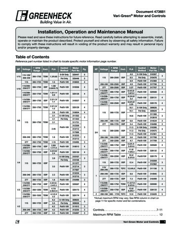
Two Speed Assembly115-230 VAC115-230 VACNEUTRALSPDTSwitch/Relayby othersFactory WiringField WiringLow voltage ( 10V), routeaway from high voltage linesand/or use shielded cable100' or lessRedBlack*WhiteFACTORY MOUNTED2 SPEED RALL2(115V-230V)L1(115V-230V)DigitalInputSpeed AAdjustmentGreen indicator light—Power presentSpeed BAdjustment*NOTE:Black wire not usedon some motorsDigital Input LogicL1 or L2 Speed BL1 and L2 Speed ANo input Off2x4JunctionBox115/230 VAC Inputto match motor nameplateTwo Speed ControlTroubleshooting - Two Speed ControlInstallation Overview: The two speed control is factorymounted to the fan and may be set to provide anytwo speeds the application requires. It also includes a24 VDC transformer. A green LED will be illuminatedwhen the 2-speed control is powered.1. Check all wiring connections to ensure they arecorrect and secure.1. There are two methods of toggling between speed Aand speed B:a. Dry contact input - this utilizes an externalswitching device such as a relay or SPDT switchto toggle between the two speeds. Connect terminal “A” to “COM” for speed A. Connect terminal “B” to “COM” for speed B.If no contact is made between either terminal themotor will be off.2. Verify AC line voltage is present at the motor and2-speed control.3. Verify 24 VDC is present at the 24V and COMterminals of the "Motor" terminal block.4. Measure DC voltage between the 0-10V and COMterminals of the "Motor" terminal block. This voltageshould match the dial position of the active dial.a. If using dry contact input - ensure contact closureis connecting the proper terminals.b. If using AC digital input - disconnect connectorfrom 2-speed control and measure voltagebetween L1 and Neutral or L2 and Neutral.b. AC digital input - this input allows an AC voltagesignal to be fed directly into the 2-speed controlto change speeds. Send 115-230V AC to L1 OR L2 for speed B. Send 115-230V AC to L1 AND L2 for speed A.If no voltage is applied to either terminal, themotor will be off.c. DO NOT CONNECT BOTH DRY CONTACT ANDDIGITAL INPUTS SIMULTANEOUSLY.2. To test fan operation before the external controldevices are installed, a jumper wire can beconnected between the COM and A or B terminal onthe dry contact input for fan operation. Vari-Green Motor and Controls9
Motorized BackdraftDamper ControlMotorized DamperMotorized damper operationwith Vari-Green Control(Motor/control wiring omitted for clarity)The available factory mounted transformer(PN 385253) has the ability to signal amotorized back draft damper to open/closeas the motor starts/stops.To controlTo motorA N.O./N.C. set of contacts is providedwhich will change state when above orbelow a control voltage of 1.85 VDC. Seewiring diagram for example.Contact Rating: 10A @ 24-240 VACN.C.COMN.O.COM24V0-10VCOM24V0-10V 5A @ 30 VDCAuxiliaryContactControlMotorTrip Point 1.85VDCContact Rating:10A @ 24-240VAC5A @ 30VDCGreen indicator light—Power presentFACTORY MOUNTEDTRANSFORMERNeutralLine(Damper Power Source)Fans Where Dial on Motoris Not AccessibleA control is available to mount on the outside of a fanwhere the dial on motor may be difficult to access(model SQ). This control is powered by the line voltageentering the fan and will send 24 VDC and 0-10 VDC tothe motor. Control Part Number is 385611Factory WiringField WiringFACTORY MOUNTEDSPEED CONTROLVoltagePresentInput: 85-265VACOutput: 24VDC, 0-10VDCCOM 24V 0-10V*NOTE: Black wire notused on some motorsRedBlack *White2x4JunctionBox115/230 VAC Inputto match motor name plate10Vari-Green Motor and Controls
Alternative: Fans Where Dial on Motor isNot AccessibleA control is available to mount on the outside of a fanwhere the dial on motor may be difficult to access(model SQ). In many cases, the tri-voltage platform ofVG motors can work off either 0-5V signal or a 0-10Vsignal. This control is powered by 5VDC output signalwire of the motor and will send a 0-5VDC to the motorto adjust the speed. Control PN 386512.ControlCompatible Motor P/N386512328447, 319356, 328128, 319357, 328129,318013, 328130, 320587, 320588, 328131,320589, 328132, 320590, 328133328173, 328174Factory WiringMaintenanceVari-Green motors use brushless technology withsealed bearings. No routine maintenance is requiredother than keeping any debris from accumulating on themotor and controls.Other Vari-Green ControlInstruction ManualsDescriptionDocument NumberIndoor Air Quality - VOC475407Indoor Air Quality Temperature/Humidity475573Constant Pressure Control474766Generation 2 ConstantPressure/Airflow Control479653Field WiringFACTORY MOUNTEDSPEED CONTROL54Input: 5VDC(Supplied Motor)Output: 0-5 VDC6372810109COM V-IN
The motor is pre-wired at the factory and cannot be changed inside the motor . Connect single-phase power at the voltage listed on the nameplate, along with the 0-10 VDC and 24V signal for speed control . NOTE: The motor will not operate without the proper control voltages . Operation and Wiring - 0-10V Input Only Operation and Wiring Dial on Motor