Transcription
Integrating the Virtual Switching System in CiscoData Center InfrastructureContentsIntroduction 2Audience 2Document Objective2Overview 2VSS Technology 3Key Concepts 4Virtual Switch Domain 4Virtual Switch Link (VSL) 5Multichassis EtherChannel (MEC) 5Cisco Data Center Architecture 6Integrated Services Model 7Services Chassis Model 7Cisco Data Center Architecture Leveraging VSSCore Layer 9Aggregation Layer 10Services Layer 11Access Layer 11Required Components 119VSS Design in the Aggregation Layer 12Infrastructure Description 12Core and Aggregation Layer Features 14Core Layer 14Aggregation Layer 16Corporate Headquarters:Cisco Systems, Inc., 170 West Tasman Drive, San Jose, CA 95134-1706 USACopyright 2009 Cisco Systems, Inc. All rights reserved.
IntroductionVSS Design in the Access Layer 36Infrastructure Description 36Traditional Aggregation Layer and VSS Access LayerVSS Aggregation and Access Layers 38Features 39Configuring Virtualization 39Layer 2 40Server Connectivity 40Conclusion3653Additional References53IntroductionThis document provides reference architectures and configuration guidance using the Cisco Catalyst6500’s Virtual Switching System (VSS) 1440 within an enterprise data center. The classic hierarchicalarchitectures presented in this guide position VSS technology and functionality at the aggregation andaccess layers of the data center network.AudienceThis document is intended for network engineers and architects who need to understand the designoptions and configurations necessary for the Cisco Catalyst 6500 virtual switching services in the datacenter network.Document ObjectiveThe objective of this document is to provide customers with guidance on how to deploy VSSfunctionality in a Cisco-based data center. This document is not intended to introduce the user to basicCisco data center design best practices, but rather to build on these well-documented concepts. Theprerequisite Cisco data center design knowledge can be found at the following locations: Cisco.com—Data Center:http://www.cisco.com/go/dc Cisco Validated Design (CVD) tworking solutions program home.htmlFor additional information regarding VSS and migration techniques, refer to the following: s/ps5718/ps9336/prod white paper0900aecd806ee2ed.htmlIntegrating the Virtual Switching System in Cisco Data Center Infrastructure2OL-18631-01
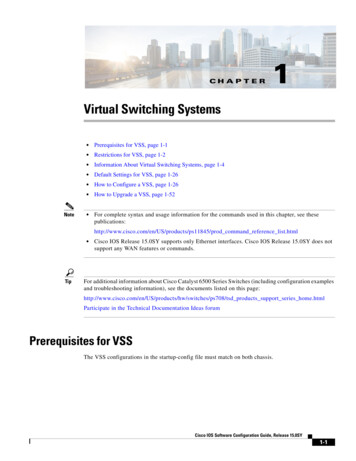
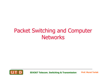
OverviewOverviewThe data center is a critical portion of the enterprise network. The data center network design mustaddress the high availability requirements of any device or link failure. It is also an area in which moreintelligence is required from the network in order to perform security and application services. Thisdocument describes the introduction of the Cisco Catalyst 6500 VSS in the enterprise data center design.In particular, this publication addresses the implementation of VSS technology at the access andaggregation layers of the data center and its effect on the availability of data center services andapplications.VSS TechnologyVSS technology allows for the grouping of two Cisco Catalyst 6500 switches into a single virtual switch.A VSS system provides physical infrastructure redundancy while simultaneously simplifying the logicaltopology of the data center.Figure 1 illustrates the concept of VSS. The left side of Figure 1 represents the physical layout of theVSS: two Cisco Catalyst 6500s are physically connected through a virtual switch link (VSL). The twoswitches are members of a virtual switch domain and, as the right side of the figure shows, this constructforms a single logical switch with a single control plane—a virtual switching system.Figure 1Virtual Switch SystemVirtual Switch SystemVirtual Switch SystemVirtualSwitch LinkNote225453Virtual Switch DomainThe VSS is sometimes referred to as the VSS1440, because it provides for 1.4 Tbps of forwardingswitching fabric.The primary benefits of this logical grouping include the following: Increased operational efficiency of a simplified network leveraging virtualization Increased availability and forwarding performance via Inter-chassis Stateful Switchover (SSO) andNonstop Forwarding (NSF) Increased availability and forwarding performance via Multichassis EtherChannel (MEC)The enterprise data center can leverage these VSS advantages. The remainder of this document willexplore the integration and impact of this technology on the data center and details how these benefitscan be achieved.Integrating the Virtual Switching System in Cisco Data Center InfrastructureOL-18631-013
OverviewNoteThis document focuses on the design aspects of VSS in a data center environment. For more informationon VSS technology, refer to the following dex.html hes/ps5718/ps9336/prod white paper0900aecd806ee2ed.htmlKey ConceptsThe following section describes the fundamental building blocks of the VSS functionality including: Virtual Switch Domain, page 4 Virtual Switch Link (VSL), page 5 Multichassis EtherChannel (MEC), page 5Virtual Switch DomainA Virtual Switch Domain consists of two Cisco Catalyst 6500s as members that meet the minimumsoftware and hardware requirements to obtain VSS functionality. See the “Required Components”section on page 11 for more details. The virtual switch domain is the boundary of the logical switchingsystem; each domain should be identified by a unique system ID. Currently, the Virtual Switch Domainmay consist of only two Cisco Catalyst 6500 platforms. Although the number of member switches islimited to two per domain, the number of domains is not; there are 255 unique domain IDs available.The VSS employs an active/standby control topology where the active VSS switch performs all controlplane functions. The following list highlights some of this control traffic: Layer 2—EtherChannel, Port Aggregation Protocol (PAgP), Link Aggregate Control Protocol(LACP), Spanning Tree Protocol (STP) Layer 3—Open Shortest Path First (OSPF), Enhanced Interior Gateway Protocol (Enhanced IGRP),Virtual Private Network (VPN) Routing and Forwarding (VRF), and so on First-hop Redundancy Protocols—Hot Standby Routing Protocol (HSRP), Virtual RouterRedundancy Protocol (VRRP), and so on Management Protocols—Simple Network Management Protocol (SNMP), Telnet, Secure Shell(SSH), and so onThe active virtual switch is chosen during the instantiation of the domain using the Role ResolutionProtocol (RRP) across the newly active VSL. In addition, the initialization of the domain requires thatall hardware and software requirements are met and configurations are synchronized between the virtualswitch domain members. These are all functions of the Virtual Switch Link Protocol (VSLP) that runsbetween the two domain members.When in a normal operating state, the VSS data plane is active/active and both switches in the domainare forwarding traffic. The inter-chassis Nonstop Forwarding/Stateful Switchover (NSF/SSO) allows thestandby switch to forward traffic. Each of the Policy Feature Cards (PFC) of the active and standbysupervisors performs forwarding decisions for traffic ingress to the their local switch ports. It should benoted that use of Distributed Forwarding Cards (DFC) features further enhances the forwardingcapabilities of the system.Integrating the Virtual Switching System in Cisco Data Center Infrastructure4OL-18631-01
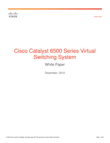
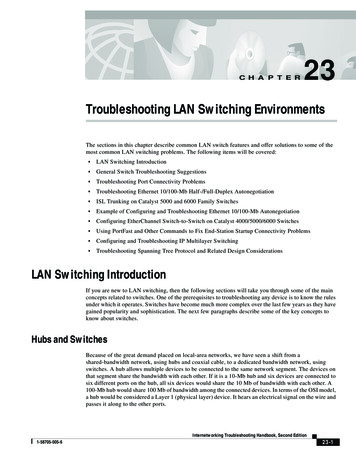
OverviewNoteVSS domain configuration details can be found in the “Core and Aggregation Layer Features” sectionon page 14 in the “VSS Design in the Aggregation Layer” section.Virtual Switch Link (VSL)As shown in Figure 1, the Virtual Switch Link (VSL) is an inter-switch link (ISL) that forms thebackbone of the VSS. The VSL supports control traffic between domain switches allowing the VSSsystem to form and operate. In addition, normal data traffic may also leverage the VSL connection as avalid forwarding path. The VSL link benefits from the high availability and scalability features of CiscoEtherChannel.The communication between VSS members across the VSL uses the Virtual Switch Link Protocol(VSLP). The VSLP includes the following protocols: Link Management Protocol (LMP) Role Resolution Protocol (RRP)LMP manages the VSL link providing for the exchange of domain member identities and switchparameters necessary to form the VSS. RPR validates the capabilities of the domain members andcoordinates the active switch election process. In addition to these functions, VSLP monitors the stateof the VSL connection via probe messages.All traffic traversing the VSL will have a 32-byte VSL header (VSH) inserted between the Ethernetpreamble and Layer-2 frame header. Each frame on the VSL is subject to predefined quality of service(QoS) rules that favor VSS control traffic to maintain system stability. The addition of the VSH to theEthernet frame requires ASIC support and thus the minimum VSS hardware requirements detailed in thesections that follow.Multichassis EtherChannel (MEC)EtherChannel allows multiple physical ports in a single switch to be aggregated forming one logical port.This logical port may be defined as a Layer-2 or Layer-3 interface consisting of a maximum of eightports. The ports comprising the EtherChannel interface are often spread across the line cards of amodular switch to provide a more resilient connection. In general, EtherChannel improves the overallscalability and availability of the network and is a well-documented best-practice within the data center.As Figure 2 illustrates, an EtherChannel may be defined between two switches or a server and switchingplatform.Switch and Server EtherChannel ExamplesSwitches usingEtherChannelServer usingEtherChannel225454Figure 2Integrating the Virtual Switching System in Cisco Data Center InfrastructureOL-18631-015
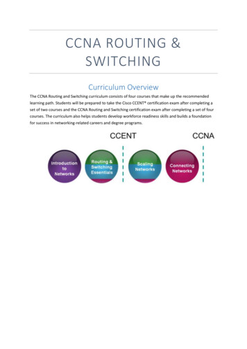
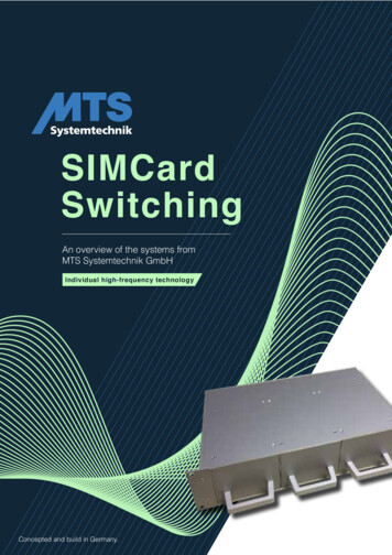
OverviewFigure 2 also exemplifies the one-to-one relationship that traditional EtherChannel entails. This is wherethe VSS system expands the realm of EtherChannel to create a one-to-many relationship using MEC.VSS allows an EtherChannel to exist across two physical chassis that are logically one. As shown inFigure 3, from a control plane perspective the VSS system is a single switch and thus the traditionalswitch may leverage EtherChannel. The right side of Figure 3 details that the EtherChannel is supportedacross two VSS-enabled chassis. This channel is forwarding on all ports; from a logical Layer-2perspective there is not loop. Convergence is no longer dependent on the implementation of spanningtree, but on the resilience of EtherChannel itself. The forwarding fabric is expanded and the Layer-2topology simplified.Figure 3VSS MEC Logical and Physical Switching TopologyVirtual Switch DomainVSSLogical ViewPhysical View225455MultichassisEtherChannelFigure 4 shows that the benefits of MEC are not limited to network switching devices, but extend to theserver farm. The left side of Figure 4 shows the logical topology. A single server aggregates ports to theVSS-enabled neighboring switch. This would appear to be a single point-of-failure until one reviews theright side of the slide representing the physical layout of VSS with MEC.Figure 4VSS MEC Logical and Physical Server TopologyVirtual Switch DomainVSSLogical ViewPhysical View225456MultichassisEtherChannelIn both switch and server configurations, a VSS-enabled switching layer enhances the availability andforwarding capabilities of traditional switch and server technologies. This benefit is transparentlyachieved through the currently available port aggregation techniques of these devices in combinationwith VSS MEC.Integrating the Virtual Switching System in Cisco Data Center Infrastructure6OL-18631-01
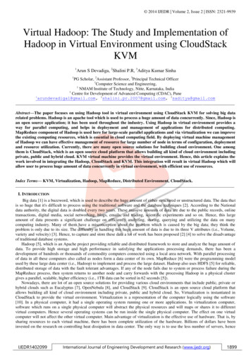
OverviewCisco Data Center ArchitectureThe following section reviews the current best-practice hierarchical data center designs. These designsform the foundation of the VSS-enabled data center architecture.Integrated Services ModelThe Cisco Catalyst 6500 platform offers the option of integrating service modules directly into card slotswithin the chassis, thereby conserving valuable rack space, power, and cabling in the data centernetwork. One common design model is to integrate these modules directly into the aggregation-layerswitches within the hierarchical network design, as shown in Figure 5. This approach is commonly takenwhen there are available slots within existing aggregation-layer switches, or chassis slot capacity isplanned and allocated to the service modules in the initial design.Figure 5Data Center Architecture—Integrated Services sAggregationData CenterServer Farm224595AccessServices Chassis ModelAs the data center network grows and needs to scale over time, there can be a requirement to recover theslots that are being consumed by the service modules in order to accommodate greater port density inthe aggregation layer. This would allow aggregation of a greater number of access-layer switcheswithout needing to move to a second aggregation block. Other factors might drive the migration awayfrom an integrated services approach, such as the desire to deploy new hardware in the aggregation layerthat may not support the Cisco Catalyst 6500 service modules. For example, the Cisco Nexus 7000 Seriesswitches have a different linecard form factor and do not support Cisco Catalyst 6500 service modules.Integrating the Virtual Switching System in Cisco Data Center InfrastructureOL-18631-017
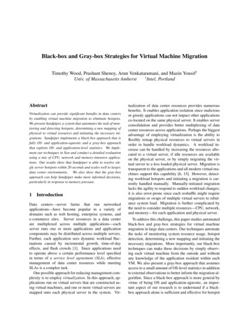
OverviewThe initial release of the Cisco Catalyst 6500 VSS 1440 does not support installation of service modulesbeyond the Network Analysis Module (NAM) in the chassis; this support requires new software that isplanned for Cisco IOS Release 12.2(33)SXI.Since these modules require a Cisco Catalyst 6500 chassis for power and network connectivity, anotherapproach for integrating these devices into the data center network may be considered. One approach isthe implementation of an additional pair of Cisco 6500 chassis that are adjacent to the aggregation layerof the data center network. These switches are commonly referred to as services chassis. Figure 6illustrates the physical topology of the services chassis data center design.Figure 6Data Center Architecture—External Services cesChassisServicesData CenterServer FarmNote224596AccessAt the time of writing Cisco IOS 12.2(33)SXI is not available. As a result, all of the testing has beenperformed leveraging the services chassis model to understand the behavior of VSS in combination withintelligent network services—specifically the Firewall Services Module (FSM) and Application ControlEngine (ACE) service module.For more information on services chassis design, see the following URL: se/Data Center/dc servchas/service-chassis design.htmlIntegrating the Virtual Switching System in Cisco Data Center Infrastructure8OL-18631-01
OverviewCisco Data Center Architecture Leveraging VSSThis section discusses where VSS might prove beneficial in the enterprise data center. Figure 7 depictsthe location of VSS-enabled switches in the tested enterprise data center topology.Figure 7Test Bed ta CenterServer FarmNote225457AccessMEC is leveraged between all entities and the VSS-enabled devices; although it is not a requirement, itis a best practice.Core LayerThe data center core is traditionally a high-speed, Layer-3 fabric leveraging routing protocols forreliability and rapid convergence. The core employs Equal Cost Multi Path (ECMP) allowing thedistribution of load across the data center infrastructure. The data center core at a minimum employsGigabit Ethernet, but predominately consists of 10 Gigabit Ethernet connections.Integrating the Virtual Switching System in Cisco Data Center InfrastructureOL-18631-019
OverviewWhen considering the use of VSS at any layer of the data center, you must consider the advantages thatVSS provides versus the role you asks it to play. For example, VSS allows you to reduce the complexityof the data center via virtualization. Thus, if you employ VSS at the core, the number of routing instancesgoes from two distinct devices to one logical entity. This may seem an insignificant reason to migrate toVSS at the core layer, but most benefits of VSS occur at Layer 2.It is important to remember that current Enhanced IGRP or OSPF deployments in the core of the datacenter provide a very robust Layer-3 environment that is well-maintained and understood by networkadministrators. There is little motivation to move away from the traditional core model to VSS forsimplicity, manageability, or availability reasons. Therefore, VSS was not enabled at the core layer ofthe data center for test effort associated with this publication; however, the advantages of VSS at theneighboring aggregation-layer switches is observable at the core with rapid predictable convergencetimes.NoteThere is a growing trend in the data center to support increasingly larger Layer-2 domains for flexibleserver and application environments. This is a problem VSS can address; however, at this time it isprobably best to contain these VLANs within a Layer-3 boundary at the aggregation layer. ExtendingVLANs through the core is not a best practice at this time and should only be considered an exceptionto a long existing rule.Aggregation LayerThe aggregation layer of the data center provides connectivity for the access-layer switches in the serverfarm and aggregates them into a smaller number of interfaces to be connected into the core layer. In mostdata center environments, the aggregation layer is the transition point between the purely Layer-3 routedcore layer and the Layer-2 switched access layer. 802.1Q trunks extend the server farm VLANs betweenaccess and aggregation layers.As shown in Figure 7, the aggregation layer also provides a common connection point to insert servicesinto the data flows between clients and servers, or between tiers of servers in a multi-tier application.The services chassis are dual-homed into the aggregation layer with 802.1Q trunks similar to the waythat access-layer switches are connected.The aggregation layer is an ideal location to introduce VSS. VSS logically creates a single logical switchfrom two physical switches. The Services Switches are logically homed to a single aggregation layerswitch, but physically dual-homed to the VSS-enabled switches using MEC. Redundant physical pathsare maintained while removing the dependence on redundancy protocols such as STP and FHRP. VSSsimplifies the Layer-2 and Layer-3 topology of the data center.NoteIt is always recommended to enable spanning tree when redundant physical paths exist in the network.It must be understood that, in a VSS environment, the services of spanning tree are not leveraged—butshould be enabled.Figure 7 highlights another best practice when leveraging VSS: Dual-homing of all devices to the VSS,including access, service and core switches. Dual-homing allows the use of MEC throughout the datacenter, allowing traffic to flow optimally within the data center and to converge at the port level.Orphaned, or single-homed devices, force traffic over the VSL link between VSS switches. This ispossible, but proper VSL capacity planning must be taken into account. The VSL link may be comprisedof up to eight physical 10 Gigabit Ethernet links. This would appear more than ample, but determiningthe requirements for the applications residing in each data enter must be taken. Single-homed devicesIntegrating the Virtual Switching System in Cisco Data Center Infrastructure10OL-18631-01
Overviewmight become “isolated” from the network if the VSS aggregation-layer switch it leverages fails. It is abest practice to physically dual-home all devices to a VSS environment, avoiding the potential of deviceisolation.Services LayerThe services layer employs intelligent integrated service modules. At the time of testing, the VSS systemofficially supported one service module—the Network Analysis Module (NAM). This current productlimitation prevents the use of the Application Control Engine (ACE) and Firewall Services Modules(FWSM) from the services-layer test environment. These application and security services areconsidered critical for today’s enterprise data center and therefore preclude the use of VSS at the serviceslayer. The services layer referenced in this document does not employ VSS, but does benefit from theuse of VSS at the aggregation layer of the data center.For more information on services chassis design please go to the following URL: se/Data Center/dc servchas/service-chassis design.htmlAccess LayerThe access layer of the data center provides entry to the compute power of the data center, namely theserver farms. The access layer offers port density, availability and scalability to end nodes. It alsopresents an opportunity for network administrators to leverage VSS technology—making the most of thehighly available and robust forwarding fabric VSS provides. A VSS access layer permits: Full forwarding fabric via MEC uplinks to the aggregation layer Simplified Layer-2 topology via VSS virtualization Full forwarding fabric to servers leveraging MEC enabled edge portsThe remainder of this document focuses on the implementation of VSS in the enterprise datacenter—specifically the aggregation and access layers. It details the changes required in the neighboringnetwork layer devices to realize the advantages of VSS in the data center.Required ComponentsThe hardware and software components listed in Table 1 were used in the construction of the validateddesign models addressed in this publication.Table 1Hardware and Software ComponentsDesign ComponentsPlatforms, Line Cards, End Points within RoleReleasesCore Router/SwitchCisco Catalyst 6500 0-10GIntegrating the Virtual Switching System in Cisco Data Center InfrastructureOL-18631-0111
VSS Design in the Aggregation LayerTable 1Hardware and Software Components (continued)Aggregation Router /SwitchCisco Catalyst 6500 04-10GEWS-X6708-10GEServices Layer SwitchWS-SVC-NAM-23.6(1a)Cisco Catalyst 6500 Series12.2(33)SXH2aVS-S720-10GWS-X6704-10GEAccess Layer 500-K9A2(1.1)Cisco Catalyst 6500 8-GE-TXServer EnvironmentsWS-SVC-NAM-23.6(1a)HP ProLiant DL580 G4Windows 2003 SP2Red Hat enterpriseLinux Server release5.2 (Tikanga)VMware ESX Server,3.0.3, 104629VSS Design in the Aggregation LayerThis section addresses VSS design in the aggregation layer by presenting the following sections: Infrastructure Description, page 12 Core and Aggregation Layer Features, page 14Infrastructure DescriptionFigure 7 on page 9 illustrates the physical implementation of the tested VSS data center topology. Theenvironment consists of Cisco Catalyst 6500 switching platforms connected via 10 Gigabit Ethernetlinks. From a physical perspective, this is consistent with the hierarchical data center designs in usetoday. However, appearances can be deceiving because a VSS-enabled data center introduces a logicallystreamlined data center environment. Figure 8 is a view of the VSS-enabled data center. As Figure 8shows, VSS simplifies the aggregation layer by replacing multiple devices with a single VSS identity.Integrating the Virtual Switching System in Cisco Data Center Infrastructure12OL-18631-01
VSS Design in the Aggregation LayerFigure 8VSS Logical Test TopologyCore.1.210.7.0.x/24Aggregation.110 Po.7 11.1.x/24.1.212 24Po 2.x/.7.10Po21222Po2Po52- 46Po51Po31Services16 Access Switches225458AccessThe aggregation layer of the data center is typically defined as the dividing line between Layer-2 andLayer-3 services—being both a routing entity and the primary root for most (if not all) VLANs in thedata center. VSS can simplify this deployment.At the aggregation layer, VSS allows the use of MEC between itself and all neighboring devices. Asshown in Figure 8, a Layer-3 MEC, port channel, exists between the core and aggregation layers of thedata center, thereby simplifying routes into and out of the data center. Perhaps more significant is theremoval of logically redundant paths in the data center. There are no Layer-2 loops with which tocontend—mitigating the reliance on spanning tree for path resolution. All links are forwarding,non-blocking from a spanning tree perspective. The advantages of using VSS at the aggregation layerextend to the Layer-2 devices it supports at the access and services layers.Integrating the Virtual Switching System in Cisco Data Center InfrastructureOL-18631-0113
VSS Design in the Aggregation LayerCore and Aggregation Layer FeaturesCore LayerOverviewThe core layer consists of two Cisco Catalyst 6500s leveraging Sup720’s with 10 Gigabit Ethernet. Thecore is defined strictly as a Layer-3 domain that is NSF aware. The VSS at the aggregation layerleverages interchassis NSF/SSO, allowing the standby VSS switch to assume control planeresponsibilities in the event of the active VSS switch failing. NSF allows for traffic forwarding withoutrequiring the routing topology to converge.Figure 9 illustrates the Layer-3 configuration between the core routers and the VSS aggregation router;an Interior Gateway Protocol (IGP) mediates the Layer-3 relationship between tiers. Notice that there isa single routing instance defined at the aggregation layer—the VSS-enabled layer. Layer-3 port channelsuse MEC to connect the core and aggregation routers.Using MEC and NSF between the routing devices provides for physical path redundancy withoutrequiring a routing topology convergence when the MEC links are failed or recovered. The objective ofNSF is to maintain the flow of traffic over a defined, pre-existing routing topology. MEC complementsthis capability by providing physical path redundancy, obscuring failure events from the routingprotocol. The traffic continues to flow in the event of a link or VSS member failure because of thecombined benefits of MEC and NSF. The introduction of VSS at the aggregation layer mitigates theimpact of routing topology changes at the core by fundamentally eliminating them.Layer-3 Topology at the Core and Aggregation VSS MSFC10 P.7 o1.2 1.x/24.2.1.212 /24Po .2.x.710dca-vss225459Figure 9As the combined use of NSF and MEC dampens Layer-3 routing changes, network administrators shouldnot implement aggressive IGP timers—namely HELLO and HOLD-TIME timers. The objective of thesetimers is to detect and act upon state changes of routing neighbors to maintain valid routes. This is theopposite goal of NSF. We currently recommend maintaining default IGP timers in a VSS-enabledenvironment, allowing NSF/SSO and MEC to provide a stable Layer-3 environment. Testing of variousfailures between the core and aggregation layers with default IGP timers resulted in near zero failovertimes.NoteOSPF, Enhanced IGRP, Border Gateway Protocol (BGP) and Intermediate System-to-IntermediateSystem (IS-IS) are NSF-aware protocols.Integrating the Virtual Switching System in Cisco Data Center Infrastructure14OL-18631-01
VSS Design in the Aggregation LayerFeaturesThe following section describes the configuration of the core switches when neighboring with aVSS-enabled aggregation layer.Enhanced IGRP ConfigurationThe use of MEC requires creation of a logical port, or port channel, to represent the aggregated ports onthe platform. The port channel may be created leveraging either a statically or dynamically leveraging alink aggregation protocol such as LACP or PAgP.In the following example based on Figure 9, two 10 Gigabit Ethernet ports are logically combined toform port channel “11” on dca-core1. This port channel uses PAgP to negotiate membership across twoVSS member switches. The use of PAgP “desirable” mode means that the interface will be activelyseeking membership in a channel.interface TenGigabitEthernet4/1description to VSS Switch 1 no ip addresschannel-protocol pagpchannel-group 11 mode desirable!interface TenGigabitEthernet4/2description to VSS Switch 2 no ip addresschannel-protocol pagpchannel-group 11 mode desirable!The port channel interface is dynamically created when declared on the first physical interfaceconfigured as a member. At this point it is a Layer-2 interface until an IP address has been associatedwith it. Below port channel “11” is defined as a Layer-3 interface participating in Enhanced IGRP.NoteThe use of PAgP is not required, but is desirable if you intend to use Enhanced PAgP to be leveraged asa dual-active detection mechanism for VSS. See the Aggregation Layer, page 16 for more details.interface Port-channel11description ** to VSS ** ip address 10.7.1.1 255.255.255.0ip authentication mode eigrp 7 md5ip authentication key-chain eigrp 7 eigrp!The Enhanced IGRP routing instance on the dca-core1 router has the following configuration:router eigrp 7network 10.0.0.0no auto-summaryeigrp router-id 1.1.1.1nsf!NoteThere are no custom timers in the configuration and that the router is NSF aware.OSPF ConfigurationThe use of MEC to the core layer allows simplification of the Layer-3 infrastructure. Dynamic PAgP orLACP aggregation allows for individual links in the MEC to fail without requiring a routing topologychange; therefore, the timers are set to their defaults to dampen their on the network. Allowing theresiliency of NSF/SSO and MEC to provide a highly available Layer-3 environment.Integrating the Virtual Switching System in Cisco Data Center InfrastructureOL-18631-0115
VSS Design in the Aggregation LayerThe following configuratio
document describes the introduction of the Cisco Cataly st 6500 VSS in the enterprise data center design. In particular, this publication addresses the implementation of VSS technology at the access and aggregation layers of the data center and its effect on the availability of data center services and applications. VSS Technology