Transcription
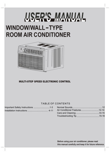
USE & CARE GUIDE618,500 -25,000 BTUWindow Heat / Cooling UnitCAMHE18C2 CAMHE25C2Customer Focused. Quality Driven.TMwww.crosley.com
TABLE OF CONTENTSImportant Safety Instructions .1-3Installation Instructions . 4-11Normal Sounds .12Air Conditioner Features .12-14Care and Cleaning .14-15Troubleshooting .15-16Before using your air conditioner, please readthis manual carefully and keep it for future reference.
IMPORTANT SAFETY INSTRUCTIONSREAD THIS MANUALInside you will find many helpful hints on how to use and maintain your air conditionerproperly. Just a little preventive care on your part can save you a great deal of timeand money over the life of your air conditioner. You'll find many answers to commonproblems in the chart of troubleshooting tips. If you review our chart of TroubleshootingTips first, you may not need to call for service at all.To prevent injury to the user or other people and property damage, the followinginstructions must be followed. Incorrect operation due to ignoring of instructions maycause harm or damage. The seriousness is classified by the following indications.WARNING This symbol indicates the possibility of death or serious injury.CAUTION This symbol indicates the possibility of injury or damage to property.Always do this.Never do this.WARNING!!!!!!Plug in power plugproperly.Do not operate or stop theunit by inserting or pullingout the power plug.Do not damage or use an unspecified powercord.Otherwise, it may cause electricshock or fire due to excess heatgeneration.It may cause electric shock or firedue to heat generation.It may cause electric shock or fire.If the power cord is damaged, it must be replaced by themanufacturer or an authorised service centre or a similarlyqualified per son in order to avoid a hazard.Always install circuitbreaker and a dedicatedpower circuit.Do not operate with wethands or in dampenvironment.Do not direct airflow at room occupants only.Incorrect installation may causefire and electric shock.It may cause electric shock.This could damage your health.Always ensure effectivegrounding.Do not allow water to runinto electric parts.!Incorrect grounding may causeelectric shock.It may cause failure of machineor electric shock.It may cause electric shock or fire due to heat generation.Unplug the unit if strangesounds, smell, or smokecomes from it.Do not use the socket if it isloose or damaged.It may cause fire and electricshock.It may cause fire and electricshock.Keep firearms away.Do not use the power cordclose to heating appliances.It may cause fire.It may cause fire and electricshock.Ventilate room before operating air conditioner if there isa gas leakage from another appliance.Do not modify power cord length or share theoutlet with other appliances.Do not open the unit during operation.It may cause electric shock.Do not use the power cord near flammable gasor combustibles, such as gasoline, benzene,thinner, etc.It may cause an explosion or fire.Do not disassemble or modify unit.It may cause failure and electric shock.It may cause explosion, fire and, burns.1
IMPORTANT SAFETY INSTRUCTIONSCAUTION!When the air filter is to beremoved, do not touch the metalparts of the unit.It may cause an injury.Do not put a pet or house plantwhere it will be exposed to directair flow.This could injure the pet or plant.Do not use strong detergentsuch as wax or thinner but usea soft cloth.Appearance may be deteriorateddue to change of product color orscratching of its surface.Do not clean the air conditionerwith water.Stop operation and close thewindow in storm or hurricane.Water may enter the unit anddegrade the insulation. It maycause an electric shock.!Operation with windows openedmay cause wetting of indoor andsoaking of household furniture.!Always insert the filters securely.Clean filter once every two weeks.Operation without filters maycausefailure.Do not place obstacles aroundair-inlets or inside of air-outlet.!!An oxygen shortage may occur.Do not use for special purposes.Do not use this air conditioner topreserve precision devices, food,pets, plants, and art objects.It maycause deterioration of quality, etc.When the unit is to be cleaned,switch off, and turn off the circuitbreaker.Do not clean unit when power is onas it may cause fire and electric shock,it may cause an injury.!!Hold the plug by the head of thepower plug when taking it out.!It may cause electric shock anddamage.Do not place heavy object on the powercord and ensure that the cord is notcompressed.Ventilate the room well whenused together with a stove, etc.Ensure that the installation bracket of theoutdoor appliance is not damaged dueto prolonged exposure.If bracket is damaged, there isconcern of damage due to fallingof unit.Turn off the main powerswitch when not using theunit for a long time.It may cause failure of product orfire.Do not drink water drainedfrom air conditioner.It contains contaminants andIt may cause failure of applianceThere is danger of fire or electriccould make you sick.or accident.shock.! Use caution when unpacking and! If water enters the unit, turn the unit off at the poweroutlet and switch off the circuit breaker. Isolateinstalling. Sharp edges could cause injury.supply by taking the power-plug out and contact aqualified service technician.CAUTIONThe appliance shall be installed in accordancewith national wiring regulations.Do not operate your air conditioner in a wet roomsuch as a bathroom or laundry room.The appliance with electric heater shall have atleast 1 meter space to th e combustible materials.Contact the authorised service technician forrepair or maintenance of this unit.Contact the authorised installer for installationof this unit.This appliance is not intended for use by persons(including children) with reduced physical ,sensoryor mental capabilities or lack of experience andknowledge, unless they haveb eengi vensu pervisionor instruction concerning use of the appliance bya person responsible for their safety.Children should be supervised to ensure that theydo not play with the appliance.If the supply cord is damaged, it must be replacedby the manufacturer, its service agent or similarlyqualified persons in order to avoid a hazard.2
IMPORTANT SAFETY INSTRUCTIONSWARNINGNOTE:The power supply cord with this airconditioner contains a current detectiondevice designed to reduce the risk of fire.Please refer to the section Operationof Current Device for details.In the eventthat the power supply cord is damaged,it cannot be repaired-it must be replacedwith ac ordf romt heP roductM anufacturer.WARNINGAvoid fire hazard or electric shock. Do notuse an extension cord or an adaptor plug.Do not remove any prong from the powercord.Grounding type wallreceptacleDo not, under anycircumstances, cut,remove, or bypassthe grounding prong.Power supply cordwith 3-prong grounding plugand current detection deviceFor Your SafetyDo not store or use gasoline or other flammable vapors and liquids in the vicinityof this or any other appliance.WARNINGPrevent AccidentsTo reduce the risk of fire, electrical shock, or injury to persons when using yourair conditioner, follow basic precautions, including the following:Be sure the electrical service is adequate for the model you have chosen. Thisinformation can be found on the serial plate, which is located on the side of thethe cabinet and behind the grille.If the air conditioneri s to be installed in a w indow, you will probably want to cleanboth sides of the glass first.I f the windowis a triple-track type with a screen panelincluded, remove the screen completely before installation.Be sure the air conditionerh as been securely and correctly installed according tothe installation instructions in this manual. Save this manual for possible futureuse in removing or installing this unit.When handling the air conditioner, be careful to avoid cuts f rom sharp metal f inson front and rear coils.WARNINGElectrical InformationThe complete electical rating of your new room air conditioner is stated on theserial plate. Refer to the rating when checking the electrical requirements.Be sure the air conditioner is properly grounded. To minimize shock and firehazards, proper grounding is important. The power cord is equipped with athree-prong grounding plug for protection against shock hazards.Your air conditioner must be used in a properly grounded wall receptacle. If thewall receptacle you intend to use is not adequately grounded or protected by atime delay fuse or circuit breaker, have a qualified electrician install the properreceptacle. Ensure the receptacle is accessible after the unit installation.Do not run air conditioner without side protective cover in place.This couldresult in mechanical damage within the air conditioner.Do not use an extension cord or an adapter plug.Operation of Current DeviceNOTE:(Applicable to the unit adopts current detectiondevice only )The power supply cord contains a current device that sensesdamage to the power cord. To test your power supply cord dothe following:1. Plug in the Air Conditioner.2. The power supply cord will have TWO buttons on the plughead. Press the TEST button, you will notice a click as theRESET button pops out.3. Press the RESET button, again you will notice a click asthe button engages.4. The power supply cord is now supplying electricity to theunit. (On some products this it also indicated by a light onthe plug head.)Do not use this device to turn the unit on or off.Always make sure the RESET button is pushed in forcorrect operation.The power supply must be replaced if it fails reset wheneither the TEST button is pushed, or it cannot be reset. Anew one can be obtained from the product manufacturer.If power supply cord is damaged, it cannot be repaired. ItMUST be replaced by one obtained from the productmanufacturer.NOTE:This air conditioner is designed to be operatedunder condition as follows:Cooling Outdoor temp:operation Indoor temp:64-109OF/18-43OC (64-125OF/18-52OCfor special tropical models)OO62-90 F/17-32 C23-76OF/-5-24 CHeating Outdoor temp:Ooperation Indoor temp:32-80 F/0-27 CNote: Performance may be reduced outside of theseoperating temperatures.OO3
INSTALLATION INSTRUCTIONSPreliminary InstructionsBEFORE YOU BEGINRead these instructions completelyand carefully.IMPORTANT- Save theseinstructions for local inspector s use.IMPORTANT- Observe allgoverning codes and ordianaces.Note to Installer- Be sure to leave theseinstructions with the Consumer.Note to Consumer- Keep theseinstructions for futrue reference.Skill level- Installatio of this appliancerequires basic mechanical skills.Completion time- Approximately 1 hour.We recommend that two people installthis product.Proper installation is the responsibilityof the installer.Product failure due to improper installationis not covered under the Warranty.You MUST use all supplied parts and useproper installation procedures as describedin these instructions when installing this airconditioner.Window Sash SealSafety Lock and3 /4 (or1/2 ) LongHex Head ScrewTop AngleFoam GasketWasher HeadLocking screwFrameAssembly(Left)Side RetainerBottom railseal to Unit1 /2 LongScrew andLocknutsLocknut3 /4 LongFlat HeadBoltFrameAssembly(Right)Window SupportBracketSill AngleBracketDo the following before starting to install unit.See illustrations below.Check dimensions of your unit to determinemodel type:Unit Height:18 5/817 5/8Unit Width:261/2235/81Min. Window Opening:19 /2181/23128Min. Window Width:42401/2Max. Window Width:CAUTIONFig.EFig.DDo not, under any circumstances, cut orremove the third (ground) prong from thepower cord.SASHSASH19 MIN.19 MIN.Do not change the plug on the power cordof the air conditioner.Aluminum house wiring may present specialproblems- consult a qualified electircian.1/2 MIN.When handling unit, be careful to avoid cuts fromsharp metal edges and aluminum fins on front andrear coils.Storm Window Frame orOther Obstruction1/2 MIN.Storm WindowFrame or OtherObstruction1/2 MIN.BoardThicknessAs Required,Along EntireStool. FastenWith Two NailsOr Screws.1. Check window opening size-- the mountingparts furnished with this air conditioner aremade to install in a wooden sill double-hungwindow. The standard parts are for windowdimensions listed above. Open sash to a minimum of 19 inches(483mm). See Fig.D.2.Check condition of window-- all wood parts ofwindow must be in good shape and able to firmlyhold the needed screws. If not, make repairsbefore installing unit.NOTE:Save Carton and these Installation Instructionsfor future reference. The carton is the best wayto store unit during winter, or when not in use.4
INSTALLATION INSTRUCTIONSA.Window MountingPreliminary Instructions1 Remove Chassis3. Check your storm windows-- if your stormwindow frame does not allow the clearancerequired, correct by adding a piece of wood asshown in Fig. E,or by removing storm windowwhile room air conditioner is being installed.4 .Check for anything that could block airflow-check area outside of window for things such asshrubs, trees, or awnings. Inside, be surefurniture, drapes, or blinds will not stop properairflow.5.Check the available electrical service- Powersupply must be the same as that shown on theunit serial nameplate. Power cord is 48 incheslong. Be sure you have an outlet near.6.Carefully unpack air conditioner- Remove allpacking material. Protect floor or carpet fromdamage. Two people should be used to moveand install unit.1. Pull down front grille and remove filter.(See Fig.1).2. Lift front grille upwards and place to one side.3. Locate the four front screws and remove.These screws will be needed to re-installthe front panel (see Fig.2).Front PanelFront GrilleFig.14. Push metal cabinet side to release plastic tabson each side of front panel (see Fig.3).5. Gently lift front panel off unit(see Fig.3A).6. Disconnect the connector plug of the displaypanel from the unit and place front panel to oneside(see Fig.4).Hardware(Packed with the unit)7/16 inch Lockingscrew and Flatwasher for windowpanels2 ea.3 / 4 or 1/2)inchLong Hex-headScrew7Safety Lock1Fig.2Fig.31 / 2 inch Longscrew and Locknut4ea.3 / 4 inch LongFlat Head Boltand Locknut2ea.Sill AngleBracketLong hex-headlocking screwfor top angle,side retainer5 /16 inch LongFig.3A22Window sashseal foam1R1 hardware2(10 *3/4 *1/12 )7. Remove shipping screws from top of unit andalso on the side by the base if installed(see Fig.5).8. Hold the cabinet while pulling on the base panhandle, and carefully remove the unit.9. Add two foam inserts to holes in top of cabinetwhere shipping screws were removed from(see Fig.6).shippingscrews10Foam insertWeather strippingFig.45NOET: R1 hardware and Weather stripping is onlyfor Energy star models.Tools RequiredA large flat blade screwdriver;Tape measureAdjustable wrench or pliers;Pencil;LevelSocket wrenches;Phillips ScrewdriverFig.55Fig.6
INSTALLATION INSTRUCTIONS10. Your unit may come with internal packaging.This packaging must be removed prior toinstalling the air conditioner back into thecabinet.(see Fig.7).TopViewAir ConditionerCabinetShipping Packaging"" SectionFig.10Plastic tiePlasticFrameLockingScrewWindow HoleFillerPanel3. Insert top and bottom legs of windowfiller panel frame into channel in thetop angle and bottom rail. Do bothsides.4. Insert washer head locking 7/16" screws(2) into holes in top leg of filler panelframe (see step 6). Do not totally tighten. Allow leg to slide freely. Screwswill be tightened after section 6.Fig.72 Install Top Angle andSide Bracket1. Attach foam gasket to top angleabove holes as shown in Fig.6.2. Install top angle and side retainersto cabinet as shown in Fig.8 (10 screws).4Place Cabinet in1.Open window and mark center of window stool asshown(Fig.11).2. Place cabinet in window with bottom stool anglefirmly seated over window stool as shown. Bringwindow down temporarily behind top angle tohold cabinet in place(Fig.12).5 /1he 6 lox-h ngeadFig.83 Assemble Window Filler Panels1. Place cabinet on floor, a bench, ora table.,, ,,2. Slide I section of window filler panelinto side retainer on the side of thecabinet (see Fig.9 & Fig.10).Do both sides.PlasticFrameFig.11Window FillerPanelStoolStoolAngleFig.123. Shift cabinet left or right as needed to line upcenter of cabinet on center line marked on stool.4. Fasten cabinet to window stool with 2 screwsinto holes(You may wish to pre-drill pilot holes).5. Add bottom rail seal over screws to window stool.Side RetainerFig.96
INSTALLATION INSTRUCTIONS1 2 Long ScrewsAnd LocknutsLeftBottomRail SealLocknutSill AngleBracket3 4 (or1/2 )LongHex-head ScrewRightFlat HeadBolt2 Each Required ForEach Support BracketFig.135 Install Support BracketFig.15B1. Hold each support bracket flush againstoutside of sill, and tight to bottom of cabinetas shown in Fig.15A. Mark brackets at top levelof sill, and remove.2. Assemble sill angle bracket to supportbrackets at the marked position(Fig.15B).Hand tighten, but allow for any changes later.3. Install support brackets(with sill anglebrackets attached) to correct hole inbottom of cabinet as shown in Fig.16.4. Tighten all 6 bolts securely.NOTE: Check that air conditioner is tilted back about1 1/ 4 to 1 5/ 8 (tilted about 3 O t o 4 O downward to th e o utside).After proper installation, condensate should not drainfrom the overflow drain h ole d uringn ormalu se,c orrectthe slope otherwise (Fig.14).FIG.14Measure fromthe cabinet edge.Window Sash1 2 Long Screwsand LocknutsAbout1 1/ 4 to1 5/ 85Fig.166 Extend Window Filler Panels1. Carefully raise window to expose filler panellocking screws. Loosen screws so filler panelsslide easily.2. Extend panels to fill window opening completely.Tighten locking screws on top(Fig.17).3. Close window behind top angle.Side LouversSill Angle BracketWindow SillL o c k ing Screw7/16"Locking Screwand WasherMarkFig.17Fig.15A7
INSTALLATION INSTRUCTIONS4. Attach the top angle to window frame: Use a 3/32drill bit to drill one hole through the hole in themiddle of top angle into the window frame, anddrive one 3/ 4 (or 1/ 2 ) HEX-HEAD locking screwthrough hole in the middle of top angle into thewindow frame as shown (Fig.17A).8 Install Window Sash Seal andSafety Lock1. Trim sash seal to fit window width. Insert intospace between upper and lower sashes(Fig.18).Fig.17AWindow Sash Seal3/ 4 (or 1/ 2 ) longHEX-HEADSCREWFig.182. Attach right angle safety lock (Fig.19).Safety Lock7 Attach Window Filler Panels toWindow Frame3 4 (or1 /2 )LongHex-head Screws1. Extend the window filler panels out against thewindow frame.2. Use a 1/8" drill bit to drill a starter hole through thehole in the top leg of each window filler panel andinto the window sash (Fig. 18A and Fig. 18B).Connect with one 3/ 4 (or 1/ 2") long hex headscrew.Fig.199 Install Chassis into Cabinetand Install Front to UnitFig.18A1. Lift air conditioner and carefully slide intocabinet leaving 6 inches protruding.2. DO NOT push on controls or finned coils.3. Be sure chassis is firmly seated towards rearof cabinet.4. Installation of front is the reverse of removaloutlined in Section 1.A.3/ 4 (or 1/2 ) long hex head screwB. Left-hand Window FillerPanel Top LegC. Window channel10Fig.18BINSTALL R1 HARDWARE (only beapplicable to Energy star models )In order to minimize air leaks and ensure optimalinsulation, it is necessary to install the included R1hardware to the side curtain. Follow the instructionsbelow.Step 1. After the unit is installed to the window,measure the inner width of the side curtain as shown(Fig.20).Step 2. Remark a line on the provide R1 insulationpanel according to a length 1/8 (3mm) less than themeasured width in step 1, then cut the R1 insulationpanel along the line (Fig.12).A.3/ 4 (or1/2 ) long hex head screw8
INSTALLATION INSTRUCTIONS11INSTALL WEATHER STRIPPING (onlybe applicable to Energy star models )In order to minimize air leaks between the room airconditoner and the window opening, trim the weathersttipping with a proper length, peel off the protectivebacking and plug any gaps if needed (Fig.23).1122345367489105111261314151617Measure the inner widthof the side curtainFig.20Fig.23orFig.21Step 3. Slide the R1 insulation panel into the sidecurtain, the side with pattern should facing the indoorside.(Fig.22).Fig.22Step 4. Repeat on the other side.9
INSTALLATION INSTRUCTIONSB.Thru-The-Wall InstallationInside Frame Height: 18-7/8"(47.9cm) or18" (45.7cm)Inside Frame Width: 26-3/4"(67.9cm) or 23-7/8"(60.6cm)NOTE: Consult local building codes prior toinstallation, or a qualified carpenter.1 Select Wall LocationYThe air conditioner has a slide-out chassis, sothat it can be installed through an outside wallas specified below:Max. Wall thickness: 12or10IMPORTANT: Side louvers must never be blocked.NOTE: All parts needed for Thru-The-Wall Installtion are provided, except a wood frame, shims,and 10 wood screws(#10-1 long minimum).Select a wall surface that:1. does not support major structural loads suchas the frame construction at ends of windows,and under truss-bearing points, etc.InsideFrameHeightInsideFrameWidthUp to 8-1/2"Fg.24. Build a wooden frame with the INSIDE dimensions of your model listed above. (Measuretwice remember). Frame depth should be thesame as wall thickness. Fill in the space fromthe opening to the studs with wood spacers,as shown.5. Nail frame to spacers to spacers with frontflush with drywall.2. does not have plumbing or wiring inside.3. is near existing electrical outlets, or whereanother outlet can be installed.4. faces, and is not blocked to the area to becooled.5. allows unblocked airflow from rear sides andend(outside) of installed air conditioner.NAIL SPACERSTO STUDS2 Prepare Wall1. Prepare wall in frame construction (includingbrick and stucco veneer). Working from insidethe room, find wall stud nearest the center ofarea where air conditioner will be installed(by sounding wall, or by magnetically findingnails).2. Cut or knock out a hole on each side of center stud.3. Measure between inside edges of every otherstud as shown in Fig.1.LEVELFig.3NOTE: If wall thickness is 8-1/2 or more, addaluminum flashing over bottom of frame openingto assure no water can enter area between innerand outer wall.3-3/8" MIN(8.6 cm)CaulkasRequiredFig.1Carefully measure and cut an opening with thefollowing dimensions depending on your model.See Fig.1 and Fig.2.WIDTH X inside model width plus twice thethickness of framing material used.HEIGHT Y inside model height plus twice thethickness of framing material used.Aluminum FlashingOver Bottom Of FrameFig.410Over8-1/2
INSTALLATION INSTRUCTIONS5. Screw or nail cabinet wooden frame usingshims if frame is oversized, to eliminatedistortion. See Fig.8.Remember to maintainproper slop as described in Step 3.3 Prepare and Install Cabinet1. Slide chassis from cabinet. Refer back to Stepone of Window Mounting.2. Place cabinet into opening with bottom railresting firmly on bottom board of woodenframe.3. Position cabinet to achieve proper slope forwater removal.(See Fig.5 below.)4. Secure bottom rail to wood frame with two largewood screws 1 (2.5cm) long using the two holesin the bottom of the channel resting on frame.(See Fig.6 ).NOTE: Check that air conditioner is tilted back about1 1/ 4 to 1 5/ 8 (tilted about 3 O t o 4 O downward to th e o utside).After proper installation, condensate should not drainfrom the overflow drain h ole d uringn ormalu se,c orrectthe slope otherwise (Fig.14).Measure fromthe cabinet edge.Fig.86. Install chassis into cabinet by following allsteps in Step 8 of Window Mounting.OPTIONAL: Caulking and installation of trim oninterior wall may be done. You can buy wood fromyour local number or hardware supply. On theoutside, caulk openings around top and sides ofcabinet, and all sides of wood sleeve to the opening.About1 1/ 4 to 15/ 8NOTE: See Step 5, Item 3 of Window MountingInstructions for bottom rail seal location.C.Masonry Construction1. Cut or build a wall opening in the masonry wallsimilar to the frame construction (refer to Step2 of Thru-the-wall Installation for a wallthickness greater than 8-1/2 ).2. Secure cabinet in place using masonry nails,or the right masonry anchor screws. (Anotherway to do, this is to build an in-between frameof 2x4 s as shown in the Step 2 Prepare Wallillustrations-but make it double framed oneither side, and install between masonry wallopening and cabinet. Frame must be securelyanchored to masonry wall opening). This waygives very good louver clearance on eitherside of cabinet.3. Install a lintel to support masonry wall abovecabinet. Existing holes in cabinet can be usedand/ or additional holes can be drilled to fastencabinet at various positions. Be sure that sidelouver clearance is in accordance with Step 1above.4. Install exterior cabinet support brackets asshown in Step 2 of Thru-the-wall installation.Caulk or flash if needed, to provide a wethertight seal around top and sides of cabinet.5. To complete installation, apply wood trimmolding around room side projection of cabinet.Side LouversFig.51 Long WoodScrewFig.6Refer to Step 5 of Window Mounting for assemblyof support brackets. A wooden strip nailed to theoutside wall should be used in conjunction withsill support angle brackets.Support bracketSill angle bracketFig.711
NORMAL SOUNDSHigh Pitched ChatterHigh efficiency compressorsmay have a high pitched chatterduring the cooling cycle.VibrationUnit may vibrate and make noisebecause of poor wall or windowconstruction or incorrect installation.Sound of Rushing AirAt the front of the unit, you mayhear the sound of rushing airbeing moved by the fanPinging or SwitchingDroplets of water hitting condenserduring normal operation may causepinging or switching sounds.Gurgle/HissGurgling or hissing noise maybe heard due to refrigerantpassing through evaporatorduring normal operation.NOTE:All the illustrations in this manual are for explanation purpose only. Your airconditioner may be slightly different. The actual shape shall prevail.AIR CONDITIONER FEATURESELECTRONIC CONTROL OPERATING INSTRUCTIONSBefore you begin, thoroughly familiarize yourself with the control panel as shown below and all itsfunctions, then follow the symbol for the functions you desire. The unit can be controlled by the unitcontrol alone or with the remote.TO TURN UNIT ON OR toHighMedLow(Cooling Only Models)NOTE:The uni t wi l l ini tia te automatically the EnergySaver function under C ool, Dry,Auto(only Auto-Coolingand Auto-Fan) modes.TO CHANGE TEMPERATURE SETTING:Press/ UP/DOWN button to changetemperature setting.REMOTE SIGNALRECEPTORNOTE:Press or hold either UP( ) or DOWN ( ) buttonuntil the desired temperature is seen on the display.This temperature will be automatically maintainedanywhere between 62 OF(17 OC) and 86 OF(30 OC). Ifyou want the display to read the actual roomtemperature, see To Operate on Fan Only eAutoHighMedLowON/OFF button tot urn u nito n o r o ff.CLEAN AIR FEATURE: (on some models)PressClean Air button,the ion generator isenergized and will help to removepollen andimpuritiesfrom the air, and trap them in the filter.(Reverse cycle Models)UNIT CONTROL12
AIR CONDITIONER FEATURESTO ADJUST FAN SPEEDS:TO SELECT THE OPERATING MODE:Press to select the Fan Speed in four steps-Auto,Low, Med or High. Each time the button is pressed,the fan speed mode is shifted.For some models, thefan speed can not be adjusted under HEAT mode.On Dry mode,the fan speed is controlled at Lowautomatically.To choose operating mode, pressMode button.Eachtime you press the button, a mode is selected in asequence that goes from Auto, Cool, Dry ,heat(coolingonly models without)and Fan. The indicator light besidewill be illuminated and remained on once the mode isselected.The unit will initiate automatically the Energy Saverfunction under Cool, Dry, Auto(only Auto-Cooling andAuto-Fan) modes.SLEEP FEATURE:PressSleep button to initiate the sleep mode. Inthis mode the selected temperature will increase(cooling) or decrease (heating) by 2OF/1(or 2)OC 30minutes after the mode is s elected.T he t emperaturewill then increase (cooling) or decrease (heating) b yanother 2OF/1(or 2)OC after an additional 30 minutes.T his n ew t emperature w ill be m aintained f or 6 h oursbeforei t r eturnsto the originally se lected tem perature.This ends the Sleep mode and the u nit w ill c ontinueto o perate as originally programmed. The Sleepmode program can be cancelled at any time duringoperation by pressing the Sleep button again.CHECK FILTER FEATURE:PressCheck filter button to initiate theis feature.This feature is a reminder to clean the Air Filter formore efficient operation. The LED(light) will illuminate after 250 hours of operation. To reset aftercleaning the filter, press the Check Filter button andthe light will go off.ENERGY SAVER FEATURE:Press Energy saver button to initiate this function.This function is available on COOL, DRY, AUTO(only AUTO-COOLING and AUTO-FAN) modes.Thefan will continue to run for 3 minutes after thecompressor shuts off.The fan then cycles on for 2minutes at 10 minute intervals until the roomtemperature is above the set temperature, at whichtime the compressor turns back on and CoolingStarts.FOLLOW ME FEATURE: (on some models)FollowMeLight flashingThis feature can be activated from the remotecontrol ONLY. The remote control serves asa remote thermostat allowing for the precisetemperature control at its location.To activate the Follow Me feature, point the remotecontrol towards the unit and press the Follow Mebutton. T he remote display is actual temperature atits location. The remote control will send
the installation instructions in this manual. Save this manual for possible future use in removing or installing this unit. When handling the air conditioner, be careful to avoid cuts f ro m sharp metal f ins on front and rear coils. The complete electical rating of your new room air conditioner is stated on the serial plate.