Transcription
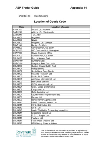
DB Sheetmetals Ltd‘K’ Factors For SolidworksMaterialThicknessBend RadiusNormalBendMild )2.6mm(16mmV)3.0mm4.0mm4.0mm6.0mm(40mm V)4.0mm(25mm V)8.0mmK 0.509K 0.395213K 0.355213K 0.455K 0.415K0.3794K 0.4325K 0.46425K 0.501K0.4855K 0.4855K 0.512K 0.4425K 5mm3.0mm1.3mm1.3mm1.3mm1.5mm1.5mm2.0mm3.0mmK 0.3955K 0.3555K 0.29601K 0.3801K 0.27326K 0.27324KK 1.5mm1.5mm2.0mm2.5mm3.0mmK 0.355K 0.454K 0.4855K0.55K 0.5500KK 0.591560.00.250.50.650.905.0mm5.0mmK0.52792.0St, SteelAluminiumAir BendCoin BendHem BendB/AK 0.6250.00.00.00.20.410.250.50.751.5K 0.625K 0.625K 0.625K 0.6251.01.51.752.03.07.16mmK 0.6250.00.00.00.250.00.00.00.01.5Bending is a manufacturing process by which metal can be deformed by plastically deforming the materialand changing its shape. The material is stressed beyond its yield strength but below its ultimate tensilestrength. There is little change to the materials surface area. Bending generally refers to deformation aboutone axis only.Bending is a flexible process by which a variety of different shapes can be produced though the use ofstandard die sets or bend brakes. The material is placed on the die, and positioned in place with stopsand/or gages. It is held in place with hold-downs. The upper part of the press, the ram with the appropriatelyshaped punch descends and forms the v-shaped bend.Bending is done using Press Brakes. Press Brakes can normally have a capacity of 20 to 200 tons toaccommodate stock from 1m to 4.5m (3 feet to 15 feet). Larger and smaller presses are used for diversespecialized applications. Programmable back gages, and multiple die sets currently available can makebending a very economical process.
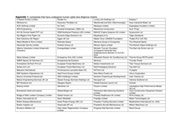
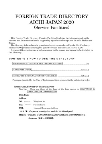
BEND ALLOWANCESWhen sheet metal is bent, the inside surface of the bend is compressed and theouter surface of the bend is stretched. Somewhere within the thickness of the metallies its Neutral Axis, which is a line in the metal that is neither compressed norstretched.BENDALLOWANCEAAWhat this means in practical terms is that if we want a work piece with a 90 degreebend in which one leg measures A, and the other measures B, then the total lengthof the flat piece is NOT A B as one might first assume. To work out what the lengthof the flat piece of metal needs to be, we need to calculate the Bend Allowance orBend Deduction that tells us how much we need to add or subtract to our leglengths to get exactly what we want.BBLt A B BAwhere:Lt is the total flat lengthA and B are shown in the illustrationBA is the bend allowance valueBENDDEDUCTIONLt A B - BDwhere:Lt is the total flat lengthA and B are shown in the illustrationBD is the bend deduction valueThe location of the neutral line varies depending on the material itself, the radius ofthe bend, the ambient temperature, direction of material grain, and the method bywhich it is being bent, etc. The location of this line is often referred to as the K factor.K-factor is a ratio that represents the location of the neutral sheet with respect to thethickness of the sheet metal part.tK-Factor t /TTThe only truly effective way of working out the correct bend allowance is to reverseengineer it by taking a measured strip of material, bending it, and then measuring it
to calculate the bend allowance. These bend allowance can be measured for manymaterials and scenarios and then tabulated so that the table can be used by CADprograms to produce accurate sheet-metal work.Many CAD programs, however, also work out bend allowances automatically byusing K-factor calculations.(Or Y-factor in the case of Pro-E where Y-factor K-factor * / 2).Bend allowances are calculated using a K-factor as follows:BA (R KT) A/180where:BA bend allowanceR inside bend radiusK K factor, which is t / TT material thicknesst distance from inside face to neutral sheetA bend angle in degrees (the angle through which the material is bent)This works extremely well and is pretty straight forward, providing we know thecorrect K-factor to use.Once again, the most accurate way of finding the correct K-factor to use in your CADprogram is by using the reverse engineering method described above, andcalculating the K-factor to use as described in the following section:
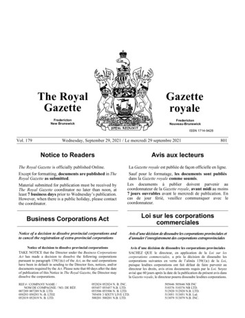
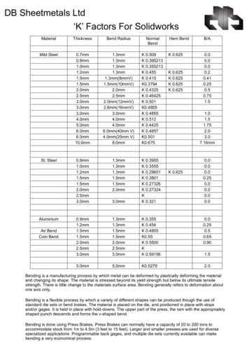
REVERSE ENGINEERING THE K-FACTORFirst, cut a strip of material and measure its length and thickness as accurately aspossible. The width of the strip is not that critical but generally somewhere around100mm (4 inches) or so usually does the trick.Then, bend the strip to 90 degrees, and measure its Length X and Length Y asshown in the diagram below.Note that it is very important to bend the sample piece in exactly the samemanner as you plan to bend your real pieces, so that whatever you measurenow becomes reproducible later.STEP 1nd eB e ng lAnd usBe adiRThicknessLength YTotal Flat LengthSTEP 2Length XThe bend radius can be extremely difficult to measure accurately but, in this case, isnot critical (within reasonable limits, of course!). The reason it is not critical is thatwhat we are interested in is a number to use in our CAD program that, with the bendradius used in our CAD program, will produce the results you are measuring in reallife.In other words the K-factor you calculate now will take into account any smallinaccuracies in the bend radius measurement and compensate for it. If, for example,we are using a Bend radius of 0.5 in our CAD program, it does not matter if our realtooling radius is actually 0.4, as the K-factor, which was worked out from our realtooling, corrects for this. The only implication of this is that we may occasionally get aK-factor that seems odd (higher than 0.5, for example) if our real radius is verydifferent from our CAD program radius. Remember though that most CAD programssuch as Solidworks only accept K-factor values from 0 to 1, so if the calculated Kfactor is outside these limits, then you may need to double-check your numbers.The correct K-factor to use in your CAD program can now be calculated as follows:BendDeduction Length X Length Y - Total Flat LengthOutSideSetBback (Tan(BendAngle / 2)) * (thickness BendRadius)BendAllowance (2 * OutSideSetBback) BendDeductionK-Factor (-BendRadius (BendAllowance / ( * BendAngle / 180))) / thicknessUsing this method will produce the most acceptable results other than by using abend table.There are however also some general rules of thumb that can be used for K-factorsthat will generally give results that are within acceptable tolerances for non-precisionsheet metal work. Some of these sample K-factors are given in the methods ofbending section below.
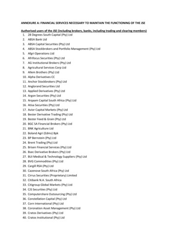
PRINCIPLE TYPES OF BENDINGAIR BENDINGAir Bending is a bending process in which the punch touches the work piece and thework piece does not bottom in the lower cavity. As the punch is released, the workpiece springs back a little and ends up with less bend than that on the punch (greaterincluded angle). This is called spring-back.The amount of spring back depends on the material, thickness, grain and temper.The spring back will usually range from 5 to 10 degrees. The same angle is usuallyused in both the punch and the die to minimize set-up time. The inner radius of thebend is the same as the radius on the punch.In air bending, there is no need to change any equipment or dies to obtain differentbending angles because the bend angles are determined by the punch stroke. Theforces required to form the parts are relatively small, but accurate control of thepunch stroke is necessary to obtain the desired bend angle.BlankPunchBlankPunchDieK-Factor Rule of thumb for Air BendingRadiusSoft-material0 to thickness0.33Thickness to 3 x thickness 0.4Greater than 3 x thickness 0.5DieMedium Material0.380.430.5Hard Material0.40.450.5BOTTOMINGBottoming is a bending process where the punch and the work piece bottom on thedie. This makes for a controlled angle with very little spring back. The tonnagerequired on this type of press is more than in air bending. The inner radius of thework piece should be a minimum of 1 material thickness.In bottom bending, spring-back is reduced by setting the final position of the punchsuch that the clearance between the punch and die surface is less than the blankthickness. As a result, the material yields slightly and reduces the spring-back.Bottom bending requires considerably more force (about 50% 60% more) than airbending.
BlankBlankPunchPunchDieK-Factor Rule of thumb for BottomingRadiusSoft-material0 to thickness0.42Thickness to 3 x thickness 0.46Greater than 3 x thickness 0.5DieMedium Material0.440.470.5Hard Material0.460.480.5COININGCoining is a bending process in which the punch and the work piece bottom on thedie and compressive stress is applied to the bending region to increase the amountof plastic deformation. This reduces the amount of spring-back. The inner radius ofthe work piece should be up to 0.75 of the material thickness.BlankPunchBlankPunchDieDieK-Factor Rule of thumb for CoiningRadiusSoft-material0 to thickness0.38Thickness to 3 x thickness 0.44Greater than 3 x thickness 0.5Medium Material0.410.460.5Hard Material0.440.470.5
TIPS AND TRICKSGeneral bending guidelines are as follows:The bend radius should, if possible, be kept the same for all radiuses in thepart to minimize set up changes.For most materials, the ideal minimum inner radius should be at least 1material thickness.As a general rule, bending perpendicular to the rolling direction is easier thanbending parallel to the rolling direction. Bending parallel to the rolling directioncan often lead to fracture in hard materials. Thus bending parallel to therolling direction is not recommended for cold rolled steel Rb 70. And nobending is acceptable for cold rolled steel Rb 85. Hot rolled steel canhowever be bent parallel to the rolling direction.The minimum flange width should be at least 4 times the stock thickness plusthe bending radius. Violating this rule could cause distortions in the part ordamage to tooling or operator due to slippage.Min Flange Width 4 x Thickness Bend radiusSlots or holes too close to the bend can cause distortion of these holes. Holesor slots should be located a minimum of 3 stock thickness plus the bendradius. If it is necessary to have holes closer, then the hole or slot should deextended beyond the bend line.DD 3 x Thickness Bend radiusDimensioning of the part should take into account the stack up of dimensionsthat can happen and mounting holes that can be made oblong should be.Parts should be inspected in a restrained position, so that the natural flexureof the parts does not affect measurements. Similarly inside dimensions in aninside bend should be measured close to the bend.
OTHER COMMON TYPES OF BENDINGV BendingIn V-bending, the clearance between punch and die is constant (equal to thethickness of sheet blank). It is used widely. The thickness of the sheet ranges fromapproximately 0.5 mm to 25 mm.BlankBlankPunchPunchDieDieU DIE BENDINGU-die bending is performed when two parallel bending axes are produced in thesame operation. A backing pad is used to force the sheet contacting with the punchbottom. It requires about 30% of the bending force for the pad to press the sheetcontacting the punch.BlankPunchBlankPunchDiePadPadDieWIPING DIE BENDINGWiping die bending is also known as flanging. One edge of the sheet is bent to 90while the other end is restrained by the material itself and by the force of blank-holderand pad. The flange length can be easily changed and the bend angle can becontrolled by the stroke position of the punch.PadPadPunchPunchDieBlankDieBlank
DOUBLE DIE BENDINGDouble die bending can be seen as two wiping operations acting on the work pieceone after another. Double bending can enhance strain hardening to reduce springback.PadPadPunchPunchDieBlankDieBlankROTARY BENDINGRotary bending is a bending process using a rocker instead of the punch. Theadvantages of rotary bending are:a) Needs no blank-holderb) Compensates for spring-back by over-bendingc) Requires less forced) More than 90 degree bending angle is availableUpper DieUpper DieRockerRockerBlankLower DieLower DieBlank
PRINCIPLE TYPES OF BENDING AIR BENDING Air Bending is a bending process in which the punch touches the work piece and the work piece does not bottom in the lower cavity. As the punch is released, the work piece springs back a little and ends up with less bend than that on the punch (greater