Transcription
Data SheetApril 1998T7290A DS1/T1/CEPT/E1 Line InterfaceFeatures Fully integrated DS1/T1/CEPT/E1 line interface For use in systems that are compliant with CB119,AT&T PUB 43801, AT&T PUB 43802, AT&T PUB62411, TR-TSY-000170, TR-TSY-000009, ITU-TG.703, G.735, G.823, and I.431 specifications Dual-rail system interface On-chip transmit equalization On-chip jitter attenuator Monolithic clock recovery with frequencyacquisition aide High jitter accommodation ( 0.4 U.I.) No external crystal required Three clocking modes to accommodate multiplesystem clocking requirements Multiple link-status and alarm features Microprocessor interface option AIS (blue alarm) transmission Loopback modes for fault isolation Minimal external circuitry requiredDescriptionThe Lucent Technologies Microelectronics GroupT7290A DS1/T1/CEPT/E1 Line Interface is a fullyintegrated line transceiver capable of operation at thedomestic DS1/T1 carrier rate (1.544 Mbits/s) or theinternational CEPT/E1 rate (2.048 Mbits/s). TheT7290A device combines features found in existingline-interface devices with additional desirable features.The on-chip, low-impedance output drivers provideshaped waveforms to the transformer, guaranteeingtemplate conformance. The T7290A device interfaces to the digital cross connect (DSX) at lengths upto 655 feet during DS1 operation and interfaces toline impedances of 75 Ω or 120 Ω during CEPT operation. The device line interface also can transmitwaveforms compatible with T1 lines.The T7290A line interface provides phase-lockedloop clock recovery and data retiming on receiveddata. Also, on-chip, selectable jitter attenuation isavailable. The jitter attenuator can be placed in thereceive or transmit data path. No external crystalsare required with the T7290A device.Digital control circuitry allows for multiple loopbacks,testing, and alarm status monitoring. A microprocessor interface option allows for either control via amicroprocessor or direct pin-selectable control(hardware mode).The T7290A device is manufactured by using a lowpower CMOS technology and is available in a 28-pin,plastic SOJ package or a 28-pin, plastic DIP package.Note: Modification of an existing T7290 applicationmay be required when migrating to a T7290Abased architecture. The functions of the TBS,TSC, LP1, DLOS, and LOS pins have beenchanged or modified. Please refer to theT7290A Migration from T7290 section of thisdata sheet.Downloaded from Arrow.com.
T7290A DS1/T1/CEPT/E1 Line InterfaceData SheetApril 1998Table of ContentsContentsPageFeatures . 1Description. 1Pin Information . 4Receiver . 6Data Interface . 6Clock Recovery and Data Retiming. 6Frequency-Acquisition Aide. 6Jitter. 7Data Patterns. 8Loss of Signal . 8Transmitter . 8Output Pulse Shape . 8Output Pulse Generation . 10Jitter Attenuator . 11Alarms and Maintenance. 13Digital Loss of Signal (DLOS). 13Output Loss of Signal (OUT-LOS). 13Jitter Attenuator Alarm (ESA) . 14Transmitter Short Circuit. 14AIS (Blue Signal) Generator . 14Loopbacks . 14Microprocessor Interface . 14In-Circuit Testing . 14Absolute Maximum Ratings. 15Handling Precautions . 15Electrical Characteristics . 16Operating Conditions. 16Timing Characteristics . 17Applications . 19Line Termination. 19Outline Diagrams. 2128-Pin, Plastic SOJ. 2128-Pin, Plastic DIP. 22Ordering Information. 22T7290A Migration from T7290. 23DS98-190TIC Replaces DS97-197TIC to Incorporate the Following Updates. 232Downloaded from Arrow.com.Lucent Technologies Inc.
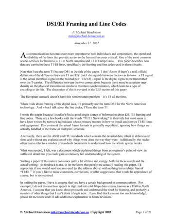
Lucent Technologies Inc.Downloaded from Arrow.com.R1T1ALOSR2T2TRANSMITMONITORALOSTSCTRI DRIVERSOUT-LOS2TBSEXCLKUGRCLKLOSS OFCLOCKPULSEEQUALIZEREC1 EC2 TERATTENEXCLKUGRCLKMODE1MODE2 LP2SCLKMODE1 LP1µPINTERFACEEXCLK242LP32VDDA, GNDAVDDD, ATA,TNDATAESARCLKRPDATA,RNDATAIN-LOSData SheetApril 1998T7290A DS1/T1/CEPT/E1 Line InterfaceDescription (continued)5-2484(C)r.6Figure 1. Block Diagram3
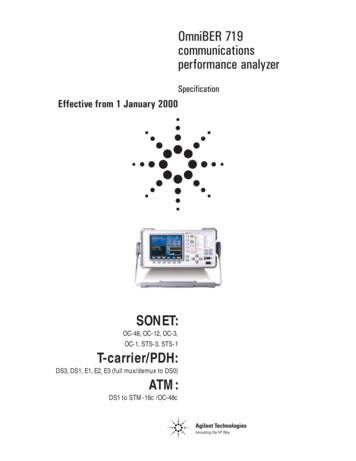
Data SheetApril 1998T7290A DS1/T1/CEPT/E1 Line InterfacePin 1316EXCLKOUT-LOS1415CST7290A5-1810 (F).aFigure 2. Pin DiagramTable 1. Pin DescriptionsPin1, 27, 28SymbolEC1, EC3, EC2Type*Name/FunctionIdEqualizer/Rate Control 1—3. Three control leads for selecting transmitequalization.2TRIIu3VDDA—4567, 8GNDAR1T1MODE2, MODE1—IIId9, 10LOOPB, LOOPAId11TBSId12IN-LOSO3-State (Active-Low). This pin is set low to configure all output buffers intoa high-impedance state during in-circuit testing.5 V 5% Analog Supply. The powerup rise time (0 V to 4.75 V) must beless than 15 ms.Analog Ground.Receive Bipolar Ring. Negative bipolar receive data.Receive Bipolar Tip. Positive bipolar receive data.Mode Select 2 and 1. Two control leads for selecting clock and data pathsthrough the jitter attenuator.Loopback Control B and A. Two control leads for selecting clock and dataloopback paths.Transmit Blue Signal (AIS). This pin is set high to transmit the blue signal(all 1s). A remote loopback (LP2) has priority over the transmit blue signal.Input Loss of Signal. This pin is set high if analog loss of signal at thereceiver inputs is detected or if digital loss of signal of the recovered data isdetected. IN-LOS can be tied directly to TBS to initiate a transmit blue signalupon loss of signal.* I input, O output, Iu input with pull-up, Id input with pull-down.4Downloaded from Arrow.com.Lucent Technologies Inc.
Data SheetApril 1998T7290A DS1/T1/CEPT/E1 Line InterfacePin Information (continued)Table 1. Pin Descriptions (continued)Pin13SymbolESAType*Name/FunctionOJitter Attenuator Alarm. This pin is set high if the phase jitter of the incoming signal exceeds the tolerance of the jitter attenuator's buffer. This mayresult in a loss of receive data.OOutput Loss of Signal. This pin is set high when either the transmit clock(TCLK) or the smoothing clock (SCLK) output of the jitter attenuator R2GNDDO—Chip Select for Microprocessor Interface (Active-Low). CS loads datainto the device on its falling edge and latches the data on its rising edge. CSis set low for hardware mode.External Clock. DS1/T1 clock signal (1.544 MHz 130 ppm) or CEPT/E1clock signal (2.048 MHz 80 ppm) for transmit blue signal, jitter attenuatorcalibration, and PLL acquisition aid. EXCLK must be an independent clockto guarantee device performance for all specifications. This clock should becontinuously active (i.e., ungapped and unswitched) and void of jitter for theabove features to operate.Transmit Clock. DS1/T1 clock signal (1.544 MHz 130 ppm) or CEPT/E1clock signal (2.048 MHz 80 ppm).Transmit Positive Data. DS1/T1 (1.544 Mbits/s) or CEPT/E1(2.048 Mbits/s) positive bipolar data.Transmit Negative Data. DS1/T1 (1.544 Mbits/s) or CEPT/E1(2.048 Mbits/s) negative bipolar data.Receive Clock. Recovered receive clock signal for the terminal equipment.Receive Positive Data. DS1/T1 (1.544 Mbits/s) or CEPT/E1(2.048 Mbits/s) recovered positive data (NRZ).Receive Negative Data. DS1/T1 (1.544 Mbits/s) or CEPT/E1(2.048 Mbits/s) recovered negative data (NRZ).Transmit Bipolar Tip. Positive bipolar transmit data.5 V 5% Digital Supply. The powerup rise time (0 V to 4.75 V) must beless than 15 ms.Transmit Bipolar Ring. Negative bipolar transmit data.Digital Ground.* I input, O output, Iu input with pull-up, Id input with pull-down.Lucent Technologies Inc.Downloaded from Arrow.com.5
Data SheetApril 1998T7290A DS1/T1/CEPT/E1 Line InterfaceReceiverFrequency-Acquisition AideData InterfaceFor robust operation, PLL is enhanced with a frequency-acquisition capability. The frequency-acquisition circuitry is intended to guarantee proper phaselocking during start-up situations, such as powerup ordata activation. Once the T7290A device is phaselocked to data, the frequency-acquisition mode is notactivated unless a digital loss of signal occurs, in whichcase RCLK is frequency-locked/phase-locked toEXCLK. RCLK is always active and does not have anyinstantaneous phase hits or discontinuities.The receive line-interface transmission format of theT7290A device is alternate mark inversion (AMI). Thereceive digital output format is dual-rail, nonreturn tozero (NRZ). Receiver specifications are shown inTable 2.Clock Recovery and Data RetimingThe bipolar input signals from T1 and R1 are peakdetected and sliced by the receiver front end. Timingrecovery is performed by a phase-locked loop (PLL)that locks an internal free-running, current-controlledoscillator (ICO) to the data-rate component. EC1, EC2,and EC3 rate control inputs must be set appropriatelyfor DS1 or CEPT/E1 operation.A continuously active (i.e., ungapped and unswitched)reference clock must be present at EXCLK to enablethe frequency-acquisition circuitry. EXCLK must be anindependent reference such as an oscillator or systemclock for proper operation. The EXCLK clock frequencymust be 1.544 MHz 130 ppm for T1/DS1 operation or2.048 MHz 80 ppm for CEPT/E1 operation.Table 2. Receiver SpecificationsParameterReceiver Sensitivity:*DS1CEPTAnalog LOS Level:DS1CEPTPLL:†3 dB BandwidthPeakingICO Free-run Frequency ErrorInput Density .480.28——VpVp———331.2——2 ss:§Return51 kHz—102 kHz102 kHz—2.048 MHz2.048 MHz—3.072 MHz* Values shown are for flat loss only. Receiver also meets ITU-T G.703 interface immunity test (6 dB cable loss with–18 dB interference) for CEPT/E1 operation.† Transfer characteristics (1/8 input).‡ The maximum number of consecutive zeros 15.§ Return loss specifications according to ITU-T G.703/RC6367A (CEPT only).6Downloaded from Arrow.com.Lucent Technologies Inc.
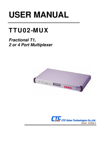
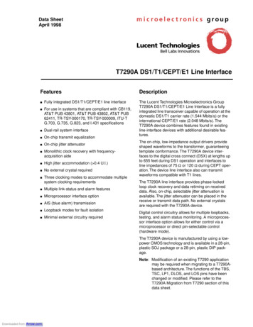
Data SheetApril 1998T7290A DS1/T1/CEPT/E1 Line InterfaceReceiver (continued)JitterPLL is designed to accommodate large amounts of input jitter with high power supply rejection for operation innoisy environments. PLL has a minimum input jitter tolerance exceeding all requirements shown in Figure 3. Themeasured receiver jitter tolerance for DS1 and CEPT operation is also shown in Figure 3, with pseudorandom inputdata (215 – 1) and with EXCLK synchronous with the data source. The receiver transfers incoming jitter to RCLKwith no more than 2 dB of gain at any frequency, which can be further reduced with the jitter attenuator.500.0TRI-TSY-000170, PUB 43801PUB 62411PEAK-TO-PEAK JITTER MAGNITUDE (U.I.)PUB 62411 (LOOP TIMED)100.0MINIMUM JITTERATTENUATOR PERFORMANCE50.028.0MEASURED RECEIVERCEPT PERFORMANCE(JITTER ATTENUATORNOT ACTIVE)TR-TSY-000009,PUB 4380210.0MEASUREDRECEIVER DS1PERFORMANCE(JITTER ATTENUATORNOT ACTIVE)5.01.0ITU-T G.8230.50.1110100100010,000JITTER FREQUENCY (Hz)100,0005-1157(C)r.4Data Points (Hz, U.I.)ITU-TG.823TR-TSY-000170,AT&T PUB43801TR-TSY-000009,AT&T PUB43802AT&TPUB624111, 2.920, 1.52.4k, 1.518k, 0.2100k, 0.2—————10, 30010k, 0.350k, 0.3———————10, 5500, 58k, 0.140k, 0.1——————1, 13848, 13810k, 0.2100k, 0.2——————AT&TPUB62411LoopedTimed1, 13885, 13810k, 0.4100k, 0.4——————MeasuredReceiver DS1Performance(BER 10–6)MeasuredReceiver CEPTPerformance(BER 10–6)2.0k, 6.515.0k, 2.038.0k, 1.1210k, 0.9715k, 0.8420k, 0.6630k, 0.5240k, 0.4970k, 0.48100k, 0.482.0k, 9.435.0k, 2.848.0k, 1.7010k, 1.3815k, 1.0020k, 0.8430k, 0.5740k, 0.4870k, 0.47100k, 0.47Figure 3. PLL Jitter Tolerance RequirementsLucent Technologies Inc.Downloaded from Arrow.com.7
Data SheetApril 1998T7290A DS1/T1/CEPT/E1 Line InterfaceReceiver (continued)detector output becomes active. Hysteresis (250 mV) isprovided in the analog detector to eliminate ALOSchattering. Either the analog or the digital detector setsIN-LOS high.Data PatternsAny data pattern with a minimum long-term 1s densityof 12.5% with 15 or fewer consecutive 0s is allowed.The time required to detect analog loss of signal(ALOS) depends on the incoming signal amplitudebefore it disappears. Typical ALOS detection times aregiven in Table 3.Loss of SignalTable 3. Typical ALOS Detection TimesBoth digital (DLOS) and analog (ALOS) loss-of-signaldetection is used in the T7290A device. The digital signal detector is described later under the Alarms andMaintenance section. The analog signal detector usesthe output of the receiver peak detector to determine ifa signal is present at T1 and R1. If the input amplitudedrops below approximately 0.48 Vp for DS1/T1 operation or 0.28 Vp for CEPT/E1 operation, the analogSignal Amplitude(Vp)3.62.51.71.0Typical ALOSDetection Time (ms)5.03.72.81.4TransmitterOutput Pulse ShapeTransmitter specifications are shown in Table 4. The T1 pulse shape template is specified at the network interfaceas shown in Figure 4. The DS1 pulse shape template is specified at the DSX and is illustrated in Figure 5. CEPTtransmit waveforms at the device output conform to the template shown in Figure 6.Table 4. Transmitter SpecificationsParameterOutput Pulse Amplitude:*T1DS1 (at DSX)CEPT (into 75 Ω)CEPT (into 120 Ω)Output Pulse Width:T1DS1CEPTOutput Power Levels:T1 (3 kHz band at 772 kHz)T1 (3 kHz band at 1544 kHz)†DS1 (2 kHz band at 772 kHz)DS1 (2 kHz band at 1544 kHz)†Positive/Negative Pulse Imbalance:DS1‡CEPT§CEPT Zero Level**Return Loss:††51 kHz—102 kHz102 kHz—2.048 MHz2.048 MHz—3.072 dB———0.1210.5 510dB%%81410——————dBdBdB*†‡In accordance with the interfaces described in the Line Termination section under Applications.Below the power at 772 kHz.Total power difference.§ Percentage of the pulse amplitude and pulse width.** Percentage of the pulse amplitude.†† Meets CH-PTT return loss specifications (CEPT only).8Downloaded from Arrow.com.Lucent Technologies Inc.
Data SheetApril 1998T7290A DS1/T1/CEPT/E1 Line InterfaceTransmitter (continued)Output Pulse Shape (continued)NORMALIZED AMPLITUDE (A)NORMALIZED AMPLITUDE 05007501000TIME (ns)TIME (ns)5-1604(F)r.3T1 Isolated-Pulse Corner Points According toFCC Part 68Maximum ——Minimum –0.261100–0.051250–0.05Note: Successive corner points are joined by straight lines.Figure 4. T1 Isolated-Pulse TemplateLucent Technologies Inc.Downloaded from Arrow.com.12505-1160(C)r.6DSX-1 Pulse Template Corner Points Accordingto CB119Maximum ———Minimum –0.201100–0.051250–0.05Note: Successive corner points are joined by straight lines.Figure 5. DSX-1 Isolated-Pulse Template9
Data SheetApril 1998T7290A DS1/T1/CEPT/E1 Line InterfaceTransmitter (continued)Output Pulse Shape (continued)269 ns(244 25)20%10%V 100%194 ns(244 – 50)10%NOMINAL PULSE20%50%244 ns219 ns(244 – 25)10%10%0%10%10%20%488 ns(244 244)5-3145(C)r.7Note: V corresponds to the nominal peak value.Figure 6. ITU-T G.703 Pulse TemplateOutput Pulse GenerationThe transmitter accepts a clock with positive and negative data (dual-rail NRZ format) and converts the signal to abalanced bipolar data signal (AMI format). Positive 1s are produced by a positive pulse on device pin T2, and negative 1s are produced by a positive pulse on device pin R2. Binary 0s are converted to null pulses. All pulse shapesare controlled on-chip according to equalizer control inputs, as defined in Table 5. Transmitter specifications areshown in Table 4.Table 5. Equalizer/Rate ControlServiceT1ClockRate1.544 MHzDS11.544 MHzCEPT2.048 MHzTransmitterEqualization*—0 ft.—131 ft.131 ft.—262 ft.262 ft.—393 ft.393 ft.—524 ft.524 ft.—655 ft.75 Ω120 ΩMaximumCable 10011EC301010101*Distance to DSX in feet for 22-Ga. PIC (ABAM) cable (DS1 only). Use maximum loss figures for other cable types.† dB at 772 kHz.‡ According to FCC Part 68, Subpart D, Option A for 0 dB line build-out.10Downloaded from Arrow.com.Lucent Technologies Inc.
Data SheetApril 1998T7290A DS1/T1/CEPT/E1 Line InterfaceJitter AttenuatorJitter transfer functions describe the amount of jitterthat is transferred from the input to the output of thespecified equipment. The jitter transfer functions areaffected by the jitter attenuator circuitry, which can beplaced in the receive data path, placed in the transmitdata path, or bypassed. Placement of this circuit is controlled as described in Table 6. The external clock(EXCLK) must be present for the attenuation functionto operate. When attenuation is selected, the T7290Adevice exhibits a jitter transfer function that has nopeaking and a single 3.6 Hz pole frequency (DS1) or4.8 Hz pole frequency (CEPT). Figure 7 displays a typical DS1 jitter transfer function for a constant input jitteramplitude of 2.0 U.I. peak-to-peak.The amount of generated output jitter when no input jitter is present is measured by using the scheme shownin Figure 8. The jitter filters depicted represent theAT&T PUB 62411 specification for a 1.544 MHz datarate. The jitter produced at the labeled points does notexceed the following peak-to-peak levels: 0.05 U.I. atpoint 1, 0.025 U.I. at point 2, 0.025 U.I. at point 3, and0.02 U.I. at point 4. A similar test can be performed forITU-T I.431 qualification at the 2.048 MHz data rate, inwhich two jitter filters are 20 Hz—100 kHz (0.125 U.I.)and 700 Hz—100 kHz (0.02 U.I.).The jitter tolerance of the attenuator meets the requirements of the TR-TSY-000009, AT&T PUB 43802, andITU-T G.823 (see Figure 3). The attenuator alsoensures that jitter accommodation is a minimum of28 U.I. peak-to-peak (DS1) or 40 U.I. peak-to-peak(CEPT) (1 U.I. 648 ns [T1/DS1] or 488 ns [CEPT])during attenuation. The jitter attenuation function isidentical when placed in either transmit or receive path.Ideally, the tolerance of the attenuator is 32 bits(64 U.I.). However, if f (Hz) frequency (EXCLK) –frequency (input clock) and N 23 (DS1) or 30.5(CEPT), then the tolerance is degraded and equals:ABS ( f )64 – 2 RND – UP ------------------------- 1 (U.I.)NFigure 9 shows the phase step response (DS1) of theattenuator given f. The response is based on a phaseoffset (U.I.) generated by the read pointer of the buffer.It is this phase offset that degrades the attenuator's tolerance.40 dB/DECADEJITTER ATTENUATION (dB)0–10ITU-T G.735,ITU-T I.43120 dB/DECADE–20TR-TSY000009,PUB 43802TYPICALPERFORMANCE20 dB/DECADE–30–40–5020 dB/DECADE–60–7011040 1003501k 2.5k40015k10kJITTER FREQUENCY (Hz)5-1311(C)r.4Data Points (Hz, dB)TR-TSY-000009,AT&T PUB 438021, 0.1350, 0.12.5k, –33.615k, –49.2ITU-T G.735,ITU-T I.43110, 0.540, 0.5400, –19.515k, –19.5Figure 7. Jitter Transfer Function of the Jitter AttenuatorLucent Technologies Inc.Downloaded from Arrow.com.11
Data SheetApril 1998T7290A DS1/T1/CEPT/E1 Line InterfaceJitter Attenuator (continued)When the T7290A device is used only as a jitter attenuator, loopback 1 (LP1) should be active and the attenuatormust be placed in the transmit path (MODE1:2 01).Table 6. Connectivity of Jitter AttenuatorConnectivity of Jitter Attenuator*MODE1MODE2Transmit PathReceive Path001010Test Mode‡11Bypass†* The jitter attenuator must be enabled after VDD exceeds 4.75 V during device powerup.† Jitter attenuator is powered down during this mode (see Table 8 under the Electrical Characteristics section).‡ Not used for normal operation.FILTERS(SLOPES MUST BE20 dB PER DECADE)410 HzTO EACH POINT8 kHzPEAKDETECTOR3MEASUREDSIGNALJITTERDETECTOR8 Hz(700 Hz)40 kHz(100 kHz)10 Hz(20 Hz)40 kHz(100 kHz)TRUE RMSVOLTMETER2TO EACH POINT1SPECTRUMANALYZER5-1163(F)r.2Figure 8. Measurement of Generated Jitter12Downloaded from Arrow.com.Lucent Technologies Inc.
Data SheetApril 1998T7290A DS1/T1/CEPT/E1 Line InterfaceJitter Attenuator (continued)READ COUNTER OFFSET (U.I.)PHASE STEP RESPONSE (I fI 0 400 Hz)20151050050100150TIME (ms)5-2485(C)r.3Figure 9. Jitter Attenuator Phase ResponseAlarms and MaintenanceOutput Loss of Signal (OUT-LOS)Digital Loss of Signal (DLOS)An output loss of signal (OUT-LOS 1) is indicated ifeither the transmit clock (TCLK) or the smoothing clock(SCLK) output of the jitter attenuator is absent. If the jitter attenuator is placed in the transmit path, SCLK ismonitored. If the jitter attenuator is not used in thetransmit path, TCLK is monitored. For every ten clockperiods of the PLL oscillator clock, denoted asUGRCLK in Figure 1, a strobe is generated. If a singletransmit clock period occurs between strobes, thenOUT-LOS 0. If no transmit clock period occursbetween strobes, then OUT-LOS 1, and the outputdrivers (T2 and R2) are placed into a high-impedancestate and no data is transmitted. UGRCLK is alwayspresent, even in the absence of both EXCLK andT1/R1 input data; therefore, UGRCLK is the most suitable clock for monitoring OUT-LOS.A digital loss of signal (DLOS 1) is indicated if 128 ormore consecutive 0s occur in the receive data streamduring DS1/T1 operation. During CEPT operation, aDLOS is indicated when 32 or more consecutive 0soccur in the receive data stream. DLOS is then deactivated when the ones density exceeds 12.5% and thereare no more than 15 consecutive 0s (T1, DS1, andCEPT), signifying the return of good signal. DLOSdeactivation monitors the data in fixed 32-bit windows.Each window must have at least four 1s with no morethan 15 consecutive 0s. Consecutive 0s are also monitored across the window boundary. This condition mustpersist for two consecutive 32-bit windows, at whichtime DLOS is deactivated at the end of the window.Upon DLOS detection, RCLK is phase-locked to theexternal clock (EXCLK) so that other system devicesslaved to the line clock continue to operate withoutinstantaneous phase hits or discontinuities. Either ananalog loss of signal (ALOS) or a digital loss of signal(DLOS) activates the IN-LOS output pin.Lucent Technologies Inc.Downloaded from Arrow.com.13
Data SheetApril 1998T7290A DS1/T1/CEPT/E1 Line InterfaceAlarms and Maintenance (continued)does not corrupt the looped data. The IN-LOS alarm stillmonitors the entire receive function.Jitter Attenuator Alarm (ESA)A remote loopback (LP2) loops the recovered clock andretimed data into the transmitter and back onto the line.The receive front end, receive PLL, jitter attenuator (ifengaged), and transmit driver circuitry are all exercised.The transmit clock, transmit data, and TBS inputs areignored. Valid receive output data continues to be sentto RPDATA and RNDATA. This loop can be used to isolatefailures between systems.A jitter attenuator alarm (ESA 1) is indicated if thephase jitter exceeds the tolerance of the jitter attenuator. Bit errors occur when ESA is active. This signal isasserted until error-free operation resumes. SeeFigure 9 to determine the tolerance limits of the attenuator.Transmitter Short CircuitA transmitter monitor is provided to detect nonfunctioning links and protect the device from damage. If one ofthe transmitter's line drivers (T2 or R2) is shorted to thepower supply or ground, or if T2 and R2 are shortedtogether, internal circuitry protects the device fromdamage. After 35 transmit clock cycles, the transmitteris powered up in its normal operating mode. The driversattempt to correctly transmit the next data bit ( 1, 0, or–1). If the short is still present, the transmitter is againinternally protected for 35 transmit clock cycles. Thisprocess is continuously repeated until the short has disappeared. The TSC alarm is not available off-chip.A digital local loopback (LP3) directly loops the transmitclock and data to the receive clock and data output pins.The blue signal can be transmitted when in this loopback.LP3 (rather than LP1) must be selected if MODE2 0.Table 7. Loopback ControlOperationNormalDigital Local LoopbackRemote LoopbackLocal LoopbackSymbol LOOPA LOOPB—00LP301LP2*10LP111* TBS is ignored.Microprocessor InterfaceAIS (Blue Signal) GeneratorWhen the transmit blue signal is set (TBS 1), a continuous stream of bipolar 1s is transmitted onto the linesynchronous with EXCLK. The TPDATA and TNDATAinputs are ignored during this mode. If the IN-LOSoutput is externally connected to the TBS input, anIN-LOS error initiates a transmit blue signal as long asIN-LOS 1. Also, TBS input is ignored when a remoteloopback is selected. There is no microprocessor interface for the TBS input, i.e., any change on the TBS pinis fed directly into the device and is not impeded by theCS function.A chip-select input (CS) configures the device in eitherhardware mode or microprocessor mode. The chip-selectfunction applies to the following inputs: MODE1, MODE2,EC1, EC2, EC3, LOOPA, and LOOPB. In
T7290A DS1/T1/CEPT/E1 Line Interface Features n Fully integrated DS1/T1/CEPT/E1 line interface n For use in systems that are compliant with CB119, AT&T PUB 43801, AT&T PUB 43802, AT&T PUB 62411, TR-TSY-000170, TR-TSY-000009, ITU-T G.703, G.735, G.823, and I.431 speciÞcations n Dual-rail system interface n On-chip transmit equalization n