Transcription
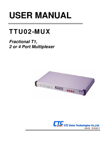
USER MANUALTTU02-MUXFractional T1,2 or 4 Port Multiplexer
The information contained in this document is subject to change without prior notice.TRADEMARKSMicrosoft is a registered trademark of Microsoft Corp.HyperTerminal is a registered trademark of Hilgraeve Inc.WARNING:This equipment has been tested and found to comply with the limits for a Class A digital device, pursuant to Part 15 of theFCC Rules. These limits are designed to provide reasonable protection against harmful interference when the equipment isoperated in a commercial environment. This equipment generates, uses, and can radiate radio frequency energy and if notinstalled and used in accordance with the instruction manual may cause harmful interference in which case the user will berequired to correct the interference at his own expense. NOTICE: (1) The changes or modifications not expressivelyapproved by the party responsible for compliance could void the user's authority to operate the equipment. (2) Shieldedinterface cables and AC power cord, if any, must be used in order to comply with the emission limits.CISPR PUB.22 Class A COMPLIANCE:This device complies with EMC directive of the European Community and meets or exceeds the following technicalstandard. EN 55022 - Limits and Methods of Measurement of Radio Interference Characteristics of Information TechnologyEquipment. This device complies with CISPR Class A.WARNING:This is a Class A product. In a domestic environment this product may cause radio interference in which case the user maybe required to take adequate measures.CE NOTICEMarking by the symbol CE indicates compliance of this equipment to the EMC directive of the European Community. Suchmarking is indicative that this equipment meets or exceeds the following technical standards:EN 55022:1994/A1:1995/A2:1997 Class A and EN61000-3-2:1995, EN61000-3-3:1995 and EN50082-1:1997
CTC Union Technologies Co., Ltd.Far Eastern Vienna Technologies Center(Neihu Technology Park)9F, No. 60, Zhouzi Street, Neihu, Taipei, TaiwanPhone:(886) 2.2659.1021 Fax:(886) 2.2799.1355E-mail: info@ctcu.comhttp://www.ctcu.comTTU02-MUX 4 Port MUX, Fractional T1(DS1), Installation and Operation ManualVersion 1.0 Sep 2000 PrintingVersion 1.0b Mar 2003 PrintingVersion 1.0c June 2004 Printing updating the latest I/F modulesThis manual supports the following models:TTU02-MUX.2-XX-AC, 2 Port MUX, universal ACTTU02-MUX.4-XX-AC, 4 Port MUX, universal ACTTU02-MUX.2-XX-DC, 2 Port MUX, DC modelTTU02-MUX.4-XX-DC, 4 Port MUX, DC modelImportant Update NoticeCommencing with production of the TTU02-MUX in March 2000, the Sub T1 Link has become anoption. To incorporate this feature, firmware changes were made that moved the MAIN T1 link fromthe interface card to the mother PCB and SUB T1 link from the mother PCB to the interface card.Changes were also made to the unit back panel graphics to reflect the new positions. Note that on allnew production, the Main T1 is below the Sub T1. The unit may now be ordered without the Sub T1feature if it is not required. While referring to the manual for the TTU02-MUX, please note thesedifferences in graphics and table settings for any older models.June 2004 notice: As of this printing, the sub-T1 is now a standard feature on all models.
TABLE OF CONTENTSCHAPTER 1. INTRODUCTION . 11.1 INTRODUCTION 11.2 FUNCTION DESCRIPTION 11.3 TYPICAL SYSTEM APPLICATIONS . .31.4 T1(DS1) SIGNAL STRUCTURE .41.5 TTU02-MUX CAPABILITIES 51.6 TECHNICAL SPECIFICATIONS 8CHAPTER 2. INSTALLATION . 132.1 GENERAL .132.2 SITE PREPARATION . .132.3 MECHANICAL ASSEMBLY . .132.4 ELECTRICAL INSTALLATION 132.5 DATA INTERFACE MODULE REPLACEMENT . 15CHAPTER 3. FRONT PANEL OPERATION 173.1 GENERAL 173.2 CONTROLS AND INDICATORS .173.3 LCD MENU OPERATION 18CHAPTER 4. CONTROL PORT OPERATION . 294.1 GENERAL .294.2 TERMINAL CONNECTION 294.3 MENU SYSTEM DETAIL 30i
TABLE OF CONTENTSCHAPTER 5. TEST AND DIAGNOSTICS 5.1 GENERAL .61615.2 STATUS INDICATORS AND MESSAGES . 615.3 USER ACTIVATED LOOPBACK 64CHAPTER 6. TROUBLESHOOTING INSTRUCTIONS . 71APPENDIX A. DIP SWITCH SETTING . 73A.1 DSW1 SETTING . 73A.2 JUMPER CHASS1 FRAME GROUND 73APPENDIX B. CONNECTORS & I/F Modules . . 75B.1 T1(DS1) LINE CONNECTORS . 75B.2 X.21 USER DATA CHANNEL CONNECTOR . 76B.3 V.35 USER DATA CHANNEL CONNECTOR . 77B.4 RS-530 USER DATA CHANNEL CONNECTOR . 78B.5 RS-232 USER DATA CHANNEL CONNECTOR 79B.6 RS-530 to RS-449 ADAPTER CABLE . 80B.7 G.703/64K Codirectional USER DATA CHANNEL CONNECTOR . 81B.8 NRZ/BNC USER DATA CHANNEL CONNECTOR . . 82B.9 RS-232/ALARM PORT CONNECTOR . 83B.10 ET10 10BASE-T BRIDGE USER DATA CHANNEL CONNECTOR . 84B.11 ET10/100 100BASE-TX BRIDGE I/F MODULE . .85B.12 ET10R 10BASE-T ROUTING I/F MODULE . . .86ii
CHAPTER 1. INTRODUCTION1-1. INTRODUCTIONThe TTU02-MUX provides an economical multiplexing solution for T1(DS1) andFractional T1(DS1) network services. Up to two (or four depending on model) DTE devicesmay be linked to a TTU02-MUX at data rates of 56Kbps to 1544Kbps. The TTU02-MUXalso has a provision for one optional T1(DS1) sub-link, which may be connected over apublic T1(DS1) network. The T1(DS1) sub-link will perform Drop & Insert with userdefined timeslot connections from a PABX or other T1(DS1) equipment to T1(DS1)network services.The TTU02-MUX supports local control and diagnostics via the LCD display, keypadand LED status indicators located on the front panel, via the serial console port connectionor via the optional Ethernet SNMP port. The optional SNMP port provides SNMP SimpleNetwork Management Protocol System functions, which allow the user to remotely controland diagnose the system. These features enable users to easily configure the unit, executethe in-service diagnostics and monitor the network status either locally or remotely.1-2. FUNCTIONAL DESCRIPTIONThe TTU02-MUX data channels support user-selectable transmission rates, which areinteger multiples of 56 or 64kbps, up to a maximum 1.544Mbps, for a line attenuation of upto 36 dB on twisted pair cable. An integral LTU is included, providing an approximateoperating range of up to 655ft. (using 22AWG).The TTU02-MUX packs the data channels into T1(DS1) link time slots in user-selectedtime slots. The unused time slots may insert IDLE code.The TTU02-MUX has eight types of user-replaceable data channel modules, whichinclude: RS-232, V.35, X.21, RS-530/V.36, 10BaseT Ethernet Bridge, Voice and G.703 64KCo-directional. Additionally, RS-449 is supported via an adapter cable attached to the RS530 interface module.The TTU02-MUX fully meets all of the T1(DS1) specifications including ITU G.703,G.704, G.706, G.733, G.824, AT&T TR-62411, and ANSI T1.403.The TTU02-MUX features V.54 diagnostic capabilities for performing local loopbackand remote digital loopback. The operator at either end of the line may test both theTTU02 MUX and the line in the digital loopback mode. The loopback is controlled byLCD menu selection, serial control port, SNMP or by the DTE interface for V.35, RS-232and RS-530.1
CHAPTER 1. INTRODUCTIONDuring loopback testing an internal pseudo random test pattern may also be generated,according to ITU-T, for direct end-to-end integrity testing. The Error indicator flashes foreach bit error detected.Multiple clock source selection provides maximum flexibility in connecting both theT1(DS1) and user interfaces. The T1(DS1) link may be clocked from the T1(DS1) recoveredreceive clock (main T1(DS1) link or sub T1(DS1) link), from any one of the user data ports,or from the internal oscillator.The TTU02-MUX has following master timing modes: MAIN LINK: Timing is recovered from the main T1(DS1) link. SUB LINK: Timing is recovered from the T1(DS1) sub-link INT OSC: Timing is provided by the internal oscillator of the TTU02-MUX. CH1 LINK: Timing is recovered from the Data Channel 1. CH2 LINK: Timing is recovered from the Data Channel 2. CH3 LINK: Timing is recovered from the Data Channel 3. CH4 LINK: Timing is recovered from the Data Channel 4.The TTU02-MUX data channel interface has four clocking modes: Mode 1 (DCE ): DCE interface. The TTU02-MUX provides the transmit and receiveclocks to the user's equipment connected to the data channel. Mode 2 (DTE 1): DTE interface. The TTU02-MUX data channel accepts the user transmitclock and provides a receive clock (Recovered timing) to the user's equipment connectedto the data channel. Mode 3 (DTE 2): DTE interface. The TTU02-MUX data channel accepts the user transmitclock (from ETC pin) and receive clock (from ERC pin) provided by the user's equipmentconnector to the data channel. The Mode 3 (DTE 2) is not available on channels withX.21 interface. Mode 4 (DTE 3): DTE interface. The TTU02-MUX data channel accepts the user transmitand receive clock (All from ETC pin) provided by the equipment connector to the datachannel.The TTU02-MUX operates from 90VAC 250VAC, with models available for 24 and-48VDC. The unit is built in a single unit EIA compliant 19" rack mountable case (withoptional mounting kit) that may also be placed on desktops or shelves.2
CHAPTER 1. INTRODUCTION1-3. TYPICAL SYSTEM APPLICATIONSIn a typical application (Figure 1-1), the TTU02-MUX is used to connect thesynchronous data channels of two host computers and the local and remote LANs over aT1(DS1) line. The connected LANs must remain on the same segment, as the Ethernetmodule does not provide a routing function.Figure 1-1: Example 1; Two Channel Typical ApplicationFigure 1-2: Example 2; Four Channel plus T1(DS1) Sub-Link ApplicationFigure 1-3: Example 3; Cascade TTU02 from T1(DS1) Sub-Link ApplicationThe fractional T1(DS1) data service is based on the assumption that the combined userdata rate of all channel modules plus Sub-Link is equal to or is a fraction of the full availableT1(DS1) bandwidth, in multiples of 56K or 64K. Up to four data channels may beconnected (TTU02-MUX/4, two for the TTU02-MUX/2) plus an optional T1(DS1) sub-link(drop and insert).3
CHAPTER 1. INTRODUCTION1-4. T1(DS1) signal structureThe T1(DS1) line operates at a nominal rate of 1.544Mbps. The data transferred overthe T1(DS1) line is organized into frames, with each T1(DS1) frame containing 193 bits. The193 bits are organized as 24 time slots of eight bits each that carry the data payload plus anF-bit.T1(DS1) transmissions utilize two main types of framing: Super Frame (SF or D4)and Extended Super Frame (ESF). Framing is necessary in order for equipment receivingthe T1(DS1) signal to be able to identify and extract the individual channels.Super Frame format (SF)A super frame consists of twelve consecutive frames. The SF format is a structure inwhich the F bits are used for framing only. In the SF format, the F bits are divided into twogroups:Terminal Framing (Ft) bits that are used to identify frame boundaries.Signaling Frame (Fs) bits that are used to identify super frame boundaries. When the 192digit time-slots are DS0-channelized, the Fs bits are also used to identify the signalingframes.Extended Super Frame format (ESF)An extended super frame consists of twenty-four frames. The ESF uses the F bits forthe following functions:A 2-kbit/s frame pattern sequence (FPS): The FPS is used to identify the frame and theextended super frame boundaries. When the 192-information-digit time-slots arechannelized, the FPS is used to identify the signaling frames.A 4-kbit/s data link (DL): The ESF DL is for carrying performance information and controlsignals.A 2-kbit/s cyclic redundancy check (CRC) channel: This channel carries a CRC-6 code.T1(DS1) line signalThe basic T1(DS1) line signal is coded using the Alternate Mark Inversion (AMI) orB8ZS rule.4
CHAPTER 1. INTRODUCTIONIn the AMI format, "ones" are alternately transmitted as positive and negative pulse,whereas "zeros" are transmitted as a zero voltage level. AMI is not used in most 1.544Mbpstransmissions because synchronization loss occurs during long strings of data zeros.In the B8ZS format, a string of eight consecutive zeros is replaced with asubstitute string of pulses containing an intentional bipolar violation. The B8ZS codesubstitutions provide high pulse density so that the receiving equipment is able to maintainsynchronization with the received signal.1-5. TTU02-MUX CapabilitiesT1(DS1) link line codingThe TTU02-MUX supports two T1(DS1) line codes:AMI coding.B8ZS coding.T1(DS1) framing formatsThe TTU02-MUX supports three formats:Unframed format.SF (D4) format.ESF format.User data channel ratesThe TTU02-MUX supports user data channel rates which are a multiple of 56 or64kbps. For maximum flexibility, the TTU02-MUX supports data rates up to 1.544Mbps.The TTU02-MUX supports flexible time slot assignment, allowing the user to freely specifythe selection of time slots for each data channel.5
CHAPTER 1. INTRODUCTIONUser data channel interfaceThe TTU02-MUX has eight types of user data channel modules: RS-232, V.35, X.21,RS-530, 10Base-T Ethernet Bridge, Voice and G.703 64K Co-directional. The TTU02-MUXalso supports RS-449 data channel via an interface adapter cable attached to the RS-530channel module. The desired interface is achieved by installing the appropriate type ofchannel module in the TTU02-MUX. The TTU02-MUX/2 supports two data channelmodules, while the TTU02-MUX/4 supports up to four channel modules. For maximumflexibility, the TTU02-MUX supports data rates in multiples of 56Kbps or 64Kbps up to1.544Mbps. The TTU02-MUX supports flexible time slot assignment, allowing the user tospecify the selection of time slots in sequence or randomly.System Timing ConsiderationsThe TTU02-MUX has the flexibility to meet the timing requirements of various systemconfigurations. The timing mode for the T1(DS1) link and for the user channel are selectedby the setting of configuration data via the front panel LCD display, serial terminal consoleport, or via option SNMP management Ethernet port connection.T1(DS1) link timingThe TTU02-MUX T1(DS1) link receive path always operates on the receive clock. TheTTU02-MUX recovers the receive clock from the received T1(DS1) link data signal. Thesource of the TTU02-MUX T1(DS1) link transmit clock can be selected by the user.The following T1(DS1) link transmit timing modes are available. Loopback timing:The TTU02-MUX T1(DS1) link transmit clock is locked to the recovered receive clock(Main link T1(DS1) or Sub link T1(DS1)). This is usually the timing mode selected fornetwork operation. Internal timing:The TTU02-MUX T1(DS1) link transmit clock is derived from the internal clockoscillator. This timing mode is necessary in point-to-point applications over leased line.In this case, one TTU02-MUX must use the internal oscillator, and the other(s) mustoperate from the recovered clock.6
CHAPTER 1. INTRODUCTION External timing:The TTU02-MUX T1(DS1) link transmit clock is locked to the clock signal providedby the user DCE connected to one of the user's data channels. When the data channel isused as the clock source, the data channel must use clock timing mode 2 (DTE1) or 4(DTE3).User data channel timingThe TTU02-MUX has four user data channel clocking modes: Clock mode 1 (DCE):The TTU02-MUX data channel operates as a DCE and provides the transmit andreceive clocks (recovered timing) to the data terminal equipment connected to the userchannel. The clocks are locked to the master timing. Clock mode 2 (DTE 1):The TTU02-MUX data channel supplies the receive clock to the synchronous DCE,and accepts a transmit clock from the DCE (from the ETC pin). The DCE must transmitdata at the rate of the clock signal supplied by the TTU02-MUX. (This mode is alsoreferred to as "transparent" timing.) Clock mode 3 (DTE 2):The TTU02-MUX data channel operates as a DTE and accepts both transmit clock(from the ETC pin) and receive clock (from the ERC pin) from the user equipment.NOTE: The X.21 data channel cannot be operated in clock timing mode 3 (DTE2). Clock mode 4 (DTE 3):The TTU02-MUX data channel operates as a DTE and accepts both transmit clock andreceive clock (both from the ETC pin) from the user equipment.7
CHAPTER 1. INTRODUCTION1-6. TECHNICAL SPECIFICATIONSMain link T1(DS1) and sub link T1(DS1)Framing-Unframed/Framed-SF(D4) / ESFBit Rate1.544 MbpsLine Code-AMI-B8ZSLine Impedance-Balanced 100 ohmsRelative Receive Level"Pulse" Amplitude0 to -36dB-Nominal 3.00V 20% for 100 ohms"Zero" Amplitude 0.15VTransmit Frequency TrackingInternal Timing 30 ppmLoopback Timing 50 ppmExternal Timing 100 ppmJitter PerformanceAccording to ITU-T G.824Complies WithITU-T G.703, G.704, G.706 and G.733,AT&T TR-62411 and ANSI T1.403Interface Connectors-15-pin, D-type Female-RJ-458
CHAPTER 1. INTRODUCTIONUser Data ChannelsInterfaces TypeInterface ConnectorsV.35 InterfaceX.21 InterfaceRS-232 InterfaceRS-530 InterfaceRS-449 Interface10Base-T Interface10/100Base-TX I/FG.703/64K InterfaceLine CodeData RateClock ModesClock Mode 1 (DCE)Clock Mode 2 (DTE1)Clock Mode 3 (DTE2)Clock Mode 4 (DTE3)Control SignalsTime slot allocation-V.35-X.21-RS-232-RS-530/V.36-RS-449 (via adapter cable)-10Base-T Ethernet Bridge-10/100Base-TX Ethernet Bridge-G.703/64k Co-directional34 pin, Female15 pin, D-type Female25 pin, D-type Female25 pin, D-type Female37 pin, D-type Male(via adapter cable)RJ-45RJ-4515 pin, D-type FemaleNRZ (except G.703/64K, Co-directional line code)n 56kbps or n 64kbpswhere n equal 1 to 24 in SF(D4) or ESFReceive and transmit clock (recovered) to thesynchronous DTEReceive clock to the synchronous, and transmitclock from the synchronous deviceReceive and transmit clock from the synchronousDCE (from ETC and ERC pin )Receive and transmit clock from the synchronousDCE (all form ETC pin).-CTS constantly ON or follows RTS-DSR constantly ON, except during test loops-DCD constantly ON, except during signal lossUser definedEthernet interfaceComplianceInterface typeData rateInterface ConnectorsLAN tableFiltering and ForwardingBufferDelayIEEE 802.310BaseT for use on UTP and STP media10Mbps (20Mbps/10BaseT in full duplex topology)2-8 pin, RJ-45 (10Base-T straight, crossover)10,000 MAC address /w 5 second automatic aging15,000 frames/sec256 frames1 frame9
CHAPTER 1. INTRODUCTIONG.703 64K Co-directional interfaceCompliance withLine codeLineInterface ConnectorsRangeImpedancePeak voltage of a "mark" (pulse)ITU-T G.70364Kbps Co-direction line code4 wires, one symmetric pair for eachdirection15 pin D-type femaleUp to 800 meters (0.5 miles)120 ohmsNominal 1.0V 10%Peak voltage of a "space"(no pulse) 0V 0.10VSingle pulse widthNominal 3.9usDouble pulse widthClock frequencyFrequency trackingFrame formatNominal 7.8us64 Kbps 100ppmUnframed onlySetup/ConfigurationLCD2 rows of 16 charactersPushbutton Switches-Menu/ESC-Left Arrow-Right Arrow-EnterLED indicatorsPWRGreenPowerRed AlarmRedT1(DS1) link signal lossSync LossRedT1(DS1) link sync lossYellow AlarmRedT1(DS1) link Remote alarmRed AlarmRedSub-T1(DS1) link signal lossSync LossRedSub-T1(DS1) link sync lossYellow AlarmRedSub-T1(DS1) link Remote alarmCH1 CH4YellowRD/TD activity indicators for Data ChannelsErrorRedBit errorsTestRedsteady ON; Unit in Loopback or BERT pattern test onflashing; Unit in Loopback from remote unit10
CHAPTER 1. INTRODUCTIONDiagnostic testsTest loopsBERT test pattern-Main link local analog loopback-Main link local digital loopback-Main link Payload loopback-Main link In-Band LLB-Main link Out-Band LLB-Main link Out-Band PLB-Sub link local analog loopback-Sub link local digital loopback-Sub link local Payload loopback-Sub link In-Band LLB-Sub link Out-Band LLB-Sub link Out-Band PLB-User's channel (1-4) local analog loopback-User's channel (1-4) local digital loopback-511-2047-2 15-1-2 20-1-QRSS-2 23-1-All ones-All zeros-ALT-Double ALT (11001100 .)-3 in 24-1 in 16-1 in 8-1 in 4RS-232/Alarm portPort interfacePort connectorData rateData formatAlarm relayV.24/RS-232 asynchronous9 pin D-type female300, 1200, 2400, 4800, 9600, and 19200 bps-One start bit-8 data bits-No parity-One stop bits-Floating pair of NO and NC contacts-Contact ratings: 1A at 30 VDC resistiveor 0.5A at 125 VAC resistivePhysicalHeight:Width:Depth:Weight:Version 1.0b Release Mar 200345 mm430 mm235 mm3.5 kg11
CHAPTER 1. INTRODUCTIONPower supplyVoltage90 250 VAC 24 or –48VDC (optional models)Frequency47 to 63 Hz for AC powerPower consumption15 WattsFuse0.5A slow blow for VACEnvironmentTemperature0-50C / 32-122FHumidity0 to 90% non-condensing12
CHAPTER 2. INSTALLATION2-1. GENERALThis chapter provides detailed instructions for mechanical installation of theTTU02-MUX. Following the completion of installation, please refer to Chapter 3 for frontpanel operating information and Chapter 4 for serial console port operating information.2-2. SITE PREPARATIONInstall the TTU02-MUX within reach of an easily accessible grounded AC outlet. Theoutlet should be capable of furnishing 90 to 250 VAC. Allow at least 10cm (4 inch)clearance at the rear of the TTU02-MUX for signal lines and interface cables.2-3. MECHANICAL ASSEMBLYThe TTU02-MUX is designed for tabletop, shelf or rack mount installation, and exceptfor rack mount installation, is delivered completely assembled. Rack mounted applicationsrequire installation of additional rack mounting "ears". No provisions are made for boltingthe TTU02-MUX to a tabletop.2-4. ELECTRICAL INSTALLATION2-4-1. Power connectionAC power is supplied to the TTU02-MUX through a standard IEC 3-prong plug.(Refer to Figure 2-1) The TTU02-MUX should always be grounded through the protectiveearth lead of the power cable. The line fuse is in an integral-type fuse holder with the IECpower connector located on the rear panel. Make sure that only fuses of the required ratingare used for replacement. Do not use repaired fuses or short-circuit the fuse holder. Alwaysdisconnect the power cable before removing or replacing the fuse.2-4-2. Rear panel connectorsThe data channel module interfaces install into the rear panel from inside theTTU02-MUX (Refer to Figure 2-1) and consist of a DB15pin connector for X.21 and G.70364K, DB25pin connector for RS-530 and RS-232, 34-pin MB34 connector for V.35, and8pin RJ-45 connectors for the Ethernet interface. The T1(DS1) line and T1(DS1) sub-linkconnectors incorporate one DB15pin and one RJ-45 connector each. (Appendix B providesdetailed information on the various interface connectors).Figure 2-1 TTU02-MUX rear panel13
CHAPTER 2. INSTALLATIONT1(DS1) Line sideDB-15 ConnectorThe pin assignments for DB-15 connector are as follows:Pin:Function:1TTIP (Transmit data out)9TRING (Transmit data out)3RTIP (Receive data in)11RRING (Receive data in)RJ45 connectorThe RJ45 connector provides the same function as the T1(DS1) line DB15 connector. Referto Appendix B for details.Data channel modulesV.35 interface moduleUtilizes standard pin-out. The three test pins have been chosen for loops and test. Forapplications using an V.35 interface, clock mode is selected DTE2, connect the ERC inputclock to pins Z(A) and BB(B).X.21 interface moduleFor applications using an X.21 interface external clock (Clock mode select DTE1 or DTE3),connect the input clock to pins 7(A) and 14(B) of the DB15-pin connector.RS-530 interface moduleUtilizes standard pin-out on a DB25-pin connector. The three test pins have been chosen forloops and test. For applications using an RS-530 interface, clock mode is selected DTE2,connect the ERC input clock to pins 20(A) and 23(B).RS-232 interface (Sync) moduleUtilizes standard pin-out on a DB25-pin connector. The three test pins have been chosen forloops and test. For applications using an RS-232 interface, clock mode is selected DTE2,connect the ERC input clock to pins 20. The RS-232 maximum clock rate is 128Kbps.14
CHAPTER 2. INSTALLATIONRS-449 interface moduleAppendix B-5 describes the cabling connection between the RS-530 interface and theDB37-pin RS-449 connector.ET-10 Ethernet connectorUtilizes both standard and crossover pinouts on two RJ-45 connectors, providingconnection to Ethernet systems utilizing UTP (unshielded twisted pair) cabling.Cable and TerminationUse a shielded twisted pair cable between the TTU02-MUX and the DTE device. Thereceivers on the TTU02-MUX are 100 Ohm terminated (For X.21 and RS-530). If problemsare encountered with the connection to the DTE interface, make sure that the DTE interfaceis terminated correctly.2-5. DATA Interface Module Replacement2-5-1. CautionTo avoid accidental electric shock, disconnect the TTU02-MUX power cord before openingthe cover. Access inside the equipment is only permitted to authorized and qualified servicepersonnel only.2-5-2. Procedurea.Turn power OFF. Disconnect the power cord from the AC outlet.b.Loosen the captive thumb-screws on the left and right sides of the rear panel.c.Slide the outer housing forward to reveal the main PCB and data modules.d.Channel modules are secured with three Philips Head machine screws. The PC boarddesignations CN9, CN8, CN7 and CN6 correspond to Data Port modules 1,2,3 and 4respectively. Remove the screws and carefully lift the module off the internal 32 pinconnector. Install a module with the reverse procedure, taking care to properly align thepins, seat the board, and apply the three screws. Visually check that all pins are seatedand that none are bent.e.Slide the PCB assembly back into the outer housing and tighten the thumb-screws.15
CHAPTER 2. INSTALLATIONThis page left blank intentionally.16
CHAPTER 3. FRONT PANEL OPERATION3-1. GENERALThis chapter describes the TTU02-MUX controls and indicators, and explainsoperation setup procedures. Installation procedures (in Chapter 2) must be completed andchecked before attempting to operate the TTU02-MUX.3-2. CONTROLS AND INDICATORSAll controls (push-button switches), LCD display and LED indicators are located onthe TTU02-MUX front panel. The momentary on pushbutton switches are used to activatemenu selections and select parameter settings.Figure 3-1 TTU02-MUX Front PanelUse the ‘ ' and ‘ ' function keys to browse the menus and select parameters.Use the ‘MENU/ESC' function key to return to a previous menu or to abandon setup.Use the ‘ENTER' function key to set a parameter of a selection or to enter a sub-menu.17
CHAPTER 3. FRONT PANEL OPERATION3-3 LCD MENU OPERATION3.3.1 Top Level Menus The following are the MAIN MENUs (top level). Press an arrow key toselect another Main Menu or press ENTER to reach a sub menu. S Y S T E M P A R A M E T E RSet the Master and Fallback timing. M A I NL I N K P A R A M E T E RSet the Frame type, idle code, Line code, RAI, and LBO for main T1(DS1) link. S U BL I N K P A R A M E T E RSet the Frame type, idle code, Line code, RAI, and LBO for T1(DS1) sub-link. T I M ES L O T M A P P I N GAssign the T1(DS1) timeslots to the Data Channels and/or T1(DS1) sub-link. D A T AP O R T P A R A M E T E RData Port Informational screen and settings for Clock Mode, Handshaking, and multiplier (n56Kor n64K). C O N T R O LP O R T P A R A M E T E RSetup for the terminal console port baud rate. Default is 9600, 8bit, no parity. L O O P B A C K P A R A M E T E REnable main link, sub-link, or data channel Loopback.18
CHAPTER 3. FRONT PANEL OPERATION B E R TT E S T P A R A M E T E REnable BERT, select channel, select pattern, do error insertion, and check results. D A T E&T I M ED I S P L A Y& S E TDisplay and set the date and time for the internal real time clock of the TTU02-MUX. M I S C E L L A N E O U S S E T U PSet the mode of the LCD backlight either Off, On, or Auto. A L A R MB U F F E RD I S P L A YDisplay and/or Clear the Alarm Buffer.19
CHAPTER 3. FRONT PANEL OPERATION3.3.2 System Parameter Detail The following screens show the setup screens under theSystem Parameter Main Screen.SYSTEM PARAMETER. S Y S T E M P A R A M E T E RPress ENTER, MASTER TIMING sub-menu will be displayed. Master Timing sets the sourcefor the timing in the TTU02-MUX. M A S T E RM A I NT I M I N G L I N KPressing ENTER again will place the cursors on the parameter selection line. The arrow keys arenow used to browse the available parameters. Available parameters under Master Timing are:MAIN LINK; Timing is recovered from the main T1(DS1) link.SUB LINK; Timing is recovered from the T1(DS1) sub-link.INT OSC; Timing is provided by the internal oscillator of the TTU02-MUX.CH1 LINK; Timing is recovered from the Data Channel 1.CH2 LINK; Timing is recovered from the Data Channel 2.CH3 LINK; Timing is recovered from the Data Channel 3.CH4 LINK; Timing is recovered from the Data Channel 4.Press the ENTER key on the selected parameter. The cursors will return to the top line. Use theRIGHT arrow key to select the next sub-menu (BACKUP TIMING). The settings of backuptiming are used as a "fallback" in case the main timing sync is lost. A typical setting for thebackup timing would be the choice of internal oscillator. B A C K U PI N TT I M I N G O S CPressing ENTER will place the cursors on the parameter selection line. The arrow keys may nowbe used to browse the available parameters. Available parameters under Backup Timing are:MAIN LINK; Timing is recovered from the main T1(DS1) link.SUB LINK; Timing is recovered from the T1(DS1) sub-link.INT OSC; Timing is provided by the internal oscillator of the TTU02-MUX.20
CHAPTER 3. FRONT PANEL OPERATION3.3.3 Main Link Parameter Detail Th
CHAPTER 1. INTRODUCTION 1 1-1. INTRODUCTION The TTU02-MUX provides an econ omical multiplexing solution for T1(DS1) and Fractional T1(DS1) network services. Up to two (or four depending on model) DTE devices may be linked to a TTU02-MUX at data rates of 56Kbps to 1544Kbps. The TTU02-MUX also has a provision for one optional T1(DS 1) sub-link, which may be connected over a
