Transcription
OmniBER 719communicationsperformance analyzerSpecificationEffective from 1 January 2000SONET:OC-48, OC-12, OC-3,OC-1, STS-3, STS-1T-carrier/PDH:DS3, DS1, E1, E2, E3 (full mux/demux to DS0)ATM:DS1 to STM-16c /OC-48c
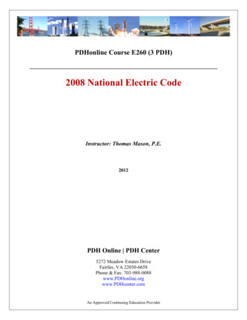
communications performance analyzerThe Agilent Technologies OmniBER 719communications performance analyzer offers asingle box field portable multi-rate SONET testerup to 2.5 Gb/s (OC-48). The analyzer is ideallysuited to installation, maintenance,commissioning, system verification andmanufacture of SONET transport networks andnetwork equipment.The latest enhancements to theOmniBER 719 analyzer include a choice ofinstrument variants for multi rate testing. Thisnew choice allows you to buy the SONET testconfiguration you need today and upgrade in thefuture as your testing needs move to higherSONET rates.Other enhancements added to the latestSide viewT-carrier Tx/Rx1310/1550 nm Txall optical ratesto 2.5 Gb/sSingle optical RxSONET moduleSTS-1, STS-3 Tx/RxDivided clock, frame pulseand error outputsFDD, HP-IBRS-232-C, LAN2
Summary ofcapabilitiesSummary of capabilityModelSONET ratesOptional T-carrier/PDH37719AOC-48, OC-12, OC3, OC-1STS-3, STS-1DS1, DS3, E1, E2, E337719BOC-12, OC3, OC-1STS-3, STS-1DS1, DS3, E1, E2, E337719COC-3, OC-1STS-3, STS-1DS1, DS3, E1, E2, E337719CSTS-3, STS-1DS1, DS3, E1, E2, E3OmniBER 719 include: Smartsetup autodiscover wizardsimultaneously displays all J1 traceidentifiers. Smartsetup lets you quickly and easilyexplore right down into the payload ofselected SONET tributaries. A telephone jack socket enables talk/listen onDS0 channels carried in higher rate signals. SONET-only configurations available. Electrical-only configuration available forSTS-3/STS-1 testing. E1 mapped into DS3. DS1 floating byte sync mapping. DS1 in-band and out-of-band loop codegeneration and monitor. New test patterns:Daly (55 octet), 1-in-8, 2-in-8.ContentsSummary of capabilities . 3Main features .4Other features .6SONET .7DS1/PDH/T-carrier (Option 013) . 14Jitter . 19ATM . 36General . 42Distributed Network Analyzer . 453
Main featuresSmartsetupLarge color displayNot only is the OmniBER 719analyzer rugged and portable, itseasy-to-use Smartsetup and SmartTests simplify and speed up theinstallation and maintenance ofSONET networks.The color VGA display on theOmniBER 719 analyzer operates insingle- or multi-window mode. Inmulti-window mode, four windowsare diplayed allowing simultaneousviewing of transmitter settings,receiver settings, graphical resultsand text results summary.The OmniBER 719 analyzer lets youstart testing with just two keypresses! With the analyzerconnected to any signal, simplypress the Smart Test key on thefront panel, select Smartsetup andthe instrument’s autodiscoverwizard automatically identifies theline rate and payload structure ofthe unknown input signal. ForSONET signals the analyzer alsoautomatically displays all of the J1trace identifiers, that is 48 J1identifiers in an OC-48 signal. Withthe signal structure now identifiedit’s a simple process, using thecursor control keys, to select achannel of interest and to exploreright down into the payload.Smart TestsThe front panel Smart Test keyoffers a simple shortcut to theextensive capabilities of theOmniBER 719 analyzer. The SmartTests are grouped together infunctional blocks so you don’t needto be an instrument ‘expert’ to gettests up and running quickly. Testcapability that is accessed with onlya couple of key presses include: Protection switch timemeasurementOptical power measurementLine frequency measurementError and alarm summaryresults.A VGA output is provided on theanalyzer’s front panel for connectionto VGA projector for trainingpurposes.Protection switch timemeasurementService disruption measurementcouldn’t be simpler than with theOmniBER 719 analyzer. Usingdedicated hardware, the analyzermeasures the length of the errorburst associated with a protectionswitch. Unlike the old method ofcorrelating bit errors with time, theunique implementation in theanalyzer (patent pending for DSn)is accurate to 50 ms with aresolution of 1 ms.SONET ring testingConfiguring SONET rings andverifying their functionality is acomplex and time-consumingprocess. Using the comprehensivethru mode capability of theOmniBER 719 analyzer can help tospeed up the task and ensure thatthe advantages of the SONET ringconfiguration will be delivered whenproblems arise on the live network.4
The three different thru modes ofoperation available are: Transparent: The SONETsignal is monitored and normalmeasurements made. The linesignal is passed throughunaltered without recalculationof BIPs.STS Payload overwrite:Select an STS SPE channel andoverwrite with an internallygenerated payload. BIPs arerecalculated and all other SPEsare retransmitted unaltered.Standard transmit test functionsare enabled so that it is possibleto add errors, alarms, pointeradjustments etc.VT payload overwrite: Selecta VT channel and overwrite withan internally generated payload.All other VTs are retransmittedunaltered. Standard transmittest functions are enabled sothat it is possible to add errors,alarms and pointeradjustments.Concatenated payloadsConcatenated payloads are vital forthe rapid and accurate testing ofhigh bandwidth paths before theyare brought into service. TheOmniBER 719 analyzer providesconcatenated payload testing at alllevels of a SONET signal. As well asproviding concatenated payloads atthe line rate e.g. OC-48c, theanalyzer lets you test SONETstructures containing concatenatedpayloads from lower levels of theSONET hierarchy e.g. STS-12ccarried in OC-48. See Figure 1 forthe full range of possibilities.Remote control formanufacturingEvery OmniBER 719 analyzer isshipped with a set of UniversalInstrument Drivers (UIDs) on CDROM. UIDs provide a suite ofgraphical function panels whichmake programming the analyzereasy and fast! There is no need toknow about SCPI commands – theSCPI commands are generatedautomatically by setting switches ona graphical function panel.UIDs are supported in the followingenvironments: HP VEELabviewLabWindows/CVIVisual BasicC and on the following operatingsystems: Windows 95Windows NTHP-UXSun Solaris.Remote control for remotein-service monitoringThe Distributed Network Analyzer(DNA) software (HP E4540A)allows control of anOmniBER 719 analyzer from aremote PC via modem or LAN.Changes made on the virtual frontpanel on the PC are seen in realtime at the remote site. Key pressesmade on the instrument at theremote site are seen in real time onthe PC – ideal for remotetroubleshooting by a centralizedexpert!For long-term monitoringapplications it is also possible to dialin to a remote OmniBER 719analyzer, download/update resultsand disconnect. Disconnect and reconnect at any time withoutinterrupting test progress.T-carrier and En testingThe T-carrier test module providescomprehensive test capability forDS1, DS3, E1, E2 and E3 interfaces.For DS3 testing FEAC codegeneration and monitor capability isincluded. At DS1 both in-band andout-of-band loop code generationand monitor is also available.The T-carrier test module alsoprovides mapped payload testingcapability for SONET testingOther supported functionalityincludes: Unframed, framed andstructured(mux/demux) testingError and alarm generation andmeasurement56 kb/s, n 56 kb/s, 64 kb/s andn 64 kb/s testingDS1 add/drop from DS3E1 add/drop from E2/E3DS1/DS3 and E1/E3 add/dropfrom SONETTelephone handset connectorfor talk/listen capability.Testing of E1 mapped into DS3 isalso available if required.5
Other features oftheSONET Troublescan automatically scansfor all possible error and alarmconditionsPayload offset testSONET error and alarmgeneration/detectionSONET tributary scanSONET pointer adjustments toGR-253Graphical pointer location graphAccess to SONET overheadOverhead sequence generationand captureText decode of APS messagesfor transmit and receiveOptical stress testDrop/insert of DCC channelsOptical power measurementLine frequency measurementLine frequency offsetChoice of clock reference:Internal, recovered, external 64kb/s, 1.5 Mb/s (BITS), 10 MHzPerformance analysis to ITU-TG.821, G.826, M.2101, M.2110,M.2120Graphical results storage.T-Carrier/PDH Troublescan automatically scansfor all possible error and alarmconditionsAlarm scanError and alarm generation/detectionDS1/DS3 thru modeChoice of clock reference:Internal, recovered, external 64kb/s, 1.5 Mb/s (BITS), 10 MHzLine frequency offsetSignaling bits generation/detectionPerformance analysis to ITU-TG.821, G.826, M.2100, M.2110,M.2120Graphical results storage.Jitter TestingThe OmniBER 719 can optionallyperform jitter generation andmeasurement at all installedinterface rates from 2.5 Gb/s to1.5 Mb/s. The jitter capability in theOmniBER 719 lets you ensure thatyour network equipment complieswith all relevant Bellcore jitterrecommendations. Jitter testapplications covered by theOmniBER 719 are: Output Jitter Measurement Auto Jitter Tolerance Auto Jitter Transfer Pointer Jitter Measurement Mapping Jitter MeasurementWhat’s more, the OmniBER 719meets the latest ITU-T 0.172recommendation for testequipment.Wander TestingWander measurements are used toverify the synchronization quality indigital networks. Using theOmniBER 719 it is possible tomeasure wander at all installedinterface rates from 2.5 Gb/s to1.5 Mb/s.To check network equipmentwander tolerance meets Bellcorerecommendations, wandergeneration can be performed at1.5 Mb/s, 2 Mb/s and also at allsynchronous rates from 52 Mb/s to2.5 Gb/s. Wander frequencies downto 10uHz and amplitudes up to57,600UI can be generated.As well as the standard Bellcoremasks, user definable jitter masksare included to let you specify theexact points you need to test yournetwork equipment.6
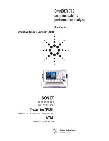
SONETFigure 1: Bellcore GR-253 mapping structure (SONET payload mapping)Optical interfaces37719A37719B37719CWavelengthOption 104Option 105Option 1061310 nm1550 nm1310/1550 nm1310 nm1550 nm1310/1550 nm1310 nm1550 nm1310/1550 nmRatesOC-48/12/3/1OC-12/3/1OC-3/1ConnectorsFC/PC (standard)SC (option 610)ST (option 611)Notes: Optical interfaces on the 37719A use a customerexchangeable connector system. On 37719B and 37719Cmodels, a fixed optical connector system is used (supportsremoval for cleaning).7
Optical transmittersThe following specifications cover both 1310 and 1550 nm transmitters unless otherwisestated.37719A37719B and 37719CNRZNRZ1280 to 1330 nmTypical: 1310 nm1280 to 1335 nmTypical: 1310 nm1550 nm1530 to 1570 nmTypical: 1550 nm1480 to 1580 nmTypical: 1550 nmPower0 to 3 dBmTypical: 1 dBm–3 to 2 dBmTypical: 0 dBmSpectral width Line codeWavelength1310 nm 0.3 nm at –3 dB1.0 nm at –20 dB 1.0 nm at –20 dBExtinction ratio 10 dBPulse maskMeets Bellcore GR-253-CORE and ITU-T G.957Fiber pigtailSingle modeLaser safetyClass 1 as defined by IEC825-1 and FDA 21 CFR,chapter 1, subchapter J.Optical receiver 10 dBSingle mode37719A37719B and 37719CLine codeNRZNRZWavelength1280 to 1335 nm and1500 to 1580 nm1200 to 1600 nmSensitivityOC-48: –28 dBmOC-12/3/1: –34 dBmOC-12: –28 dBmOC-3/1: –34 dBmMax input power–8 dBm–3 dBmFiber pigtailMulti-modeMulti-modeNotes:1. Sensitivity and maximum input power specifications are valid in the 0 to 40 C temperaturerange.2. Sensitivity and maximum input power specifications are measured at 10–10 error rateusing a 223 – 1 test pattern.3. 37719A: The optical receiver operates over the range 1200 to 1600 nm. Sensitivity andmaximum input power specifications are valid in defined wavelength ranges.8
Protected monitorpoint input52 Mb/s, 155 Mb/s and 622 Mb/s (not available on 37719C).Line code: NRZ.Level: Nominal 1 V peak-to-peak into 50 ohms.Connector: SMA female.Electrical linerates/interfacesSTS-3 (CMI), STS-1 (B3ZS)Input mode: Terminate or monitor mode.Monitor gain: 20 dB or 26 dBEqualization:STS-3: Automatic for cable loss up to 12 dB at half the bit rate.STS-1: Automatic covering range LO, x-connect and HI.STS-1 operating level:STS-1 HI: 1.1V peak nominal with cable equalization up to 450 ft.STS-1 900ft: As STS-1 HI with added cable equalization for 450ft to 900 ft.Connector: BNC, 75 ohm unbalanced.Option 620: WECO 560 connector replaces BNC.Clock referenceInternal: 0.5 ppm; stability: 3 ppm; Ageing: 1 ppm.Loop-timed: Clock recovered from receiver’s SONET input.External reference: BITS (1.5 Mb/s), 64 kb/s, 10 MHz.Connector: Bantam, 100 ohm balanced (BITS, 64 kb/s);BNC, 75 ohm unbalanced (10 MHz).Clock trigger51.840 MHz divided clock output.Connector: BNC, ECL to –2 V, ac coupled, 50 ohm.Trigger/error output60 msec (nominal) pulse on B1, B2, B3 error, Tx/Rx frame (TTL level, termination can be 75ohm or 10 kohm).Connector: BNC, 75 ohm unbalanced.Clock offset 999 ppm in 0.1 ppm steps; offset accuracy 0.02 ppmOffsets the transmitted OC/STS-n line frequency relative to the selected clock reference.SONET payload structureSee Figure 1 for details of SONET payload mapping.The foreground STS-n test signal can be mapped into any select channel in the SONET linesignal. Background channels can be set to the same as to the foreground or filled with anunequipped signal structure.Notes:1. Option 013 (T-carrier testing) is required for DS1/DS3/E1/E3/E4 mappings.2. OC-48 mappings only available on 37719A fitted with optical interface option (option 104, 105 or106).3. OC-12 mappings only available on 37719A or 37719B fitted with optical interface option (option104, 105 or 106).Payload offset 100 ppm in 1 ppm steps, linearity 0.5 ppm.The mapped DSn/En signal is offset with respect to the SPE in which it is carried.9
Payload test pattern29–1, 211–1, 215–1, 223–1 (inverted or non-inverted), all ones, all zeros, 1010, 1000, 16 bit userword.DS1 only: QRSS (220–1; 14 zero limited), Daly (55-octet) 1-in-8, 2-in-8.PDH/DSn drop/insertRequires option 013 (T-carrier testing).DS3, DS1, E3, E1 dropped from and/or inserted into OC-N/STS-N line signal (supported forasynchronous mappings only).SONET tributary scanAutomatically test BER on each SONET tributary for error free operation. Rx setup is used todetermine tributary structure and test pattern. (At OC-48/OC-12 the foreground STS-3 will bescanned).Alarms: Pattern loss.User selectable BER threshold: Off, 0, ³10–3,³10–6.,SONET error addData (whole frame)1, frame (A1,A2)1, CV-S (B1), CV-L (B2), REI-L (M0), REI-L (M1),CV-P (B3), REI-P (G1), STS IEC, CV-V (V5), REI-V (V5), bit1.Control: Single, error all, M.P x 10–n (where M.P 0.1 to 9.9 in 0.1 steps andn 3 to 9)2.N-in-T3, where N is the number of errors transmitted in time T,T 10 ms to 10000s in decade steps.N 0 to 640 (STS-1), 1920 (STS-3), 7680 (STS-12), 30720 (STS-48).1. No “error all” selection available.2. Max error rate depends on the error type.3. CV-L (B2) errors only.SONET alarm generationLOS, LOF, OOF, AIS-L, RDI-L, AIS-P, RDI-P, LOP-P, UNEQ-P, AIS-V, LOP-V, RDI-V, UNEQ-V, H4 LOM.Control: On/off.SONET pointer adjustmentsFrequency offset: Offset the SPE/VT relative to the line rate. In the SPE/VT pointer mode the87:3 sequence is generated. Frequency offset control ( 100 ppm in 0.1 ppm steps).Bellcore GR-253,ANSI T1.105.03 sequences: Initialisation sequence and cool down period1. Periodic single,2. Periodic burst,3. Periodic phase transient burst,4. Alternating single,5. Alternating double,6. Periodic with added,7. Periodic with cancelled.Programmable interval between regular adjustments.Regular: Interval between regular adjustments can be programmed as follows:10 ms T 100 ms in 10 ms steps100 ms T 1 s in 100 ms steps1 s, 2 s, 5 s or 10 sSingle burst: Incrementing burst, decrementing burst, alternating.Burst size: 1 to 10 adjustments (SPE). 1 to 5 adjustments (VT).Adjustments within the burst are separated by the minimum legal limit (4 frames/multiframes).New pointer: New pointer address transmitted with or without a NDF. SPE/VT payloadmoves to the user programmed address immediately.10
SONET overhead setupTOH: All bytes user settable except B1 B2, H1, H2 and H3. The size bits in H1 are settable.J0: User byte; 16 byte section trace message.S1: Clear text setup of synchronization status message.STS POH: All bytes user settable except B3.J1: 64 or 16 byte path trace message.C2: Clear text setup of signal label.VT POH: V5, J2, Z6, Z7 user settable.J2: User byte; 16 byte VT path trace message.V5 (VT signal label): Clear text setup of VT path signal label.SONET overhead monitorSOH, LOH, STS POH, VT POH all bytes (hex/binary)Text decodes provided for section trace (J0), synchronization status (S1),ASP/MSP messages (K1K2), STS and VT path trace messages (J1, J2),STS and VT signal labels (C2, V5).APS messagesClear text setup and decode of protection switching messages. Supports both linear (BellcoreGR-253) and ring (Bellcore GR-1230) messages.SONET overheadsequence generationSequence of up to 5 values transmitted in a selected overhead channel. The transmitduration for each value is user programmable in range 0 to 64000 frames.Overhead channel:SOH: A1-A2 (6 bytes), D1-D3 (3 bytes), J0, Z0 ,E1, F1,media dependent bytes (row 2 col 2; row 2, col 3; row 3 col 2; row 3, col 3).LOH: D4-D12 (9 bytes), K1K2 (2 bytes), S1, M0, M1, Z1, Z2, E2.POH: J1, C2, G1, F2, H4, Z3, Z4, N1.SONET overheadsequence captureA selected overhead channel can be selected for capture. The capture can be triggeredmanually or on a user-defined receive value. The first 16 different receive values including thetrigger are displayed along with the number of frames for which the value has persisted.Overhead channel:SOH: A1-A2 (6 bytes), D1-D3 (3 bytes), J0, Z0 , E1, F1,media dependent bytes (row 2 col 2; row 2, col 3; row 3 col 2; row 3, col 3).LOH: H1H2 (2bytes), D4-D12 (9 bytes), K1K2 (2 bytes), S1, M0, M1, Z1, Z2 E2POH: J1, C2, G1, F2, H4, Z3, Z4, N1.SONET overhead BER29–1 PRBS transmitted and analyzed in a single 64 kb/s overhead channel. Single bit errorscan be inserted in the transmitted test pattern.Overhead channel:SOH: D1-D3 (single byte), J0, Z0, E1, F1,media dependent bytes (row 2 col 2; row 2, col 3; row 3 col 2; row 3, col 3).LOH: D4-D12 (single byte), K1, K2, S1, M1, M0, E2.POH: J1, C2, G1, F2, H4, Z3, Z4, N1.Results: Error count, error ratio, error free seconds, % error free seconds,pattern loss seconds.11
Optical stress testPayload is overwritten with a block of zeros or ones after scrambling to stress timing recoverycircuits.Range:2 to 85 bytes – OC-1.2 to 259 bytes – OC-3.2 to 1042 bytes – OC-12.2 to 4174 bytes – OC-48.DCC add-dropD1-D3 (192 kb/s), D4-D12 (576 kb/s)Serial add-drop of DCC channels via RS-449 (15-pin D-type connector).SONET thru modeOC-48, OC-12, OC-3, OC-1, STS-3, STS-1 through mode:Transparent mode: Signal passes through unaltered. BIPs are not recalculated.Overhead overwrite: The test features associated with the TOH/POH can be enabled to alterone single or multi-byte overhead channel (ie, errors and alarms, overhead sequences, stress test,APS/MSP messages, DCC insert, overhead BER) In this mode the parity bytes are recalculated.STS payload overwrite: Overwrite a selected STS SPE channel with an internally generatedpayload. All other SPEs are retransmitted unaltered. All standard transmit test functions areenabled (errors and alarms, pointer adjustments, overhead sequences, stress test, overheadBER).VT payload overwrite: Overwrite a selected VT with an internally generated payload. Allother VTs and SPEs are retransmitted unaltered. All standard transmit test functions areenabled (errors and alarms; pointer adjustments).SONET alarm detectionLOS, OOF, LOF, AIS-L, RDI-L, LOP-P, AIS-P, RDI-P, H4-LOM, LOP-V, AIS-V, RDI-V, pattern loss, clockloss, K1/K2 change, power loss, pointer adjust.SONET error measurements Measurement control: Manual, single, timed start.Error: Frame (A1,A2), CV-S(B1), CV-L(B2), CV-LFE(REI-L), CV-P(B3), CV-PFE(REI-P),CV IEC (STS path IEC), CV-V(V5), CV-VFE(REI-V), bit.Basic results: Error count, error ratio, alarm seconds.Performance analysis: G.826, G.821, M.2100. M2101, M.2110, M.2120.Protection switch timesNote: Requires Option 013The ‘service disruption’ test measures protection switching time by measuring the duration ofthe error burst caused by a protection switching event (patent pending technique used with DSnsignals).Accuracy: 50ms.Results: Longest burst length, shortest burst length, last burst length.Resolution: 1ms.AlarmScanAutomatically identifies the payload structure then scans each STS/VT channel for alarms andBIP errors. Graphically displays the status of each STS/VT channel.Alarms:STS-SPE: LOP-P, AIS-P, RDI-P.VT : AIS-P, RDI-P, H4 LOM, LOP-V, AIS-V, RDI-V.BIP errors: B3 or V5 BIP-2 associated with each STS/VT channel.12
TroubleScanScans all possible error and alarm sources simultaneously. Non-zero error counts are displayedin large characters, up to a maximum of four different error counts.Pointer location graphGraphical display: Shows the variation with time of the STS SPE and VT pointer location. Upto four days of pointer location activity can be monitored.Implied SPE/VT offset: Calculated from the total ve and –ve pointer movements since startof the measurement period.Pointer resultsSPE and VT Justifications (pointer value, positive count, positive seconds, negative count,negative seconds, NDF seconds, missing NDF seconds, implied SPE/VT offset).Optical power measurement Accuracy: 2 dB; Range: –10 dBm to –30 dBm.Wavelength: 1310 nm or 1550 nm.Resolution: 0.1 dBm.Frequency measurementOC-48: Frequency displayed in kHz with a 0.1 kHz resolution. Offset in ppm/kHz OC-12: Frequency displayed in Hz with a 1 Hz resolution. Offset in ppm/Hz.Accuracy: 1 Hz (internal clock error1) frequency.1 See ‘clock reference’ for details on internal clock error.Stored measurementgraphics10 internal SMG stores (increases with floppy disc drive - number of stores limited onlyby free disc space).Bar chart: Results versus time periods with up to 1 second resolution.Alarm chart: Alarms versus time periods with up to 1 second resolution.Resolution: 1sec, 1min, 15min, 60minSONET bar graphs: Frame (A1A2), CV-S (B1), CV-L (B2), CV-LFE (REI-L), CV-P (B3),CV-LFE (REI-P), CV-IEC (STS path IEC), CV-V (V5), CV-VFE (REI-V), bit.SONET alarms: LOS, LOF, OOF, LOP-P, NDF, missing NDF, AIS-L, RDI-L, K1K2 change,AIS-P, RDI-P, H4 LOM, LOP-V, VT NDF, VT missing NDF,AIS-V, RDI-V, pattern sync loss, powerloss.13
DS1/PDH/T-carrier testing(Option 013)Adds T-carrier and En test capability. Testing can be performed directly at DSn/En physicalinterfaces or on SONET mapped payload signals.Line ratesDS1, DS3, E1, E2, E3Interfaces DS1: B8ZS/AMI; 100 ohm balanced (WECO Bantam).DS3: B3ZS; 75 ohm unbalanced (BNC1).E1: HDB3/AMI; 75 ohm unbalanced (BNC1), 120 ohm balanced (WECO Bantam).E2: HDB3; 75 ohm unbalanced (BNC1)E3: HDB3; 75 ohm unbalanced (BNC1).Input mode: Terminate or monitor mode.Monitor gain:DS1, E1/E2: 20, 26 dB or 30 dB.DS3, E3: 20 or 26 dB.Equalization:DS1: DSX-1,DS1-LO 0-655ft (ANSI T1.102-1993).DS3: DSX3, DS3-HI, DS3-900': 0-900ft (ANSI T1.102-1993).E1/E2: 6 dB at f/2.E3: 12 dB at f/2.DS1 operating level: DSX-1, DS1-LO.DS3 operating level: DS3-HI, DSX-3, DS3-900.E1 output level: ITU-T G.703.E2 output level: ITU-T G.703.E3 output level: ITU-T G.703.1 Option 620 replaces BNC with WECO 560 connector.14
Clock referencesInternal: 0.5ppm @ 25C [ 4.5 ppm (includes ageing, stability, setting accuracy)].DS1 only: 0.7ppm @ 25C [ 4.7 ppm (includes ageing, stability setting accuracy)].Loop-timed: Clock recovered from receiver.External reference: BITS (1.5 Mb/s), 64 kb/s, 10 MHz.Connector: Bantam, 100 ohm balanced (BITS, 64 kb/s);BNC, 75 ohm unbalanced (10 MHz).Line rate offset 100 ppm in 1ppm steps.Offsets the transmitted DSn/En line frequency relative to the selected clock reference.Frame formatFramed, structured (mux/demux), unframedFramingChannel structureDS1SF (D4), ESF, SLC-96(ANSI T1-403-1989,TR-TSY-000499, ITU-T G.704)56/64 kb/s, n 56/64 kb/sDS3M13 (ANSI T1-107-1995),C-bit (ANSI T1-107a-1990)DS1, 56/64 kb/s, n 64 kb/sOption 014: E1 (ITU-T G.747)E1PCM30, PCM30CRC,PCM31, PCM31CRC(ITU-T G.703, G.732, G.706)64 kb/s, n 64 kb/sE2ITU-T G.7422 Mb/s 64 kb/s, n 64 kb/sE3ITU-T G.7512/8 Mb/s, 64 kb/s, n 64 kb/sE41ITU-T G.7512/8/34 Mb/s, 64 kb/s, n 64 kb/s1 Supported as a mapped SONET payload (ie no physical E4 interfaces)Test patternPRBS: 29–1, 211–1, 215–1, QRSS (14 zero limit – DS1 only), 220–1, 223–1.Word: All 1s, all 0s, 1010, 1000, 16-bit word (frame aligned).DS1 only: 3-in-24, 1-in 8, 2-in-8, Daly (55 octet).Live traffic: Externally generated.The test pattern can be inserted/measured at the line rate or at any level within themultiplexing structure, inlcuding in a selected 64/56 kb/s or n 64/56 kb/s timeslot.15
Error addDS1: Bit, FAS (frame alignment signal), BPV/Code, CRC6, EXZ (excess zeros).DS3: Bit, FAS, MFAS (multi-frame alignment signal), FAS MFAS, BPV/Code, C-bit, P-bit,FEBE, EXZ.E1: Bit, FAS, code, CRC4, REBEE2/E3: Bit, FAS, code.E4: Bit, FAS (SONET payload – no interface provided).Control:SingleSelected error type transmitted when “single error” key is pressed.Rate1.0 10–3, 1.1 10–3, M.P 10–nn 4 to 9; M.P 1.0 to 9.9 in 0.1 steps)1BurstSingle burst of n-errors.EXZ: n 3 to 16.DS1 FAS: n 1 to 6DS3 FAS and MFAS: n 1 to 4En FAS: n 1 to 41Maximum error rate is 2.1 10–4 for:– DS1 CRC6 errors– DS3 FEBE, P-bit and C-bit errorsAlarm generationDS1: LOS, OOF, AIS, RAI (yellow).DS3: LOS, OOF, AIS, Idle, RAI (X-bit), FEAC codes (Loopback and alarm/status codes).E1: LOS, LOF, AIS, RAI, RAI (MF), CASMFL,minor alarm (via spare bits).E2/E3: LOS, LOF, AIS, RAI.E4: LOF, AIS, RAI (SONET payload – no interface).Control: On/off.Spare bits generationUser-selected value transmitted in spare bits of En frame.E4: FAS bits 14 to 16.E3: FAS bit 12.E2: FAS bit 12.E1: Si bits (international bits): Timeslot 0 bit1 in both FAS and NFAS frames.E1: E bits: CRC4 frames 13 and 15: timeslot bit 1.E1: Sa bit (national bits): NFAS timeslot bits 4 to 8.E1: Sa bit sequences: 8 bit sequence transmitted in any selected NFAS Sa bit.E1: CAS multiframe: MFAS timeslot bits 5,7 and 8.Signaling bitsgeneration/monitorDS1: Monitoring only. Displays signaling bits associated with all DS0 channels(ABCD format for ESF; AB format for SF (D4) and SLC-96).SLC-96 can display one of three states; 0,1 or alternating.E1: PCM30 and PCM30CRC frame formats.Transmit: User selected value transmitted in ABCD signal bits associated with all channels.Monitor: Simultaneously displays received ABCD signaling associated with all30 channels.16
FEAC codesDS3 C-bit frame format. Transmits and monitors loopback and alarm/status codes as per ANSIT1.107-1995.Transmit: Use-selected loopback or alarm/status code tranmitted for controlled duration.Loopback codes: A single burst of N loopback codes and M messages transmitted (where Nand M are selectable in the range 1 to 15).Alarm/status codes: Any ANSI T1.107-1995 message or any 0xxxxxx0 11111111 message maybe transmitted, either in a single burst (selectable in the range 1 to 15) or continuously.Monitor: Displays in decoded form the two most recently received FEAC messages (currentand previous messages.)DS1 loopcodesTransmits and monitors both in-band and out-of-band DS1 loopcodes.In-band: Line, payload, network, user (selectable in range 3 to 8 bits).Transmit: Selected code transmitted for 8 seconds (nominal).Monitor: Indicates the detection of a selected loop-up and loop-down code. Displays the lastvalid loopcode received.Out-of-band: Line, payload, network, universal user (11111111 0xxxxxx0).Transmit: Selected code transmitted either continuously or in a burst of n-messages (where nis selectable in range 1 to15).Monitor: Displays in decode form the two most recently received loopcodes (current andprevious).TroubleScanScans all possible error and alarm sources simultaneously. Non-zero error counts are displayedin large characters, up to a maximum of 4 different error counts.PDH alarm scanContinuously scans a received signal for alarms at the interface rate or within anysub-channel. Results presented graphically.Error and alarmmeasurementsMeasurement control: Manual, single, timed start.Errors:DS1: Bit, BPV/code, frame error, CRC6.DS3: Bit, BPV/code, frame error, P-bit, C-bit, FEBE.E1: Bit, code, frame error, CRC, REBE.E2/E3: Bit, code, frame error.E4: Bit, frame error (SONET payload – no interface).Alarms:DS1: LOS, pattern loss, AIS, OOF, multiframe loss, RAI (yellow), EXZ, idle.DS3: LOS, pattern loss, AIS, OOF, multiframe loss, RAI (x-bit), EXZ, idle.E1: LOS, pattern loss, AIS, LOF, RAI, RAI(MF), CASMFL.E2/E3: LOS, pattern loss, AIS, LOF, RAI.E4: LOS, pattern loss, AIS, LOF, RAI (SONET payload – no interface).Basic results: Error count, error ratio, alarm seconds.17
Performance analysisITU-T G.821 (bit), G.826, M.2100, M.2101, M.2110, M.2120.Additional measurementsLine frequency (Hz and ppm offset), delay (En signals only).Thru modeDS1 and DS3 only. Received signal is retransmitted either unchanged or with a selected errorrate injected across the entire DSn frame. All standard DSn received functions are available.Error rate: 1.1 10–3 to 1.0 10–9 (in 0.1 steps).DS1/E1 add-dropDS1 inserted and extracted from a DS3 signal. 100 ohm balanced (WECO Bantam).E1 inserted and extracted from a E2/E3/E4 signal. 75 ohm unbalanced (BNC).DS1, DS3, E1, E3 dropped from and/or inserted into an OC-N, STS-N line signal.Handset connectorSupports adding and dropping of a selected DS0 voice channel (carried in a DSn or En signal)to an external handset.Connector: RJ41
T-carrier/PDH: DS3, DS1, E1, E2, E3 (full mux/demux to DS0) ATM: DS1 to STM-16c /OC-48c OmniBER 719 communications performance analyzer Specification Effective from 1 January 2000. 2 communications performance analyzer The Agilent Technologies