Transcription
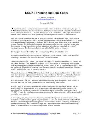
DS1/E1 Framing and Line CodesP. Michael Hendersonmike@michael-henderson.usNovember 11, 2002As communications becomes ever more important to both individuals and corporations, the speed andreliability of the lines that provide access to the Internet becomes critical. One of the most commonaccess services for business is T1 in North America and E1 in Europe/Asia. This paper describes howdata are carried in these T1/E1 lines, specifically the framing and line codes used in these circuits.Note that I use the term T1 but use DS1 in the title of the paper. I don’t know if there’s a real, officialdefinition of the difference between T1 and DS1 but I distinguish between the two as follows: a T1 signalis the actual electrical signal on the twisted pair. The DS1 signal is the digital signal to be transmittedover the T-carrier. The difference between the two comes about because there must be a certain onesdensity on the physical transmission media to maintain synchronization, which leads to a type ofencoding to do this. The discussion of this is covered in the LIU section of this paper.The European standard doesn’t have this nomenclature problem – it’s E1 all the time.When I talk about framing of the digital data, I’ll primarily use the term DS1 for the North Americantechnology. And when I talk about the line codes, I’ll use the term T1.I wrote this paper because I couldn’t find a good single source of information about DS1/E1 framing andline codes. There are a few books with the words “T1/E1 Networking” in their title but most seem tohave been written by network technicians whose primary interest in how to install and service T1/E1 linesand equipment. Discussion of the actual frame formats is generally superficial, ignoring how things areactually handled in the frame or multiplex structure.Alternately, there are the ANSI and ITU standards which contain the detailed data, albeit in abbreviatedform and without any explanation of why things were done the way they were. Additionally, the readeroften has to refer to a number of standards documents to understand how the whole system works.What was needed, I felt, was a document which explained things from an engineer’s point of view, insufficient detail that you could gain a relatively full understanding of the system.Writing a paper of this nature consumes quite a bit of time and energy, both for the research and theactual writing. As feedback to me, to let me know that people are actually reading this paper, I’dappreciate if you would send me an e-mail (at the address above) with nothing but a subject line of“T1/E1.” If you’d like to make comments, corrections, or offer suggestions, that would be appreciated ofcourse, but is not required.In writing the paper, I have to assume that you have a certain background in communications. Forexample, I do not discuss how speech is digitized into a 64 Kbps data stream, known as a DS0 in NorthAmerica. I assume that you know about protocols and understand the need for framing, and probably anumber of other things that I can’t think of right now. If you find that I assume too much knowledge,please let me know and I’ll add additional explanation in future revisions.P. Michael Henderson mike@michael-henderson.us Copyright 2002Page 1 of 21
November 11, 2002DS1/E1 Framing and Line CodesI begin by examining the North American digital hierarchy, focusing on the framing of the DS1 signal,including the usage of the framing bits and the so-called “robbed bits.” Next, I examine the Europeandigital hierarchy, with primary focus on the E1 signal. The European E1 framing is more regular than theNorth American framing and is much easier to understand. This simplicity shows up in this paper, withthe European section being shorter than the North American section.To be fair, I must note that the North American techniques were developed earlier than the Europeantechniques, and the Europeans learned from the missteps of the Americans. Additionally, the Europeantechniques were developed in standards bodies, since the telephone systems of the various Europeancountries had to interoperate. In these open forums the relative merits of various techniques were arguedand agreed. In the US, the AT&T network architects were able to implement without much concern forinteroperability since they were the first to develop digital networks and were only concerned withinterworking with themselves.But enough preface – let’s go examine the framing and line coding techniques.P. Michael Henderson mike@michael-henderson.us Copyright 2002Page 2 of 21
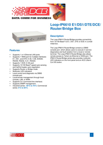
November 11, 2002DS1/E1 Framing and Line CodesNorth American Digital HierarchyDS1 FramingThe DS1 framing is the first level in the digital hierarchy above the actual voice channels. Speech iscoded according to the ITU G.711 specification, using μ-law encoding in North America, to give a64Kbps bit stream per channel. Specifically, the speech is coded eight bits per sample, with 8,000samples taken per second.The DS1 signal takes twenty-four of these DS0 channels and multiplexes them into a single bit stream,giving a rate of 1.536 Mbps. This multiplexing is octet (8 bits) oriented. That is, eight bits for eachchannel are contiguous. See Figure 1.123456Last four bitsof channel 24First two bitsof channel 28 bits for channel 17812 .45678192 bits, representing 24channels of 8 bits eachFigure 1: The multiplexing of 24 voice channels into a DS1 channel.But if the DS1 consisted of just a continuous stream of bits from the 24 voice channels, we wouldn’tknow how to identify which byte belonged to which channel, or for that matter, where the byteboundaries are. Put yourself into the position of the receiver. If you were receiving the string of bits,how would you determine what’s what? To find the start of this “frame” of 24 voice channels, we needsome type of framing.In HDLC, we use a special octet, the string of bits 0111 1110, as a framing character. Inside the frame,we suppress occurrences of this string with a technique known as “zero bit insertion.” And since HDLCframes can be variable length, we use another of these special characters as an ending flag to show wherethe frame ends. See Figure 2.P. Michael Henderson mike@michael-henderson.us Copyright 2002Page 3 of 21
November 11, 2002DS1/E1 Framing and Line CodesFlag Addr CTRL0x7ECRC(2 or 4octets)InformationFlag0x7EFigure 2: HDLC framing, showing the framing character, also knownas a flag.Today, bandwidth is cheap and we use bits freely. However, back in the late ‘50’s and early ‘60’s whendigital telephony was first being designed, bandwidth was expensive and scarce. Because of this, thesystem architects of the DS1 frame did not use a byte as a framing character – they used a bit. See Figure3 which shows the basic 193-bit DS1 frame. Since this 193-bit frame occurs 8,000 times per second, thenominal rate of a T1 line is 1.544 Mbps1. You might wonder how a single bit can be used as a framingcharacter, and that’s what we’ll explore next.F123456Last four bitsof channel 24First two bitsof channel 28 bits for channel 17812 .45678193 bits, representing 24channels of 8 bits each,plus a framing bit.Figure 3: DS1 framing showing the framing bit added to the 192 bitscarrying the 24 voice channels.If I’m sitting at the DS1 receiver and I correctly receive 193 bits, I know that one of those bits is theframing bit but I can’t tell which one it is. To find the framing bit, I must receive many frames and theframing bits must create a bit sequence which has a very low probability of occurring in any other bitposition. When the DS1 framing was first defined, the sequence of the framing bits was an alternatingpattern of ones and zeros.Since the sampling rate of speech is 8,000 samples per second, by Nyquist the maximum bandwidthwhich can be sampled is 4 Khz. To prevent aliasing, the G.711 codec has an analog filter whichattenuates signals above 3400 Hz, requiring at least 14 dB of attenuation at 4KHz. Because of this, it isextremely unlikely that the digitized speech contains a significant 4KHz component. And if you work itout, a voice channel can only have alternating bits in the digitized data stream if the digital data represents1ANSI T1.102 of 1993 calls for a tolerance of /-32 parts per million on the 1.544 Mbps signal.P. Michael Henderson mike@michael-henderson.us Copyright 2002Page 4 of 21
November 11, 2002DS1/E1 Framing and Line Codesa 4KHz signal2. Therefore, a bit alternating between zero and one has a low probability of occurring inany bit position except the framing bit.So how do we find the framing bit? There are a number of more efficient techniques, but the brute forcetechnique is to receive a sequence of bits, and select one bit position as the candidate position for theframing bit. Then, look ahead 193 bits and see if that bit is opposite to the first bit chosen. If not, selectthe next bit and try again. But it the bit is opposite, look ahead another 193 bits and see if that bit changespolarity back to the first bit. If not, select the next bit and try again. Eventually, you’ll find the framingbit, and with that, you’ll be able to decode each of the speech channels correctly. Once you find theframing bit, continue to monitor it to make sure that it continues to alternate. If it stops alternating, itmeans that you no longer have frame synchronization and you need to go back and find the framing bitagain.So how long does it take to establish framing? Assuming no bit errors in the input data stream, for thisbrute force type of bit framing, the average (or expected) time to achieve framing is given by theequation3:Frame time N 2 Nbit times2Where N is the number of bits in the frame, including the framing bit. For a DS1 frame of 193 bits, theexpected framing time is 37,346 bits, or 24.188 ms. The maximum is twice this, or 48.25 ms.,representing the time it would take to examine each of the 193 bits in sequence (you start at the bit justafter the framing bit and have to run through all the bits in the frame). It’s important that the framing timebe fast enough that people do not hear a loss of speech if synchronization is lost on a T1 line. That is, theline should be able to detect loss of synchronization and resynchronize fast enough that a person does nothear anything unusual. Special techniques have been developed to quickly recover from loss ofsynchronization based on the fact that loss of sync is usually a slip of a small number of bits.With this framing, we can quickly find frames and obtain the payload (speech) information. But there’ssome additional information that needs to be communicated about a telephone call, and that’s the “callprogress” information. For example, you’re sitting at the DS1 receiver in a telephone central office, allframed up, taking bytes and putting them in the right DS0 channels. But telephone calls are notpermanent – they are set up and then torn down. How can you know when a call is coming in on a DS0or when the call is finished?Today, this is accomplished by communications in a separate channel using a technology known asSignaling System 7. This technique is known as “common channel signaling” (CCS). But back in theearly days of the telephone network, signaling was done in-band, known as “channel associatedsignaling” (CAS)4.2This, of course, is also the reason we use a 1004Hz test tone instead of a 1000Hz tone. If we used a 1000Hz toneand it was synchronized with the sample clock (exactly 1/8 of the 8,000Hz sampling rate), the same eight sampleswould be sent over and over. This would not do a good job of testing the codec or the channel.3The derivation of this equation is given in Bellamy. See the Bibliography.4It was this in-band signaling which allowed the “phone phreaks” to steal long distance. They would put certaintones on the line which kept the system from billing for a call. Common channel signaling stopped this. But whowould want to risk stealing long distance now, when it’s almost free?P. Michael Henderson mike@michael-henderson.us Copyright 2002Page 5 of 21
November 11, 2002DS1/E1 Framing and Line CodesSignaling does not require a great many bits, and if you’re going to preempt some of the information bitsfor signaling, you want to take as few as possible. The way the designers obtained bits for signaling isthat they stole (usually called “robbed”) the low order bit from a speech byte, every six speech samples.What impact might this have on the speech? The byte with the robbed bit is sent to the DS0 channel,where it’s used to generate the speech sound. Fifty percent of the time, even though the network uses thelow order bit, it is not changed. The other fifty percent of the time, the bit is changed but the change insound is minimal – the sound is changed to the next quantization point (up or down) but the actualdifference in sound is not great enough to cause noticeable distortion for the listener.This robbed bit could be used in a variety of ways. Most logically, it could create a low speed channelwithin which signaling messages could be sent. But this is not the way signaling was done in the earlydays of the digital network. What the designers did was to create a two bit message (later extended tofour bits), called the A and B bits. With the A/B bits, four messages could be sent – {00, 01, 10, 11}.Additionally, they could pulse the bits (called “wink”) to send additional signals5.In light of today’s technology, this signaling technique seems extremely limited while also addingcomplex framing conditions (to be explained shortly). But remember how this developed. T1 lines wereinitially used between analog central offices, simply to replace the multiple analog circuits which hadbeen used previously. The signaling had to be something which would interface with the analog switchesalready installed and operational in the central offices. Thus this “kluge” of the A/B bits.So how did the designers set up the framing so that they could find these A/B bits? They created aconcept called a “superframe” which consists of twelve of the 193 bit frames. So now, in addition tofinding the start of a frame, the receiver has to find the start of the superframe. How is this done?We still need a pattern of alternating zeros and ones because this pattern has a low probability ofoccurring in the speech samples. Suppose that we put this alternating pattern on every other frameinstead of each frame. So the framing bit on frame one is a 1, the framing bit on frame three is a 0, theframing bit on frame five is a 1, etc. We can certainly find this pattern because it’s just as if we increasedthe frame size to 386 bits instead of 193 bits. It will take longer to obtain synchronization (worse case of96.5 ms with the brute force technique) but superior techniques have been developed which obtainedsynchronization faster than the brute force technique described earlier.And once we find synchronization on the 386 bit frames, we need to find the start of the 12 frame (193 bitframe) superframe. This is done by putting a unique sequence of bits in the other six framing bits withinthe superframe. This sequence is {0, 0, 1, 1, 1, 0}. Now we can obtain frame synchronization andsuperframe synchronization. See Table 1 which shows how the framing bits are allocated.5Later, tones were used in conjunction with the A/B bits. For example, MF tones are used to send dialed digits afterthe receiver signals through the A/B bits that it is ready to receive.P. Michael Henderson mike@michael-henderson.us Copyright 2002Page 6 of 21
November 11, 2002Framenumber123456789101112DS1/E1 Framing and Line CodesBit numberFramealignmentbit valueSuperframealignmentbit 0021230Table 1: Superframe framing and signaling bits.Signaling bitvalue in loworder databitsABAnd within this superframe, we’re interested in the sixth frame and the twelfth frame. Each of these two193 bit frames contains 24 bytes of digital speech, one byte for each channel. Each of these bytes has thelast (lowest order) bit stolen to be used for signaling. The low order bits in the sixth frame are the A bitsand the low order bits in the twelfth frame are the B bits. Note that this affects every channel on the T1circuit. Both the sixth and twelfth frames contain bytes for all 24 channels and all have the lower orderbit stolen. So every channel on any T1 which uses robbed bit signaling will have “corruption” in everysixth speech sample.More information on how the A/B bits are used for signaling can be found in ANSI T1.403.02-1999.The superframe technique was a good solution for use between central offices. The telephone companiescould monitor the lines on each end and determine the quality of the lines. But when T1s started beingused for provisioning service to customers, problems were encountered, primarily in monitoring thequality of the line. To solve this problem, another framing technique, known as “Extended Superframe”(ESF) was developed.ESF groups 24 frames (193 bit frames) together to form the extended superframe, so now we have 24“framing bits” that we can use for a variety of purposes. Remember that in the superframe, we used six ofthe twelve framing bits for individual frame alignment, and six for superframe alignment. A morecomplex allocation of bits is used for ESF. Of the 24 bits, six are allocated for the “frame alignmentsignal” (FAS), six bits are allocated to CRC, and twelve bits are allocated to a data link channel.The frame alignment bits occur every fourth frame, starting with the fourth frame and consist of the bits{0, 0, 1, 0, 1, 1}. Note that the framing pattern is no longer an alternating {0, 1} pattern. While thispattern could be duplicated in the data portion of the frame, it is very unlikely that both the FAS and theCRC could be duplicated, making the frame synchronization even more robust than previous techniques6.6Since there are six CRC bits, the probability of a match is only one in 64 making the probability of a match of boththe FAS and the CRC of 1 out of 642 for random data.P. Michael Henderson mike@michael-henderson.us Copyright 2002Page 7 of 21
November 11, 2002DS1/E1 Framing and Line CodesClever synchronization techniques are required now because the framing bits occur every 772 bits,leading to a long synchronization acquisition time if the brute force technique were used (almost 200 msworse case).The CRC is calculated on the extended superframe block with the 24 framing bits assumed to be set to 1.The result of the CRC calculation is then put into the CRC locations in the next ESF block7. Thus, theframing bits are not checked for errors by the CRC – only the information bits.The data channel is open for any use but is usually used for system monitoring traffic. That is, HDLCframes are communicated between the central office and the T1 terminating equipment for control, testingand status monitoring purposes. See Table 2 which shows how these bits are 2021222324Bit numberFrameAlignmentSignalbit 46M1244391Table 2: Extended Superframe framing, data link and CRC bits.Signaling bitvalue in loworder databitsABCDNote that we now have a set of four “robbed bits” designated as {A, B, C, D}. This allows us to havesixteen signaling states instead of the four possible with just {A, B} bits. The four state robbed bits canbe used in a degenerate form as {A, B, A, B} which is the same as the superframe situation.7Details of how the CRC is calculated can be found in ANSI T1.107-1995.P. Michael Henderson mike@michael-henderson.us Copyright 2002Page 8 of 21
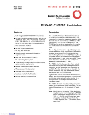
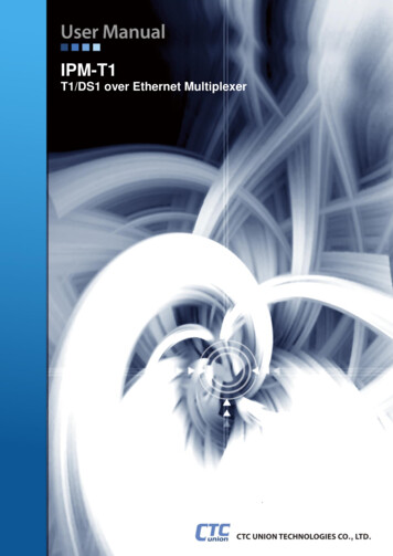
November 11, 2002DS1/E1 Framing and Line CodesEuropean Digital HierarchyE1 FramingThe E1 framing is the first level in the digital hierarchy above the actual voice channels. Speech is codedaccording to the ITU G.711 specification, using A-law encoding, to give a 64Kbps bit stream per channel.Specifically, the speech is coded eight bits per sample, with 8,000 samples taken per second.The E1 frame carries 30 voice channels in a 256-bit frame. Since 30 channels only requires 240 bits, 16bits are available for framing, signaling, error checking and supervisory communications. These extra 16bits are divided into two groups of 8 bits each. The first 8 of these 16 “extra” bits are located in the first 8bit positions of the 256 bit frame, while the second eight bits are located in bit positions 129 through 136(with the first bit numbered as 1). If we take the 256 bits 8 bits at a time, and call each 8 bits a channel,we have 32 channels in the frame. In the standard, these channels are numbered from 0 (zero) to 31. Thefirst overhead octet represents channel zero, therefore, and is known as the framing channel. The nextoverhead octet represents channel 16 and is known as the signaling channel. The remaining channels areknown as message channels. See Figure 4 which shows the basic E1 frame. Note that each numberedblock represents 8 bits.Framingchannel0Signalingchannel1234 .161718 .2728293031256 bits, representing 32channels of 8 bits each two overhead channels and30 message channelsFigure 4: The basic E1 frame of 256 bits, showing the framing channeland the signaling channel.Sixteen of these 256 bit frames are organized into a multiframe, as shown in Figure 5. Now, let’sexamine how the framing is done so that we can find the start of the frame and the multiframe.P. Michael Henderson mike@michael-henderson.us Copyright 2002Page 9 of 21
November 11, 2002DS1/E1 Framing and Line CodesSignalingchannelFramingchannelFrame 0234 .161718 .27282930311234 .161718 .2728293031Frame 2 FAS 1234 .161718 .2728293031Frame 1FAS 10 1234 .161718 .2728293031Frame 14 FAS 1234 .161718 .2728293031234 .161718 .2728293031Frame 13Frame 15001Figure 5: The E1 multiframe of 16 frames. Note that the framealignment signal occurs every other frame.The bits of the first octet of each frame are allocated either to the frame alignment signal (FAS) or to amessage link for operations, maintenance, or performance monitoring. The use of the first octetalternates. The first octet on one frame will be the FAS, while the first octet on the next frame will be forthe administrative channel. This means that, for framing purposes, the frame length is 512 bits.The bits of the octets are set as follows (Table 3):Frame descriptionFrame containingthe frame alignmentsignal (FAS)Frame notcontaining the framealignment signal(non-FAS or NFAS)123Bit number45678Si0011011Si1ASa4Sa5Sa6Sa7Sa8Table 3: Bit assignments in the framing channel of an E1 multiframe.The first bit of each octet of the framing channel may be used for a CRC-4 to further verify multiframealignment. This is described later. The frame alignment signal is {0, 0, 1, 1, 0, 1, 1}. In the octets notcontaining the FAS (the NFAS), the second bit is fixed to 1 to guarantee that the pattern in this octet cannever be the same as the FAS. I won’t describe the rest of the bits in the non-FAS octet except to say thatthey are used for remote alarm indication (A), administrative purposes, and synchronization status. SeeG.704 for more details.P. Michael Henderson mike@michael-henderson.us Copyright 2002Page 10 of 21
November 11, 2002DS1/E1 Framing and Line CodesHere we have seven bits of framing for each “frame”, and for framing purposes, a frame is 512 bits. Theequation8 for the average time to achieve framing isFrame time N2Nbit times L2(2 1) 2Here, N 512, and L 7. The average time to achieve framing is 1288 bit times, or about 0.63 ms. Notethat this is the average time. The maximum time will be twice the average. The reason this is so muchfaster than DS1 framing is that there’s a higher percentage of framing bits. Note also, that if yousubstitute the DS1 values of N 193 and L 1 into this equation, you will not get the same answer as givenin the DS1 section. This is because the DS1 framing consists of alternating bits while the E1 framing bitsare fixed. With alternating bits the framing time is longer, here about twice as long.When the first bit of each frame is not used for CRC-4 framing, it is normally set to 1. When the first bitof each frame is used for CRC-4, the multiframe is separated into two sub multiframes (SMF) of eightframes each. The first bit of the FAS in each SMF is used for the CRC-4 while the first bit of all eightnon-FAS octets are used to carry a framing pattern plus a backward error indicator. This is shown inTable 4.SubmultiframenumberIMultiframeIIFramenumberBit 1 of 3EC4ETable 4: Meaning of the first bit of each frame, when the bit isused for CRC-4.The CRC-4 is calculated over the submultiframe (2048 bits), with the CRC bits set to 0 for thecalculation. The result of the CRC-4 calculation is then placed in the C1-C4 bit locations of the nextsubmultiframe. The CRC-4 alignment signal is {0, 0, 1, 0, 1, 1}. The E bits are used to indicate whethersubmultiframes were received with errors. Normally, the E bits will be 1, but are set to 0 to indicate a8This equation is also derived in Bellamy.P. Michael Henderson mike@michael-henderson.us Copyright 2002Page 11 of 21
November 11, 2002DS1/E1 Framing and Line Codessubmultiframe with a CRC error (the first E bit applies to the first submultiframe of a multiframe, whilethe second E bit applies to the second submultiframe).Signaling in E1 is accomplished through the signaling channel (channel 16). This channel can carrysignaling similar to the robbed bit signaling for DS1, or can carry HDLC (LAP-D) frames for higher-leveltype signaling. If ABCD bit type signaling is used, the first octet in channel 16 of the multiframe willcontain {0, 0, 0, 0, x, y, x, x9}. The remaining octets of channel 16 (fifteen octets since there are total of16 frames in a multiframe) will contain {A, B, C, D, A, B, C, D}. That is, each octet will contain thesignaling for two channels. The first four bits will contain the signaling for the channel with the samenumber as the frame number. So the first four bits in the channel 16 octet of frame 1 will contain thesignaling for voice channel 1 of the 30 voice channels.The second four bits in that octet will contain the signaling for the voice channel 15 channels higher. Sothe second four bits in the channel 16 octet in frame 1 will contain the signaling for voice channel 16(which is carried in slot number 17 of the frame). Thus, when we get to frame 15 (the last frame of themultiframe), the signaling octet will contain signaling for voice channels 15 and 30. Thus, eachmultiframe contains signaling for each channel. The difference from DS1 is that no bits are taken fromthe message channels so each message channel is a clear channel 64Kbps (no robbed bits). Signaling inthis channel is described in the Q.400 series of ITU recommendations.9Where x don’t care and y remote alarm indication.P. Michael Henderson mike@michael-henderson.us Copyright 2002Page 12 of 21
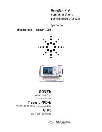
November 11, 2002DS1/E1 Framing and Line CodesLine CodesThe basic technique for sending information over a copper wire is to apply a voltage in a certain patternwhich can be detected and interpreted at the other end. Of course, like most things in life, the devil is inthe details. I’m going to “selectively ignore” some of the details in this discussion and just talk about thevoltage patterns which are used on the wire to communicate T1 and E1 signals.The following discussion is “high level” and only addresses why certain things are done. I won’t discussthe specific voltage levels, line impedances, etc. Those details can be found in the appropriate standardsdocuments.The basic technique for communicating over copper wire is to use voltage pulses. For example, a positivegoing voltage pulse could be used to represent a logic 1 and a negative going voltage pulse could be usedto represent a logic 0. Such a signal is called a non-return to zero (NRZ) signal. If a non-zero voltage isused for a logic 1 (for example) and zero voltage is used for logic 0, the signal is called a return to zero(RZ) signal. If the voltage level is one sided (only a positive voltage or only a negative voltage), aproblem known as DC balance is encountered. Because of this, one-sided RZ signaling is not commonlyused in communications.1000101110111NRZ10001RZFigure 6:An example of a non-return to zero (NRZ) and a return to zero (RZ)signal.In either case, if the pulse is a square wave with a 100% duty cycle, the frequency spectrum on the wirewill be the familiar (sin x)/x function, shown below, the plot of which is shown in Figure 7.P. Michael Henderson mike@michael-henderson.us Copyright 2002Page 13 of 21
November 11, 2002F ( ) TDS1/E1 Framing and Line Codessin( T / 2) T / 2where: ω 2πfT pulse timeThis equation is obtained by taking the Fourier integral10 for a single square wave pulse centered at t 0and extending from -T/2 to T/2. The power spectrum is obtained by taking the square of the modulus andmultiplying it by a scaling factor. See Figure 7.1/T2/T3/TFrequency 4/TFigure 7: The plot of F ( ) 2 (1/ T ) , the power spectral density of thepulses represented by F ( ) Tsin( T / 2). T / 2There are several things to note in this figure. First, note that the energy goes to zero periodically, withthe period related to the duration of the pulse. Second, most of the energy is in the frequency band below1/T frequency. Finally, since the pulse is a square wave, the frequencies will extend to infinity.Now, let’s talk about the real world. First, the frequencies can’t extend to infinity because the attenuationon copper wire increases significantly as the frequency increases. So the pulse will not be square – it willbe rounded off, approaching the shape shown below.10The Fourier integral isF ( )
Note that I use the term T1 but use DS1 in the title of the paper. I don't know if there's a real, official definition of the difference between T1 and DS1 but I distinguish between the two as follows: a T1 signal is the actual electrical signal on the twisted pair. The DS1 signal is the digital signal to be transmitted over the T-carrier.