Transcription
Air Conditioning Control SystemCentralized ControllerEW-50A/EW-50EInstallation and Instructions ManualContents1. Safety precautions. 21-1. General precautions.21-2. Precautions for unit installation.31-3. Precautions for electrical wiring.31-4. Precautions for relocating or repairing the unit.41-5. Additional precautions.42. Introduction. 62-1. Part names.63. Package contents. 84. Specifications. 94-1. Product specifications.94-2. External dimensions.105. Installation.115-1. Items not included.125-2. Items sold separately.125-3. Installation space.135-4. Installation procedures.146. Wiring connections. 17Safety notes are marked withWARNINGorCAUTION, depending on the severityof possible consequences that may resultwhen the instructions are not followedexactly as stated.Proper installation is important for yoursafety and proper functioning of the units.Thoroughly read the following safetyprecautions prior to installation.6-1. Removing/reinstalling the service cover.176-2. Connecting AC power cables and M-NET transmissioncables.196-3. Connecting the LAN cable.216-4. Confirming the LAN transmission delay time.217. Initial settings. 237-1. Logging in to the Web Browser for Initial Settings.237-2. Initial settings on the Web browser.237-3. Quick IP address (LAN1) setting.247-4. Network settings on the Web browser.258. Test run. 268-1. Collective operation ON/OFF.269. External input/output. 279-1. External signal input/output function.279-2. Pulse signal input function.2910. Maintenance. 3010-1. Inspection and maintenance.3010-2. Back up/import settings data.3110-3. Software update.3310-4. Software information.36Before installing the controller, please read this Installation Manual carefully to ensure proper operation.Retain this manual for future reference.
1. Safety precautions Thoroughly read the following safety precautions prior to installation. Observe these precautions carefully to ensure safety. After reading this manual, pass the manual on to the end user to retain for futurereference. The user should keep this manual for future reference and refer to it as necessary. Thismanual should be made available to those who repair or relocate the units. Make surethat the manual is passed on to any future air conditioning system user. All electrical work must be performed by qualified personnel.: indicates a hazardous situation which, if not avoided, could result indeath or serious injury.: indicates a hazardous situation which, if not avoided, could result inminor or moderate injury.: addresses practices not related to personal injury, such as productand/or property damage.1-1. General precautionsDo not install the controller in areas where large amounts of oil, steam, organic solvents,or corrosive gases (such as ammonia, sulfuric compounds, or acids), or areas whereacidic/alkaline solutions or special chemical sprays are used frequently. These substancesmay significantly reduce the performance and corrode the internal parts, resulting inelectric shock, malfunction, smoke, or fire.To reduce the risk of injury, electric shock, or fire, do not alter or modify the controller.To reduce the risk of electric shock, malfunction, smoke, or fire, do not touch the electricalparts or USB memory with wet fingers.To reduce the risk of injury or electric shock, before spraying a chemical around thecontroller, stop the operation and cover the controller.To reduce the risk of burns, do not touch the electrical parts with bare hands during andimmediately after operation.To reduce the risk of injury, keep children away while installing, inspecting, or repairing thecontroller.Test runs, inspection, and service must be performed by qualified personnel in accordancewith this manual. Incorrect use may result in injury, electric shock, malfunction, or fire.If you notice any abnormality, stop the operation and turn off the controller. Continuing theoperation may result in electric shock, malfunction, or fire.Properly install all required covers to keep moisture and dust out of the controller. Dustaccumulation and the presence of water may result in electric shock, smoke, or fire.To reduce the risk of frostbite, burns, injury, or electric shock, keep the equipment out ofthe reach of children.WT07936X032
To reduce the risk of fire or explosion, do not place flammable materials or use flammablesprays around the controller.To reduce the risk of electric shock or malfunction, do not touch the switches or buttonswith a sharp object.To reduce the risk of injury, electric shock, or malfunction, avoid contact with the sharpedges of certain parts.To reduce the risk of injury, wear protective gear when working on the controller.Wear protective gear when working on the controller. High-voltage parts pose a risk ofelectric shock, and high-temperature parts pose a risk of burns.1-2. Precautions for unit installationDo not install the controller where there is a risk of flammable gas leaks. If flammable gasaccumulates around the controller, it may ignite and cause a fire or explosion.Properly dispose of the packing materials. Plastic bags pose a suffocation hazard tochildren.Take appropriate safety measures against earthquakes to prevent the controller fromcausing injury.To prevent injury, install the controller on a flat surface strong enough to support itsweight.To reduce the risk of short circuits, current leakage, electric shock, malfunction, smoke, orfire, do not install the controller in a place exposed to water or in a condensingenvironment.The controller must be installed by qualified personnel according to the instructionsdetailed in this manual. Improper installation may result in electric shock or fire.1-3. Precautions for electrical wiringTo reduce the risk of malfunction, smoke, fire, or damage to the controller, do not connectthe power cable to the signal terminal block.To reduce the risk of malfunction, smoke, fire, or damage to the controller, do not apply apower supply voltage in excess of that specified.Properly secure the cables in place and provide adequate slack in the cables so as not tostress the terminals. Improperly connected cables may break, overheat, and cause smokeor fire.To reduce the risk of injury or electric shock, switch off the main power before performingelectrical work.WT07936X033
Electrical work must be performed by qualified personnel in accordance with localregulations and the instructions provided in this manual. Only use specified cables anddedicated circuits. Inadequate power source capacity or improper electrical work willresult in electric shock, malfunction, or fire.To reduce the risk of electric shock, install an overcurrent breaker and an earth leakagebreaker on the power supply. To reduce the risk of electric shock, smoke, or fire, install anovercurrent breaker for each controller.Only use properly rated breakers (earth leakage breaker, local switch switch fuse thatmeets local electrical codes , moulded case circuit breaker, or overcurrent breaker). Theuse of improperly rated breakers or the substitution of fuses with steel or copper wire mayresult in electric shock, malfunction, smoke, or fire.To reduce the risk of current leakage, overheating, smoke, or fire, use properly ratedcables with adequate current carrying capacity.Proper grounding must be provided by qualified personnel. Do not connect the protectiveground wire to a gas pipe, water pipe, lightning rod, or telephone wire. Improper groundingmay result in electric shock, smoke, fire, or malfunction due to electrical noiseinterference.To reduce the risk of short circuits, electric shock, or malfunction, keep wire pieces andsheath shavings out of the terminal block.To reduce the risk of short circuits, current leakage, electric shock, or malfunction, keepthe cables out of contact with controller edges.To reduce the risk of electric shock, malfunction, or fire, seal the gap between the cableand the end of the conduit tube with putty.To reduce the risk of injury, do not touch the burrs of the knockout holes.1-4. Precautions for relocating or repairing the unitThe controller must be repaired or moved only by qualified personnel. Do not disassembleor modify the controller. Improper installation or repair may result in injury, electric shock,or fire.To reduce the risk of short circuits, electric shock, malfunction, or fire, do not touch thecircuit board with tools or with your hands, and do not allow dust to accumulate on thecircuit board.1-5. Additional precautionsTo avoid damage to the controller, use appropriate tools to install, inspect, or repair thecontroller.To prevent unauthorized access, always use a security device such as a VPN router whenconnecting to the Internet.WT07936X034
Take appropriate measures against electrical noise interference when installing thecontroller in hospitals or radio communication facilities. Inverter, high-frequency medical,or wireless communication equipment as well as power generators may cause the airconditioning system to malfunction. The air conditioning system may also adversely affectthe operation of these types of equipment by creating electrical noise.To avoid malfunction, do not bundle power cables and signal cables together or placethem in the same metallic conduit.To avoid damage to the controller, do not overtighten the screws.To avoid deformation and malfunction, do not install the controller in direct sunlight orwhere the ambient temperature may exceed 55 C (131 F) or drop below -10 C (14 F).This appliance is not intended for use by persons (including children) with reducedphysical, sensory or mental capabilities, or lack of experience and knowledge, unless theyhave been given supervision or instruction concerning use of the appliance by a personresponsible for their safety. Children should be supervised to ensure that they do not playwith the appliance.WT07936X035
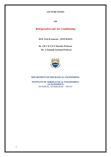
2. IntroductionEW-50A/EW-50E is a total management system.Any connected air conditioning systems can be operated or monitored on the Web browser. EW-50A/EW-50E canalso be used as an expansion controller of AE-200A/AE-200E.By connecting AE-200A/AE-200E, up to 200 indoor units and other equipment can be controlled.Hereafter, AE-200A and AE-200E, unless otherwise specified, will be called “AE-200.”Hereafter, AE-50A and AE-50E, unless otherwise specified, will be called “AE-50.”Hereafter, EW-50A and EW-50E, unless otherwise specified, will be called “EW-50.”Note: A PC is required to monitor and operate the air conditioning units.Note: The required licenses vary, depending on the functions to be used. Consult your dealer.Note: For how to use the Web browser, refer to the Instruction Book (Integrated Centralized Control Web).2-1. Part namesUSB port(unused)ON/OFFPowerStatusPush switch ON/OFFPush switch ResetLINK/ACT2LINK/ACT1Service coverItemPowerLEDON/OFFStatusDescriptionLit in greenPower ONUnlitPower OFFLit in greenOne or more air conditioning units are ON. *1Blink in greenOne or more air conditioning units or other related equipmentare in error.UnlitAll air conditioning units are OFF. *1Blink in orangeStartup errorBlink in blueSoftware update in progressBlink in pinkSoftware update failedLINK/ACT1Blink in orangeData transmission in progress (LAN1)LINK/ACT2Blink in orangeBACnet data transmission in progress (LAN2)ON/OFFUsed to turn the connected air conditioning units and the otherrelated equipment ON and OFF all at once.ResetUsed to reboot the EW-50. (This will not affect the operationstatus of the air conditioning units.)Push switchUSB portUnused*1 The operation status of the other equipment are excluded.WT07936X036
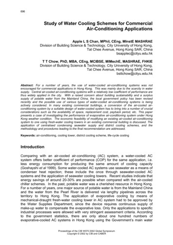
** Back side with the service cover TB3TB1GroundItemDescriptionSW1IP addresses can be easily set with SW1. Refer to section 7-3 “Quick IPaddress (LAN1) setting” for details.LAN1Connects to other units of equipment over the LAN via a HUB.LAN2Connects to the Building Management System over the LAN (BACnet ) via aHUB.CN7 (Pulse Input) *1Connects to metering devices using the supplied connector.CN6UnusedCN4UnusedCN5 (External I/O) *1Connects to an external input/output adapter PAC-YG10HA-E.(When connecting an external input/output adapter PAC-YG10HA-E, cut outthe knockout hole.)Connects to the M-NET power jumper to supply power (default).CN21 (M-NET power jumper)** If another system controller is connected to the same M-NET system and the powerconsumption coefficient is 1.5 or above, disconnect the M-NET power jumper to supplypower from the separately-sold power supply unit.TB3 (M-NET A, B, S) (M3.5)M-NET transmission terminal blockConnects to M-NET transmission cables from the outdoor unit.(A, B: Non-polarized, S: Shield)TB1 (Power source AC L/L1, N/L2) (M3.5)Connects to the power cable.Ground (M4)Connects to the protective ground wire.*1 Refer to chapter 9 “External input/output” for details.WT07936X037
3. Package contentsThe following items are included in the package.Package contentsQty.(1)EW-501(2)Connector (CN6)(Unused)1(3)Connector (CN7)(Used for pulse input)1(4)L-fitting2(5)DIN rail attachment(for attaching DIN rail of 35 mm (1-7/16 in) width)2(6)DIN rail auxiliary bracket1(7)Roundhead screw (M3 12) *1(for fixing DIN rail attachment)4(8)Roundhead screw (M3 6) *1(for fixing DIN rail auxiliary bracket or L-fitting)4(9)Cable tie(10)Installation and Instructions Manual (this manual) *24(Two are spare.)1CD-ROM *2Installation and Instructions Manual (this manual)License Classification List(11)Note The CD-ROM can only be played on a CD-drive or a DVD-drive. Do not attempt to play theCD-ROM on an audio CD player as this may damage your ears and/or speakers. Each document is in PDF format. Viewing documents requires a computer with Adobe Reader or Adobe Acrobat installed. “Adobe Reader ” and “Adobe Acrobat ” areregistered trademarks of Adobe Systems Incorporated.*1 ISO metric screw thread*2 For details about the apportioned electricity billing function, refer to the Instruction Book that comes with the “Charge” license.Notes on the SD card installed on the EW-50 Do not use the SD card installed on the EW-50 for any other equipment.WT07936X0381
4. Specifications4-1. Product specificationsItemSpecificationsPower supply100–240 VAC 10%; 50/60 Hz Single-phaseM-NET power feeding ensions (W H D)1.5Operating temperaturerange-10 C – 55 C ( 14 F – 131 F)Storage temperaturerange-20 C – 60 C (-4 F – 140 F)30%–90% RH (Non-condensing)172 209 92 mm(6-13/16 8-4/16 3-10/16 in)** 172 253 92 mm (6-13/16 10 3-10/16 in) when using L-fittingsWeight1.7 kg (4 lbs)Installation conditionsOnly in a metal control box indoorsWT07936X039
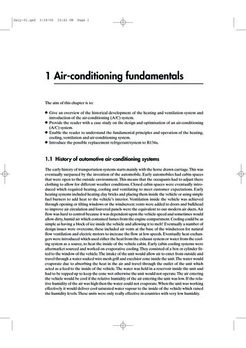
4-2. External dimensions(1) When using L-fittingsUnit: mm (in)L-fitting(supplied)253 (10)240 (9-8/16)209 (8-4/16)L-fitting(supplied)38(1-8/16)100 (3-15/16)169 (6-11/16)92 (3-10/16)172 (6-13/16)(2) When using DIN rail23 (15/16)150 (5-15/16)DIN railDIN rail attachment(supplied)DIN rail auxiliarybracket(supplied)46 (1-13/16)WT07936X0310
5. InstallationTest runs, inspection, and service must be performed by qualified personnel in accordancewith this manual. Incorrect use may result in injury, electric shock, malfunction, or fire.Do not install the controller where there is a risk of flammable gas leaks. If flammable gasaccumulates around the controller, it may ignite and cause a fire or explosion.Take appropriate safety measures against earthquakes to prevent the controller fromcausing injury.To prevent injury, install the controller on a flat surface strong enough to support itsweight.To reduce the risk of short circuits, current leakage, electric shock, malfunction, smoke, orfire, do not install the controller in a place exposed to water or in a condensingenvironment.WT07936X0311
5-1. Items not includedThe following items are required to install the EW-50.Items not includedSpecificationsLocknuts and bushingMust be suitable for the conduit tube to be used.Sleeved ring terminalM3.5 ring terminal (for AC power cables (L/L1, N/L2) and M-NET transmission cables (A, B,S))M4 ring terminal (for protective ground wire)AC power cable/Protectiveground wireType: Sheathed cable (should not be lighter than ordinary sheathed cable IEC 60227.)(designation 60227 IEC 53)*1Recommended type: VCT, VVF, VVR, or its equivalentSize: 0.75 to 2 mm² (ø1.0 to ø1.6 mm), AWG 18 to 14Protective ground wire color: green/yellow** Use a wire with an appropriate diameter so that the wire can be fixed with the cable tie below theterminal block. A diameter of 10 mm (25/64 in) is recommended.Transmission cableType: Shielded cable CPEVS ø1.2 to ø1.6 mm CVVS 1.25 to 2 mm²** CPEVS: PE*2 insulated PVC*2 jacketed shielded communication cable** CVVS: PVC*2 insulated PVC*2 jacketed shielded control cableRelay (for external input)Contact ratingRated voltage: 12 or 24 VDCRated current: 0.1 A or aboveMinimum applied load: DC 1 mARelay (for external output)Operation coilRated voltage: 12 or 24 VDCPower consumption: Max. 0.9 WElectrical wire for pulse inputType: Copper wire that is suitable for the terminal block of the EW-50Size Single wire: ø0.65 to ø1.2 mm, AWG 21 to 16 Twisted wire: 0.75 to 1.25 mm², AWG 18 to 16Must output dry voltage contact pulse for each unit pulse.Output pulse type: Semiconductor relayPulse width: 100 to 300 ms (Resting interval: Min. 100 ms)Min. 100 msWatt-hour meter100 to 300 msOutput pulse unit: 0.1/1.0/10/100 kWh/pulse** An output pulse unit of 1 kWh/pulse or below is recommended.LAN cableCategory 5 or above straight cable (Max. 100 m (328 ft))Switching HUBA communication speed of 100 Mbps or faster is recommended.FuseOvercurrentbreaker (fuse orcircuit breaker) Circuit breakerRated current: 3 A** When using a fuse, use it in combination with a switch (rated current: 3 A).Type: Bipolar (2P2E)Rated current: 3 AEarth leakage breakerType: Bipolar (2P2E)Rated current: 3 ARated current sensitivity: 30 mAOperation time: Max. 0.1 secPCRefer to the Instruction Book (Integrated Centralized Control Web) for PC requirements.*1 For the U.S. and Canada: designation NEC (NEPA70) or CEC*2 PE: Polyethylene, PVC: Polyvinyl chloride5-2. Items sold separatelyItems sold separatelyExternal input/output adapterWT07936X03Model nameRemarksPAC-YG10HA-ERequired when using the external input/output function12
5-3. Installation spaceThe EW-50 must be installed inside the metal control box.Either the supplied L-fittings or DIN rail attachments can be used for the installation.Leave a space around the EW-50 as shown in the figure below.Unit: mm (in)50 (2)50 (2)50 (2)50 (2)50 (2)50 (2)50 (2)50 (2)DIN rail150 (6)150 (6)DIN rail100 (4)100 (4)When using L-fittingsWT07936X03When using DIN rail13
5-4. Installation proceduresNote Connect the necessary cables and wires before installing EW-50, referring to chapters 6 and 9. Do not install the unit where the unit may continuously receive vibration. The continuous vibration may cause the connectorsto disconnect.5-4-1. Method 1: Installation using L-fittings1. Have a metal control box ready.2. Cut screw holes on the surface on which the EW-50 will be installed as shown in the figure below, taking into considerationthe installation space.3. Attach the supplied two L-fittings to the EW-50 with the supplied roundhead screws (M3 6).4. Properly install the EW-50 with the M4 screws (not supplied) inside the metal control box as shown in the figure below.① Temporarily tighten the top M4 screws.② Temporarily place the M4 screws through the screw holes at the top of the L-fitting.③ Tighten the bottom M4 screws.④ Tighten the top M4 screws.100 (4)Unit: mm (in)M4 screw(not supplied)②Roundhead screw(M3 -50M4Inside the metal controlbox③Note The EW-50 to which the L-fittings are attached must be fixed to the metal control box with total of four M4 screws to preventit from falling. The surface on which the EW-50 will be installed needs to be strong enough to support its weight (1.7 kg (4 lbs) each).WT07936X0314
5-4-2. Method 2: Installation using DIN rail1. Have a metal control box ready.2. Attach the supplied two DIN rail attachments to the EW-50 with the supplied roundhead screws (M3 12).3. Attach the supplied DIN rail auxiliary bracket to the EW-50 with the supplied roundhead screws (M3 6).EW-50DIN rail attachment(supplied)Roundhead screw (M3 12)(supplied)DIN rail auxiliary bracket(supplied)Roundhead screw (M3 6)(supplied)4. Mount the DIN rail (not supplied) to the metal control box.** Use a DIN rail of 35 mm (1-7/16 in) width.Unit: mm (in)Max. 200 (7-14/16)Note To secure the strength, the screw pitch must be 200 mm (7-7/8 in) or less when DIN rail is mounted to the metal control box. The surface on which the EW-50 will be installed needs to be strong enough to support its weight (1.7 kg (4 lbs) each). Do not install the EW-50 where it may receive vibration. To avoid the contact of the DIN rail fixing screws with the DIN rail attachment, do not tighten the fixing screws at the shadedareas in the figure below.Do not tighten the fixing screw here.WT07936X0315
[Mounting/removing the EW-50 on/from the DIN rail]MountingRemoving(1) Mounting1. Hook the upper side of the attachments to the DIN rail.2. Push the lower part of the EW-50 until it snaps into place.Note Ensure that the DIN rail attachments are fixed securely in place to the DIN rail.(2) Removing1. Pull the lower part of the EW-50 toward you.2. Remove the EW-50 from the DIN rail.WT07936X0316
6. Wiring connectionsTo reduce the risk of malfunction, smoke, fire, or damage to the controller, do not connectthe power cable to the signal terminal block.To reduce the risk of injury or electric shock, switch off the main power before performingelectrical work.Electrical work must be performed by qualified personnel in accordance with localregulations and the instructions provided in this manual. Only use specified cables anddedicated circuits. Inadequate power source capacity or improper electrical work willresult in electric shock, malfunction, or fire.To reduce the risk of electric shock, install an overcurrent breaker and an earth leakagebreaker on the power supply. To reduce the risk of electric shock, smoke, or fire, install anovercurrent breaker for each controller.Proper grounding must be provided by qualified personnel. Do not connect the protectiveground wire to a gas pipe, water pipe, lightning rod, or telephone wire. Improper groundingmay result in electric shock, smoke, fire, or malfunction due to electrical noiseinterference.To avoid malfunction, do not bundle power cables and signal cables together or placethem in the same metallic conduit.6-1. Removing/reinstalling the service cover(1) Removing1. Unscrew the two fixing screws on the service cover.2. Remove the service cover.Service coverOpenings on the EW-50Fixing screwsHooks on the service coverWT07936X0317
(2) Reinstalling1. Insert the AC power cables and M-NET transmission cables into the openings, and then insert the hooks to the openings.Note: Do not pinch the cables between the EW-50 body and the service cover.2. Screw down the service panel with the two fixing screws.3. Check that there are no pinched cables between the EW-50 body and the service cover.Opening for M-NET transmission cablesOpening for AC power cablesDo not pinch the cables between theEW-50 body and the service cover.WT07936X0318
6-2. Connecting AC power cables and M-NET transmission cablesEW-50Outdoor unitTB7Overcurrent breakerM-NET transmission cablesfor centralized controlEarth leakage breaker100–240 VACAC power cables6-2-1. AC power cables and protective ground wire1. Attach M3.5 sleeved ring terminals to the AC power cables, and attach an M4.0 sleeved ring terminal to the protective groundwire.2. Connect the AC power cables to the power supply terminal block, and connect the protective ground wire to the groundterminal.Note: Thread the protective ground wire through the guides to prevent the wire from moving when it is retightened to the ground terminal.3. Fix the cables in place with the supplied cable tie.Protectiveground wire45 mm(1-13/16 in)or lessAC power cableSheath100–240 VACCable tie (supplied)GuideGuideNote Make the protective ground wire 25 mm (1 in) longer than the AC power cables (L/L1, N/L2). Tighten the terminal screws to a torque of 1.0 to 1.3 N m. Properly fix the cable sheaths in place with the supplied cable ties. The distance between the sheath end and the ringterminal must be 45 mm (1-13/16 in) or less.Cable tie (supplied)Cable sheathWT07936X0319
6-2-2. M-NET transmission cables (Centralized control transmission cables)1.2.3.4.Attach M3.5 sleeved ring terminals to the M-NET transmission cables (A, B, Shield).Connect the M-NET transmission cables to the M-NET terminal block.Fix the cables in place with the supplied cable tie.When the power is supplied from the unit other than the EW-50, disconnect the M-NET power jumper from CN21. (Refer tosection 2-1 “Part names” for the location of CN21.)CN2145 mm (1-13/16 in)or lessM-NET transmission cables A and BM-NET transmission cable S (Shield)SheathCable tie (supplied)To outdoor unitNote Provide a single point ground for the shield of the centralized control transmission cable. (Provide the appropriate groundingaccording to local standards.) When leaving the M-NET power jumper connected to CN21 on the AE-200/AE-50/EW-50, the M-NET S (shield) terminal ofTB3 is connected to the ground terminal block on the unit, and the ground is supplied via the protective ground wire. When disconnecting the M-NET power jumper from CN21 on the AE-200/AE-50/EW-50, provide a ground point at a powersupply unit (PAC-SC51KUA). Tighten the terminal screws to a torque of 1.0 to 1.3 N m. Properly fix the cable sheaths in place with the supplied cable ties. The distance between the sheath end and the ringterminal must be 45 mm (1-13/16 in) or less.Cable tie (supplied)Cable sheathWT07936X0320
6-3. Connecting the LAN cableTo prevent unauthorized access, always use a security device such as a VPN router whenconnecting to the Internet.Connect the LAN cable to the LAN1 port on the EW-50. (The LAN2 port is exclusively used for BACnet function.) The LAN cable is not supplied. Use a category 5 or above straight LAN cable. Use a switching HUB compatible with 100 BASE. The maximum distance between the switching HUB and AE-200/AE-50/EW-50 is 100 m (328 ft). The recommended number of connected devices such as gateway, router, layer 3 switch, or HUB between theAE-200/AE-50/EW-50 is four or less. (Transmission round-trip delay time must not exceed one second. If the transmissiondelay time is long, a communication error may be detected. Check the transmission delay time, referring to section 6-4.)LAN1LAN2 (exclusive use for BACnet )Note LAN must be installed before the unit installation. Route the LAN cable to the EW-50 in the same way as the M-NETtransmission cables. When connecting the EW-50 to an existing LAN, consult the system administrator to decide the IP address.6-4. Confirming the LAN transmission delay timeConnect a monitoring PC to a device such as HUB that is connected to the AE-200/AE-50/EW-50. Send acommand from the PC to the AE-50/EW-50, and receive the response from the AE-50/EW-50. Check the timebetween sending and receiving on the PC display.(1) Sample system connectionAE-200EW-50Switching HUBMax.100 m (328 ft)Max.100 m (328 ft)Monitoring PCMax. 100 m (328 ft)WT07936X0321
(2) Checking the transmission delay time① Click [Start] [Program] [Accessories] [Command Prompt] on the monitoring PC.** The procedure may vary depending on the OS.② Enter [ping (IP address of AE-200/AE-50/EW-50)], and press the Enter button.([ping -w 1000 192.168.1.1] is entered on the sample screen below.)③ Check that the transmission delay time that appears on the screen is 1000 ms or below.(The transmission delay time is “Ma
EW-50A/EW-50E is a total management system. Any connected air conditioning systems can be operated or monitored on the Web browser. EW-50A/EW-50E can also be used as an expansion controller of AE-200A/AE-200E. By connecting AE-200A/AE-200E, up to 200 indoor units and other equipment can be controlled.