Transcription
Daly-01.qxd3/18/0610:42 PMPage 11 Air-conditioning fundamentalsThe aim of this chapter is to: Give an overview of the historical development of the heating and ventilation system andintroduction of the air-conditioning (A/C) system.Provide the reader with a case study on the design and optimisation of an air-conditioning(A/C) system.Enable the reader to understand the fundamental principles and operation of the heating,cooling, ventilation and air-conditioning system.Introduce the possible replacement refrigerant/system to R134a.1.1 History of automotive air-conditioning systemsThe early history of transportation systems starts mainly with the horse drawn carriage.This waseventually surpassed by the invention of the automobile. Early automobiles had cabin spacesthat were open to the outside environment. This means that the occupants had to adjust thereclothing to allow for different weather conditions. Closed cabin spaces were eventually introduced which required heating, cooling and ventilating to meet customer expectations. Earlyheating systems included heating clay bricks and placing them inside the vehicle or using simplefuel burners to add heat to the vehicle’s interior. Ventilation inside the vehicle was achievedthrough opening or tilting windows or the windscreen; vents were added to doors and bulkheadto improve air circulation and louvered panels were the equivalent to our modern air ducts. Airflow was hard to control because it was dependent upon the vehicle speed and sometimes wouldallow dirty, humid air which contained fumes from the engine compartment. Cooling could be assimple as having a block of ice inside the vehicle and allowing it to melt! Eventually a number ofdesign issues were overcome, these included air vents at the base of the windscreen for naturalflow ventilation and electric motors to increase the flow at low speeds. Eventually heat exchangers were introduced which used either the heat from the exhaust system or water from the cooling system as a source, to heat the inside of the vehicle cabin. Early cabin cooling systems wereaftermarket sourced and worked on evaporative cooling. They consisted of a box or cylinder fitted to the window of the vehicle.The intake of the unit would allow air to enter from outside andtravel through a water soaked wire mesh grill and excelsior cone inside the unit.The water wouldevaporate due to absorbing the heat in the air and travel through the outlet of the unit whichacted as a feed to the inside of the vehicle. The water was held in a reservoir inside the unit andhad to be topped up to keep the cone wet otherwise the unit would not operate. The air enteringthe vehicle would be cool if the relative humidity of the air entering the unit was low. If the relative humidity of the air was high then the water could not evaporate.When the unit was workingeffectively it would deliver cool saturated water vapour to the inside of the vehicle which raisedthe humidity levels. These units were only really effective in countries with very low humidity.
Daly-01.qxd3/18/06210:42 PMPage 2Automotive Air-conditioning and Climate Control SystemsIn 1939 Packard marketed the first mechanical automotive A/C system which worked on aclosed cycle. The system used a compressor, condenser, receiver drier and evaporator (fittedinside the boot/trunk) to operate the system. The only system control was a blower switch.Packard marketing campaign included:‘Forget the heat this summer in the only air-conditionedcar in the world.’ The major problem with the system was that the compressor operated continuously (had no clutch) and had to have the belt removed to disengage the system which was generally during the winter months. Over the period 1940–41 a number of manufacturers made vehicleswith A/C systems but these were in small volume and not designed for the masses. It wasn’t untilafter World War II that Cadillac advertised a new feature for the A/C system that located the A/Ccontrols on the rear parcel shelf, which meant that the driver had to climb into the back seat toswitch the system off. This was still better than reaching under the bonnet/hood to remove thedrive belt. In 1954–55 Nash-Kelvinator introduced air-conditioning for the mass market. It wasan A/C unit that was compact and affordable with controls on the dash and an electric clutch.The design and optimisation of an air-conditioning systemCase study – the air handling systemExperimental approachIn the past, the only way to evaluate a proposed air handling system design was to build aprototype and test it in the laboratory.The air handling components were placed on a test stand,conditioned air was supplied at the inlet and the airflow and temperature distribution at critical locations were measured. This approach takes a considerable amount of time and requiresthe construction of expensive prototypes. In addition, it provides little or no understanding ofwhy a design performed the way it did. In particular, testing is unable to detect details of recirculating areas, turbulence, temperature stratification and constrictions that adversely impactperformance and pressure loss. In addition, the performance of the system usually needs to beevaluated in many different configurations. For example, it sometimes is necessary to evaluatethe air handling system in different modes of operation – vent, floor, defrost and mixed – ateach of eight different temperature controls.Modern methods of designThe design process of modern vehicle systems improved with the introduction of ComputerAided Design (CAD), Computer Aided Engineering (CAE) and Computer Aided Manufacturing (CAM). CAD allows designs to be generated and visually appreciated on a computer.Standard components can be shared among manufacturers and suppliers to ensure that components assemble correctly. Designs can be sent to clients for verification and feedback. Designscan be modified and rechecked within short periods of time in a number of different formats,e.g. an STL file (stereolithography). Complex parts and assemblies can often be manufacturedvery quickly using rapid prototyping facilities (CAM). CAD also includes the facility to providevirtual testing. This is generally provided using additional modules or add-ins converting CADto CAE.A number of secondary schools in the UK have the use of Solidworks as a CAD package for their technology departments which include add-in modules like Cosmos Works forFinite Element Analysis and Computational Fluid Dynamics. Finite Element Analysis (FEA)is basically mechanical stress analysis and Computational Fluid Dynamics (CFD) analyses theflow of a fluid like air through or over complex geometry.These additional features are all computer based and use mathematical equations built into the software to predict variables likethe stress distribution of a component or assembly (FEA) or the flow of air through an air vent(CFD). All these tests would have originally been carried out manually with continual adjustments being made to a model to optimise it.
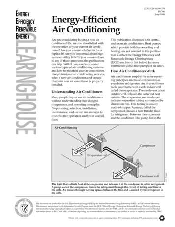
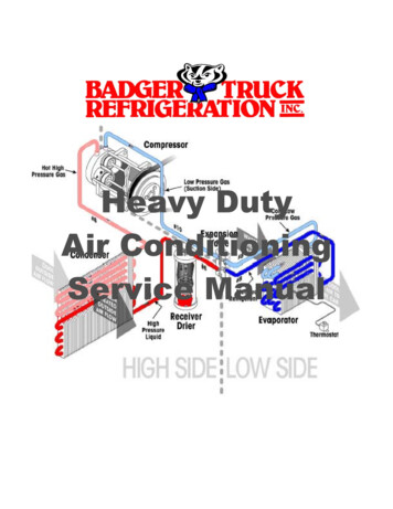
Daly-01.qxd3/18/0610:42 PMPage 3Air-conditioning fundamentals3Figure 1.1 Computer generated model designed using CAD (without ducting and vents)( 2005 Visteon All Rights Reserved)Figure 1.2 Air pressure loss predicted by CFD( 2005 Visteon All Rights Reserved)The processThe A/C system begins life as an idea driven by consumer needs or sometimes governmentlegislation. This leads to a specification. The specification will include minimum performancerequirements, temperatures, control zones, flow rates etc. This will lead to a number of conceptdesigns. The designs will have a number of computer generated models which will be presentedas possible solutions to the original specification.These need to be tested for their performance.Performance testing using CFD may include fluid velocity (air flow), pressure values and temperature distribution. Using CFD enables the analysis of fluid through very complex geometry and boundary conditions. The geometry typically includes ducts that expand and contract,change from round to square cross-sections, go through complex curves throughout their length,and have many branches and internal walls.As part of the analysis, a designer may change the geometry of the system or the boundaryconditions such as the inlet velocity, flow rate etc. and view the effect on fluid flow patterns.CFD is an efficient tool for generating parametric studies with the potential of significantlyreducing the amount of experimentation required to optimise the performance of a design.A fan performance curve can be inputted into a model. Without this feature, the user has toguess the flow within the enclosure, calculate the pressure using CFD and see if it matches the
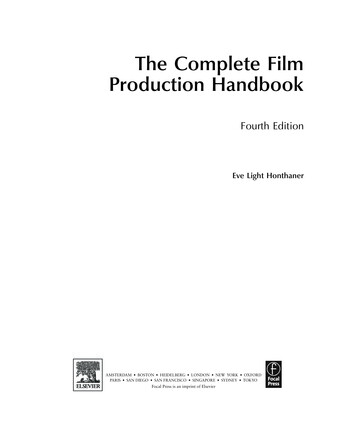
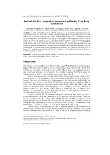
Daly-01.qxd3/18/06410:42 PMPage 4Automotive Air-conditioning and Climate Control SystemsFigure 1.3 Streamlines showing flow field in an air handling system( 2005 Visteon All Rights Reserved)Figure 1.4 Fan flow optimisation( 2005 Visteon All Rights Reserved)fan’s characteristics. If the pressure doesn’t match, then another guess has to be made. Normally,at least three iterations (test runs) are required to make a match.The software enters the fan curve directly into the model. Each analysis run then interactswith the fan curve to determine the precise operating conditions of the fan as part of the regular
Daly-01.qxd3/18/0610:42 PMPage 5Air-conditioning fundamentals5Figure 1.5 Improved fan design( 2005 Visteon All Rights Reserved)Figure 1.6 Human modelling for temperature distribution( 2005 Visteon All Rights Reserved)analysis. Using this technique, engineers can easily determine what type of fan is required to meetair flow requirements within the vehicle, normally 158 cubic feet per minute (75 litres/second)for heating and 300 cubic feet per minute (141.6 litres/second) for cooling.As a typical example of improvements consider the typical design specification of theHVAC system with respect to the temperature dial on the instrument panel. In other words,moving the dial from position one to position two should have the same impact on temperature as moving from position two to position three. In the past, the linearity of the temperaturedial could not be estimated until full vehicle prototypes were constructed. At that point, changeswere costly and the testing data provided little or no input on what type of changes were required.
Daly-01.qxd3/18/06610:43 PMPage 6Automotive Air-conditioning and Climate Control SystemsFigure 1.7 Prototype HVAC unit for testing( 2005 Visteon All Rights Reserved)Now, engineers can determine the linearity of a proposed design as soon as the solid model hasbeen created in a matter of days.They typically set up a series of analysis runs that evaluate eightdifferent temperature settings at each of the three HVAC system modes. In less than a week, theycan determine outlet air temperature at each setting.Once all CFD modelling is complete the prototypes are made to ensure the physical modelsoperate as predicted by the computer models. The accuracy of simulated and actual system performance can vary up to 10–15%. Generally, lead times are reduced and designs can be evaluatedmuch quicker allowing more time to optimise their working performance.1.2 Introduction to heating and ventilationHeating and ventilation in automotive transport is not just a function of temperature control.The safety of occupants to reduce driver fatigue, ensure good visibility and maintain comfort iskey to the successful design of such systems. A continual flow of air through the vehicles interiorreduces carbon dioxide levels, acts as a demister and prevents the build-up of odours. Carbondioxide in high concentration can cause a driver to be less responsive. There are recommendedventilation rates which specify the number of times the internal cubic capacity (air space) of thevehicle must be replaced per hour. Included in this calculation are the number of possible occupants and the internal volume of the vehicle. In some countries the performance of a heating andventilation system is governed by legislation. The heating and ventilation system combined withan air-conditioning system provide a temperature range for occupants to select from.This can bea real challenge due to some extreme weather conditions experienced across the globe. Oftenauxiliary booster devices are required to provide additional ‘heating’ or ‘cooling’ of the interior.The car heating systemHeat is a form of energy which means it cannot be destroyed. The principle of the heating andventilation system is to transfer enough heat from one point to another. The heater is a devicewhich heats the air entering or already inside the vehicle (recycled air). The heated air is thendirected to a combination of different places via a distribution of air ducts within the vehicle.
Daly-01.qxd3/18/0610:43 PMPage 7Air-conditioning fundamentals7Figure 1.8 Water cooling system(with the agreement of Toyota (GB) PLC)Figure 1.9 Heat exchangerThere are a number of different methods available to heat the air – exhaust heater, heat as aby-product of combustion, electric heater etc. Generally motor vehicles use heat from combustionwhich is transferred through water or air depending on whether the engine is water or air cooled.If the vehicle is air cooled then a system of shrouds is used to direct the heat from the externalsurface of the engine or exhaust or in some cases from the lubrication system towards the insideof the vehicle.Water-cooled enginesThe engine has a water cooling system which is used to maintain engine temperature by transferring combustion heat (as a by-product of the combustion process) away from the combustionchamber. The heated coolant is then carried from the combustion chamber through pipes to aheat exchanger.The heater exchanger (heater matrix)The heat exchanger, often called the matrix, is situated inside the vehicle housed within theheater assembly. It is designed to have a large surface area enabling air to pass over the surface
Daly-01.qxd3/18/06810:43 PMPage 8Automotive Air-conditioning and Climate Control Systemsof its fins. Fresh or recycled air (air from inside the vehicle) is directed under force over the surface of the heater core and then distributed via air and panel vents into the vehicle’s interior.The heater core is made up of tubes and fins which are made from aluminium alloy and havealuminium or plastic tanks attached to the core with inlet and outlet ports.Heat controlHeat control is determined by the occupants of the vehicle.This is done by selecting the requiredinterior temperature which the occupants require via a control panel. The control panel willeither control components to allow more or less water to enter the heat exchanger or allowmore or less air to flow over its external surface.These two systems used to control the heater’sthermal output are referred to as:1. Water flow type.2. Air mix type.Water flow typeThis system controls the amount of coolant flowing from the engine cooling system to the heatexchanger using a control valve. The control valve (Figure 1.11) varies the flow of coolantgoing inside the heat exchanger which in turn varies the temperature of the heater core.Regulation in such a system can be difficult especially with the coolant flow and temperaturebeing dependent upon engine speed and load. The system does not respond immediately toHeater coreWater valveFigure 1.10 Heat controlled by a water valve(with the agreement of Toyota (GB) PLC)1. Control solenoid2. Flow from engine3. Flow back to engine4. Flow from the heater core5. Flow to the heater core15243Figure 1.11 A solenoid operated water control valve(reproduced with the kind permission of Ford Motor Company Limited)
Daly-01.qxd3/18/0610:43 PMPage 9Air-conditioning fundamentals9change, for example if a lower temperature is required to the interior then the control valvewill restrict the flow of coolant to the heater core. To achieve the reduced temperature theheater core must lose the heat required to cool to the new selected temperature, thus giving offheat. A benefit of regulating the heater core is that it allows the whole volume of air to flowthrough the heater core itself, improving heating performance.Air mix typeThis system controls the volume of air allowed to flow over the surface of the heat exchangerusing an air mix/blend control door.The internal door directs air over or bypassing the heater coredepending on its position. The position is determined by the occupants who select a temperaturerange from hot to cold. If a mid-range temperature is selected then the quantity of air will flowover the heater core and a quantity will bypass the heater core.This air will then mix later in a mixing chamber to reach the final required temperature before leaving the heater assembly. The airmix control doors are generally operated by Bowden cable, vacuum or electronic servo. The negative aspect of such a design is that the use of a mixing chamber means that the heater assemblytends to be larger for the air mix type than the coolant controlled type. When not in use heat canradiate from the heater core warming natural air flow which is transferred to the cabin spacealthough this can be overcome by using a shut-off solenoid to stop the flow of coolant whenmaximum cooling effect is required. Positive aspects include quick response to changes in temperature and more accurate control of temperature variations.Air distribution through the interior of the vehicleA ventilator is a device used to direct air through the inside of a vehicle.There are generally twotypes of ventilator used on a vehicle:1. Natural flow ventilator.2. Forced flow ventilator (blower).Natural flow ventilatorThis is created by air pressure outside of the vehicle caused by the forward motion of the vehicle.As the vehicle moves in a forward direction positive and negative pressure is created on the vehicle’s surface due to its aerodynamic shape. Areas where positive pressure is created are idealplaces for air vents which allow air to enter the vehicle, travel through the interior and then exitthe vehicle via a vent often positioned in a negative pressure region.The air intake is positionedAir mix control damperHeater coreFigure 1.12 Heat controlled by an air mix control damper(with the agreement of Toyota (GB) PLC)
Daly-01.qxd3/18/061010:43 PMPage 10Automotive Air-conditioning and Climate Control SystemsFigure 1.13 Positive and negative pressure across the surface of the vehicle(with the agreement of Toyota (GB) PLC)at the bottom of the windscreen where static pressure is high so air under pressure can flow intothe vehicle. There are a number of downsides to this position:1. The engine compartment must be adequately sealed so no dissatisfying smells find thereway into the interior of the vehicle.2. Air flow is proportionate to vehicle speed causing lack of flow at low speeds and possibleexcessive noise and draughts at high speed.This is generally reduced by only allowing a small pressure differential between the intake andexhaust of air and adequate fan assistance. Air exhausts through outlets, which are mostlylocated in a rear pillar hidden behind a trim panel or behind the rear bumper.Air inlet and outletsIn Figure 1.14a to separate dirt particles and water from the air taken into the passenger compartment, the fresh air is fed through a cowl panel grille and pollen filter housing (2). This oftenhouses air filtration systems like pollen filters (1). The pollen filter is able to clean the fresh airfrom smaller particles, such as dust and pollen which are able to get through the cowl panel grille.The air outlets are arrangements of rubber flaps, mostly hidden behind the rear bumper orbehind a trim panel on the rear pillar. Because the pressure in the passenger compartment iscreated by the blower motor and natural air flow, the air outlets open and air exchange can takeplace. If there is no air flow through the vehicle interior, the flaps close to prevent exhaust fumesfrom entering. If vehicle ventilation is unsatisfactory, check the flaps for freedom of movement.In case of exhaust fumes reaching the luggage compartment, check the closing function ofthe flaps and their tightness.Forced air flowIn forced air ventilation systems an electric fan is fitted inside the vehicle. Fans are generally usedwhen vehicle speeds are low or comfort demands are high (demisting, heating and cooling).
Daly-01.qxd3/18/0610:43 PMPage 11Air-conditioning fundamentals1112(a)(b)Figure 1.14 (a) Fresh air inlet; (b) Fresh air inlet Ford Fiesta(reproduced with the kind permission of Ford Motor Company Limited)The blower fan can force air over the heater core allowing the heat to be transferred to the airwhich is distributed around the vehicle. Intake and outlet vents to the interior are generallylocated in the same position as the natural flow ventilator. Figure 1.8 shows the position of thefan (blower) within the system.Fan designAll fans are driven by an electric motor. The motor can rotate at varying speeds depending onthe current supplied to it (Chapter 3). The fan allows the air flow to be adjusted according tothe requirements of the occupants. Fans are generally divided into axial and centrifugal flowtypes. In axial type fans the air is drawn in and forced out parallel to the rotating axis. In the centrifugal type the air is blown in on the rotating axis and forced out perpendicular to the rotatingaxis (the direction of centrifugal force). The shape of the vanes of the fans are often profiled tomaximise flow and volume and minimise size and noise.The blower is a dominant low-frequencysource of noise, while at higher frequencies, additional air flow noise sources exist. Theseinclude high shear regions within the ducting, separation of flow due to flow obstructions, and theexit flow from air vents. Flow optimisation can be achieved using CFD (Computational FluidDynamics), which allows an engineer to analyse flow patterns and pressure regions within thesystem and make adjustments on the size, shape and position of components in efforts to makethe system as aerodynamically efficient and quite as possible. Other efforts included noiseisolation through the use of padding or positioning sources outside of the interior.Air filtrationPollen filterThe filter is located in the heater assembly housing before the heat exchanger (Figure 1.15aand b). Fibres in the filter prevent large particulates from entering the system and trap thereally small ones, the filter is electrostatically charged. Due to this electrostatic charge, the filter attracts particles like a magnet attracts iron filings. Besides removing visible particles, thefilter also removes pollen, spores and different types of dust etc. from the cabin air.Carbon filter and germicidal lampAn active carbon combination filter and/or a germicidal lamp are generally fitted as an optionin place of the pollen filter.The active carbon combination filter has the same advantages as the
Daly-01.qxd3/18/0612(a)10:43 PMPage 12Automotive Air-conditioning and Climate Control Systems(b)Figure 1.15 (a) Rear air flap. (b) Rear air flap Ford Fiesta (rubber flap removed)(reproduced with the kind permission of Ford Motor Company LimitedFigure 1.16 Centrifugal type fan assemblyFigure 1.17 Axial type fan assembly
Daly-01.qxd3/18/0610:43 PMPage 13Air-conditioning fundamentals13Figure 1.18 Air filtration system with pollen, carbon filter and germicidal lamp(with the agreement of Toyota (GB) PLC)pollen filter plus an effective active carbon layer. The active carbon layer neutralises unpleasant odours and keeps the air free of ozone. It also reduces diesel exhaust fumes from entering theinterior of the vehicle. A germicidal lamp is used in air-conditioning systems to kill any bacteriawhich enters or forms within the air filtration system.This also stops odours in the system throughthe build-up of bacteria (see section 5.4).Photo catalytic filterPhoto catalytic filters destroy pollutant gases and micro-organisms entering the vehicle. In lessthan five minutes the entire cabin air can be purified.Benefits:1. Continuous protection against potentially harmful external/internal pollutants and fromdiscomforting odours.2. Alleviation for allergy sufferers – micro-organisms causing allergies are destroyed.3. Extended service life of filters – 2000 hours, equivalent to approximately five years’ averagevehicle use.4. Complete destruction of pollutants compared to today’s carbon filters.
Daly-01.qxd3/18/061410:43 PMPage 14Automotive Air-conditioning and Climate Control Systems(a)(b)Figure 1.19 (a) Air distribution showing panel, face and floor vents (b) Manual control panel(reproduced with permission of Peugeot)Photo catalytic oxidation converts toxic compounds like carbon monoxide and nitrous oxide intobenign constituents such as carbon dioxide and water without wearing out or losing its effectiveness. When light strikes titanium oxide, hydrogen peroxide (H2O2) and hydroxyl radicals(OH) are formed. These two substances possess powerful oxidising properties and throughmutual interaction are able to decompose odorous substances into odourless carbon dioxideand water. A powerful oxidative also removes bacteria and deactivates viruses.Air quality sensingAn Air Quality Sensor (AQS) can be located in the main air inlet duct of the HVAC system.When a threshold for carbon monoxide or nitrogen dioxide is reached, the AQS communicatesto the HVAC system to initiate the air recirculation mode. For more information see section 3.2.Directing air flow and controlling temperature range can be manually selected by the occupants or electronically controlled via a control module. The heating system is designed to offera temperature range. Research into a comfort zone for passengers exists but is subjective dueto different nationalities that are acclimatised by the weather on their continents. The basicheating and ventilation system control panel contains a temperature control knob and a number of air distribution options.Air distribution unitThe air distribution unit is generally located under the instrument panel of the vehicle. Inside theair distribution unit there is a system of ducts and mixing/directing doors. In addition the unithouses the blower motor, the heater core and for vehicles with an air-conditioning system, theevaporator.The filtered incoming air from the intake panel grille is induced by the blower motorand is forced under centrifugal force to the air distribution unit.The air coming from the bloweris directed to the different air ducts through the moving doors in the air distribution unit. Thetemperature is regulated by mixing warm and cold air. The air is then directed to different airoutlets/air nozzles and panel vents. There are basically two ways for the ventilation system totake in air: fresh air from the outside and recirculated air from the interior. Therefore the airdistribution unit has two air inlets which are alternately closed by a door. Operating in recirculation mode allows to keep away unpleasant outside smells from the inside and it also improvesthe cooling output of the air-conditioning system. When recirculation mode is switched on for alonger period of time, the humidity level inside the vehicle will increase because of the moisturecontent of the breath of the passengers. This can lead to fogging on the windows. Switching tofresh air mode with air-conditioning system reduces the humidity of the inside of the vehicle.
Daly-01.qxd3/18/0610:43 PMPage 15Air-conditioning fundamentals15Face ductsAirintakeRecirculation door(closed)Air distribution door(rotary door) and outletto panelventsEvaporatorFigure 1.20 Heater assembly71.2.3.4.5.6.7.8.9.10.11.12.81265123411Air filtrationAir recirculation doorBlower motor and centrifugal fanHeat exchangerTemperature blend doorAir distribution doorPanel vent (not adjustable)Face/head vent (adjustable)Panel vent – rear passengers’ foot wellDucting to passenger foot wellFlow of coolantControl panel109Figure 1.21 Air recirculationSimplified view of system componentsFigure 1.21 shows the air intake door (recirculation door) is closed so no external air will enterthe vehicle except through a port which feeds the blower motor from the interior. The bloweris operating so air inside the vehicle will be recirculating around the vehicle’s interior.The heatexchanger will still heat the air as required as long as there is a difference in temperature andthe occupants have selected so via the control panel, which will vary the position of the temperature blend door (2). While the air is recirculating there is a danger that water vapour willcondense on the inside the vehicle’s windscreen. This is affected by the following: external air temperature;interior temperature;number of occupants;relative humidity of the air inside the vehicle.
Daly-01.qxd3/18/061610:43 PMPage 16Automotive Air-conditioning and Climate Control SystemsFigure 1.22 Demisting positionFigure 1.23 Demisting and heating the occupantsIf this occurs then air recirculation must stop and external air must enter the vehicle throughthe air intake door. Recirculation of air is often selected when driving in polluted areas, e.g.heavy traffic.In the demisting position (Figure 1.22) the air from outside is moved under force from theblower motor to the temperature blend door which is fully closed. This forces the total volumeof air to flow through the heater core where it will be heated and then directed by the top distribution door towards the windscreen and side windows. Note that no air is directed towardsthe occupants. This allows the maximum volume of air to flow to the windscreen to aid thedemisting process. This is done through the evaporation of the condensed water droplets onthe screen (see section 1.3).In Figure 1.23 the air intake door is fully
1 Air-conditioning fundamentals The aim of this chapter is to: Give an overview of the historical development of the heating and ventilation system and introduction of the air-conditioning (A/C) system. Provide the reader with a case study on the design and optimisation of an air-conditioning (A/C) system. Enable the reader to und