Transcription
Wang, S.K. and Lavan, Z. “Air-Conditioning and Refrigeration”Mechanical Engineering HandbookEd. Frank KreithBoca Raton: CRC Press LLC, 1999c1999 by CRC Press LLC
Air-Conditioning andRefrigerationShan K. Wang9.1Zalman LavanProfessor Emeritus, IllinoisInstitute of TechnologyIntroduction .9-2Air-conditioning Air-Conditioning Systems AirConditioning Project Development and System DesignIndividual Consultant9.2Psychrometrics .9-11Moist Air Humidity and Enthalpy Moist Volume, Density,Specific Heat, and Dew Point Thermodynamic Wet BulbTemperature and Wet Bulb Temperature Psychometric Charts9.3Air-Conditioning Processes and Cycles .9-18Air-Conditioning Processes Space Conditioning, SensibleCooling, and Sensible Heating Processes Humidifying andCooling and Dehumidifying Processes Air-ConditioningCycles and Operating Modes9.4Refrigerants and Refrigeration Cycles .9-34Refrigeration and Refrigeration Systems Refrigerants,Cooling Mediums, and Absorbents Classification ofRefrigerants Required Properties of Refrigerants IdealSingle-Stage Vapor Compression Cycle Coefficient ofPerformance of Refrigeration Cycle Subcooling andSuperheating Refrigeration Cycle of Two-Stage CompoundSystems with a Flash Cooler Cascade System Characteristics9.5Outdoor Design Conditions and IndoorDesign Criteria .9-48Outdoor Design Conditions Indoor Design Criteria andThermal Comfort Indoor Temperature, Relative Humidity,and Air Velocity Indoor Air Quality and Outdoor VentilationAir Requirements9.6Load Calculations .9-54Space Loads Moisture Transfer in Building Envelope Cooling Load Calculation Methodology Conduction HeatGains Internal Heat Gains Conversion of Heat Gains intoCooling Load by TFM Heating Load9.7Air Handling Units and Packaged Units .9-65Terminals and Air Handling Units Packaged Units Coils Air Filters Humidifiers9.8Refrigeration Components andEvaporative Coolers .9-76Refrigeration Compressors Refrigeration Condensers Evaporators and Refrigerant Flow Control Devices Evaporative Coolers 1999 by CRC Press LLC9-1
9-2Section 99.9Water Systems.9-87Types of Water Systems Basics Water Piping PlantBuilding Loop Plant-Distribution-Building Loop9.10 Heating Systems.9-95Types of Heating Systems9.11 Refrigeration Systems .9-103Classifications of Refrigeration Systems9.12 Thermal Storage Systems .9-114Thermal Storage Systems and Off-Peak Air-ConditioningSystems Ice-Storage Systems Chilled-Water StorageSystems9.13 Air System Basics.9-120Fan-Duct Systems System Effect Modulation of Air Systems Fan Combinations in Air-Handling Units and Packaged Units Fan Energy Use Year-Round Operation and Economizers Outdoor Ventilation Air Supply9.14 Absorption Systems .9-130Double-Effect Direct-Fired Absorption Chillers AbsorptionCycles, Parallel-, Series-, and Reverse-Parallel Flow9.15 Air-Conditioning Systems and Selection.9-135Basics in Classification Individual Systems PackagedSystems Central Systems Air-Conditioning SystemSelection Comparison of Various Systems Subsystems Energy Conservation Recommendations9.16 Desiccant Dehumidification andAir-Conditioning .9-152Introduction Sorbents and Desiccants Dehumidification Liquid Spray Tower Solid Packed Tower Rotary DesiccantDehumidifiers Hybrid Cycles Solid Desiccant AirConditioning Conclusions9.1 IntroductionAir-ConditioningAir-conditioning is a process that simultaneously conditions air; distributes it combined with the outdoorair to the conditioned space; and at the same time controls and maintains the required space’s temperature,humidity, air movement, air cleanliness, sound level, and pressure differential within predeterminedlimits for the health and comfort of the occupants, for product processing, or both.The acronym HVAC&R stands for heating, ventilating, air-conditioning, and refrigerating. The combination of these processes is equivalent to the functions performed by air-conditioning.Because I-P units are widely used in the HVAC&R industry in the U.S., I-P units are used in thischapter. A table for converting I-P units to SI units is available in Appendix X of this handbook.Air-Conditioning SystemsAn air-conditioning or HVAC&R system consists of components and equipment arranged in sequentialorder to heat or cool, humidify or dehumidify, clean and purify, attenuate objectionable equipment noise,transport the conditioned outdoor air and recirculate air to the conditioned space, and control and maintainan indoor or enclosed environment at optimum energy use.The types of buildings which the air-conditioning system serves can be classified as: Institutional buildings, such as hospitals and nursing homes Commercial buildings, such as offices, stores, and shopping centers 1999 by CRC Press LLC
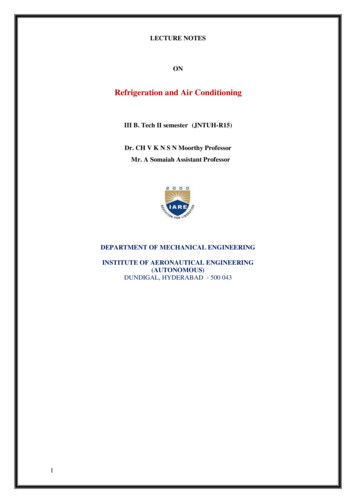
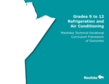
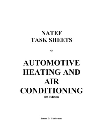
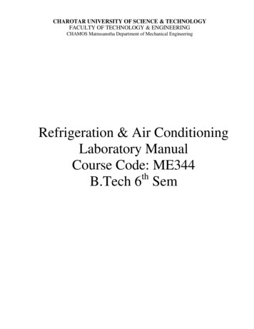
Air-Conditioning and Refrigeration9-3 Residential buildings, including single-family and multifamily low-rise buildings of three or fewerstories above grade Manufacturing buildings, which manufacture and store productsTypes of Air-Conditioning SystemsIn institutional, commercial, and residential buildings, air-conditioning systems are mainly for theoccupants’ health and comfort. They are often called comfort air-conditioning systems. In manufacturingbuildings, air-conditioning systems are provided for product processing, or for the health and comfortof workers as well as processing, and are called processing air-conditioning systems.Based on their size, construction, and operating characteristics, air-conditioning systems can beclassified as the following.Individual Room or Individual Systems. An individual air-conditioning system normally employseither a single, self-contained, packaged room air conditioner (installed in a window or through a wall)or separate indoor and outdoor units to serve an individual room, as shown in Figure 9.1.1. “Selfcontained, packaged” means factory assembled in one package and ready for use.Room airconditionerSupplyoutletReturngrilleFIGURE 9.1.1 An individual room air-conditioning system.Space-Conditioning Systems or Space Systems. These systems have their air-conditioning—cooling,heating, and filtration—performed predominantly in or above the conditioned space, as shown in Figure9.1.2. Outdoor air is supplied by a separate outdoor ventilation system.Unitary Packaged Systems or Packaged Systems. These systems are installed with either a single selfcontained, factory-assembled packaged unit (PU) or two split units: an indoor air handler, normally withductwork, and an outdoor condensing unit with refrigeration compressor(s) and condenser, as shown inFigure 9.1.3. In a packaged system, air is cooled mainly by direct expansion of refrigerant in coils calledDX coils and heated by gas furnace, electric heating, or a heat pump effect, which is the reverse of arefrigeration cycle.Central Hydronic or Central Systems. A central system uses chilled water or hot water from a centralplant to cool and heat the air at the coils in an air handling unit (AHU) as shown in Figure 9.1.4. Forenergy transport, the heat capacity of water is about 3400 times greater than that of air. Central systemsare built-up systems assembled and installed on the site.Packaged systems are comprised of only air system, refrigeration, heating, and control systems. Bothcentral and space-conditioning systems consist of the following.Air Systems. An air system is also called an air handling system or the air side of an air-conditioningor HVAC&R system. Its function is to condition the air, distribute it, and control the indoor environmentaccording to requirements. The primary equipment in an air system is an AHU or air handler; both ofthese include fan, coils, filters, dampers, humidifiers (optional), supply and return ductwork, supplyoutlets and return inlets, and controls. 1999 by CRC Press LLC
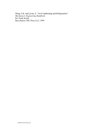
9-4Section 914Make-up airAHU (outdoorventilation terminalChilledwatersystemCondenserwater Chilledwater pumpFIGURE 9.1.2 A space-conditioning air-conditioning system (fan-coil system).Water Systems. These systems include chilled water, hot water, and condenser water systems. A watersystem consists of pumps, piping work, and accessories. The water system is sometimes called the waterside of a central or space-conditioning system.Central Plant Refrigeration and Heating Systems. The refrigeration system in the central plant of acentral system is usually in the form of a chiller package with an outdoor condensing unit. Therefrigeration system is also called the refrigeration side of a central system. A boiler and accessoriesmake up the heating system in a central plant for a central system, and a direct-fired gas furnace is oftenthe heating system in the air handler of a rooftop packaged system.Control Systems. Control systems usually consist of sensors, a microprocessor-based direct digitalcontroller (DDC), a control device, control elements, personal computer (PC), and communicationnetwork.Based on Commercial Buildings Characteristics 1992, Energy Information Administration (EIA) ofthe Department of Energy of United States in 1992, for commercial buildings having a total floor area 1999 by CRC Press LLC
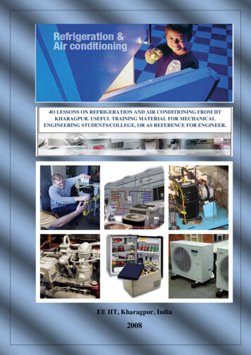
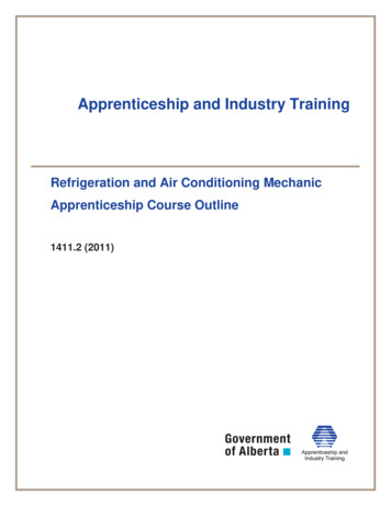
HeatingcoilAir-Conditioning and RefrigerationCondensingunitRecirculating airOutdoorairDX-coilSupplyfanSupplyductAir systemRooftoppackaged unitDX-coilCondensingunitCeiling ilter1ReturngrilleOutdoorairAir handler(air system)RefrigerationsystemWorship hallDDC controller(control system)FIGURE 9.1.3 A packaged air-conditioning system.9-5 1999 by CRC Press LLC
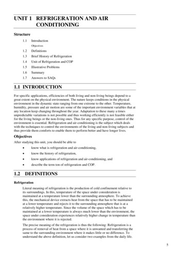
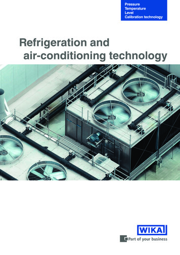
9-6Section AHU216Air erationmachine(a)FIGURE 9.1.4a A central air-conditioning system: schematic diagram.of 67,876 million ft2, of which 57,041 million ft2 or 84% is cooled and 61,996 million ft2 or 91% isheated, the air-conditioning systems for cooling include:Individual systemsPackaged systemsCentral systems19,239 million ft234,753 million ft214,048 million ft2(25%)(49%)(26%)Space-conditioning systems are included in central systems. Part of the cooled floor area has beencounted for both individual and packaged systems. The sum of the floor areas for these three systemstherefore exceeds the total cooled area of 57,041 million ft2. 1999 by CRC Press LLC
9-7Air-Conditioning and RefrigerationFan-poweredboxC ControllerT Temperature sensorM MotorF Velocity sensorS SwitchP Static pressure sensorElectricheating erConditioned spaceInterior zonePerimeter zoneControl E 9.1.4b A central air-conditioning system: air and control systems for a typical floor.Air-Conditioning Project Development and System DesignThe goal of an air-conditioning/HVAC&R system is to provide a healthy and comfortable indoorenvironment with acceptable indoor air quality, while being energy efficient and cost effective.ASHRAE Standard 62-1989 defines acceptable indoor air quality as “air in which there are no knowncontaminants at harmful concentrations as determined by cognizant authorities and with which a substantial majority (80% or more) of the people exposed do not express dissatisfaction.”The basic steps in the development and use of an air-conditioning project are design, installation,commissioning, operation, and maintenance. There are two types of air-conditioning projects: designbid and design-build. A design-bid project separates the design (engineering consultant) and installation(contractors) responsibilities. In a design-build project, the design is also done by the installationcontractor. A design-build project is usually a small project or a project having insufficient time to gothrough normal bidding procedures.In the building construction industry, air-conditioning or HVAC&R is one of the mechanical services;these also include plumbing, fire protection, and escalators.Air-conditioning design is a process of selecting the optimum system, subsystem, equipment, andcomponents from various alternatives and preparing the drawings and specifications. Haines (1994)summarized this process in four phases: gather information, develop alternatives, evaluate alternatives, 1999 by CRC Press LLC
9-8Section 9and sell the best solution. Design determines the basic operating characteristics of a system. After anair-conditioning system is designed and constructed, it is difficult and expensive to change its basiccharacteristics.The foundation of a successful project is teamwork and coordination between designer, contractor,and operator and between mechanical engineer, electrical engineer, facility operator, architect, andstructural engineer.Field experience is helpful to the designer. Before beginning the design process it is advisable to visitsimilar projects that have operated for more than 2 years and talk with the operator to investigate actualperformance.Mechanical Engineer’s ResponsibilitiesThe normal procedure in a design-bid construction project and the mechanical engineer’s iation of a project by owner or developerOrganizing a design teamDetermining the design criteria and indoor environmental parametersCalculation of cooling and heating loadsSelection of systems, subsystems, and their componentsPreparation of schematic layouts; sizing of piping and ductworkPreparation of contract documents: drawings and specificationsCompetitive biddings by various contractors; evaluation of bids; negotiations and modificationsAdvice on awarding of contractMonitoring, supervision, and inspection of installation; reviewing shop drawingsSupervision of commissioningModification of drawings to the as-built condition; preparation of the operation and maintenancemanual13. Handing over to the property management for operationDesign DocumentsDrawings and specifications are legal documents of a construction contract. The designer conveys theowner’s or developer’s requirements to the contractor through these documents. Drawings and specifications complement each other.Drawings should clearly and completely show, define, and present the work. Adequate plan andsectional views should be drawn. More often, isometric drawings are used to show the flow diagramsfor water or the supply, return, and exhaust air.Specifications include the legal contract between the owner and the contractor, installer, or vendorand the technical specifications, which describe in detail what kind of material and equipment shouldbe used and how they are to be installed.Most projects now use a format developed by the Construction Specifications Institute (CSI) calledthe Masterformat for Specifications. It includes 16 divisions. The 15000 Mechanical division is dividedinto the following: 1999 by CRC Press LLCSection 850Basic Mechanical Materials and MethodsMechanical InsulationFire ProtectionPlumbingHeating, Ventilating, and Air-ConditioningHeat GenerationRefrigerationHeat TransferAir Handling
9-9Air-Conditioning and RefrigerationSection No.158801595015990TitleAir DistributionControlsTesting, Adjusting, and BalancingEach section includes general considerations, equipment and material, and field installation. Designcriteria and selected indoor environmental parameters that indicate the performance of the HVAC&Rsystem must be clearly specified in the general consideration of Section 15500.There are two types of specifications: the performance specification, which depends mainly on therequired performance criteria, and the or-equal specification, which specifies the wanted vendor. Specifications should be written in simple, direct, and clear language without repetition.Computer-Aided Design and DraftingWith the wide acceptance of the PC and the availability of numerous types of engineering software, theuse of computer-aided drafting (CAD) and computer-aided design and drafting (CADD) has increasedgreatly in recent years. According to the 1994 CADD Application and User Survey of design firmsreported in Engineering Systems (1994[6]), “15% of the design firms now have a computer on everydesk” and “Firms with high productivity reported that they perform 95% on CADD.” Word processingsoftware is widely used to prepare specifications.Drafting software used to reproduce architectural drawings is the foundation of CADD. AutomatedCAD (AutoCAD) is the leading personal computer-based drafting tool software used in architecturaland engineering design firms.In “Software Review” by Amistadi (1993), duct design was the first HVAC&R application to beintegrated with CAD. Carrier Corp. DuctLINK and Softdesk HVAC 12.0 are the two most widely used duct designsoftware. Both of them convert the single-line duct layout drawn with CAD to two-dimensional(2D) double-line drawings with fittings, terminals, and diffusers. Tags and schedules of HVAC&R equipment, ductwork, and duct fittings can be produced as well. DuctLINK and Softdesk can also interface with architectural, electrical, and plumbing drawingsthrough AutoCAD software.Software for piping system design and analysis can also be integrated with CAD. The softwaredeveloped at the University of Kentucky, KYCAD/KYPIPE, is intended for the design and diagnosis oflarge water piping systems, has extensive hydraulic modeling capacities, and is the most widely used.Softdesk AdCADD Piping is relative new software; it is intended for drafting in 2D and 3D, linking toAutoCAD through design information databases.Currently, software for CADD for air-conditioning and HVAC&R falls into two categories: engineeringand product. The engineering category includes CAD (AutoCAD integrated with duct and piping system),load calculations and energy analysis, etc. The most widely used software for load calculations andenergy analysis is Department of Energy DOE-2.1D, Trane Company’s TRACE 600, and Carrier Corporation’s softwares for load calculation, E20-II Loads.Product categories include selection, configuration, performance, price, and maintenance schedule.Product manufacturers provide software including data and CAD drawings for their specific product.Codes and StandardsCodes are federal, state, or city laws that require the designer to perform the design without violatingpeople’s (including occupants and the public) safety and welfare. Federal and local codes must befollowed. The designer should be thoroughly familiar with relevant codes. HVAC&R design codes aredefinitive concerning structural and electrical safety, fire prevention and protection (particularly for gasor oil-fired systems), environmental concerns, indoor air quality, and energy conservation. 1999 by CRC Press LLC
9-10Section 9Conformance with ASHRAE Standards is voluntary. However, for design criteria or performance thathas not been covered in the codes, whether the ASHRAE Standard is followed or violated is the vitalcriterion, as was the case in a recent indoor air quality lawsuit against a designer and contractor.For the purpose of performing an effective, energy-efficient, safe, and cost-effective air-conditioningsystem design, the following ASHRAE Standards should be referred to from time to time: ASHRAE/IES Standard 90.1-1989, Energy Efficient Design of New Buildings Except New LowRise Residential Buildings ANSI/ASHRAE Standard 62-1989, Ventilation for Acceptable Indoor Air Quality ANSI/ASHRAE Standard 55-1992, Thermal Environmental Conditions for Human Occupancy ASHRAE Standard 15-1992, Safety Code for Mechanical Refrigeration 1999 by CRC Press LLC
9-11Air-Conditioning and Refrigeration9.2 PsychrometricsMoist AirAbove the surface of the earth is a layer of air called the atmosphere, or atmospheric air. The loweratmosphere, or homosphere, is composed of moist air, that is, a mixture of dry air and water vapor.Psychrometrics is the science of studying the thermodynamic properties of moist air. It is widely usedto illustrate and analyze the change in properties and the thermal characteristics of the air-conditioningprocess and cycles.The composition of dry air varies slightly at different geographic locations and from time to time.The approximate composition of dry air by volume is nitrogen, 79.08%; oxygen, 20.95%; argon, 0.93%;carbon dioxide, 0.03%; other gases (e.g., neon, sulfur dioxide), 0.01%.The amount of water vapor contained in the moist air within the temperature range 0 to 100 F changesfrom 0.05 to 3% by mass. The variation of water vapor has a critical influence on the characteristics ofmoist air.The equation of state for an ideal gas that describes the relationship between its thermodynamicproperties covered in Chapter 2 ispv RTR(9.2.1)pV mRTR(9.2.2)orwherepvRTRVm pressure of the gas, psf (1 psf 144 psi)specific volume of the gas, ft3/lbgas constant, ftlbf /lbm Rabsolute temperature of the gas, Rvolume of the gas, ft3mass of the gas, lbThe most exact calculation of the thermodynamic properties of moist air is based on the formulationsrecommended by Hyland and Wexler (1983) of the U.S. National Bureau of Standards. The psychrometriccharts and tables developed by ASHRAE are calculated and plotted from these formulations. Accordingto Nelson et al. (1986), at a temperature between 0 and 100 F, enthalpy and specific volume calculationsusing ideal gas Equations (9.2.1) and (9.2.2) show a maximum deviation of 0.5% from the results ofHyland and Wexler’s exact formulations. Therefore, ideal gas equations are used in the developmentand calculation of psychrometric formulations in this handbook.Although air contaminants may seriously affect human health, they have little effect on the thermodynamic properties of moist air. For thermal analysis, moist air may be treated as a binary mixture ofdry air and water vapor.Applying Dalton’s law to moist air:pat pa pwwhere(9.2.3)pat atmospheric pressure of the moist air, psiapa partial pressure of dry air, psiapw partial pressure of water vapor, psiaDalton’s law is summarized from the experimental results and is more accurate at low gas pressure.Dalton’s law can also be extended, as the Gibbs-Dalton law, to describe the relationship of internalenergy, enthalpy, and entropy of the gaseous constituents in a mixture. 1999 by CRC Press LLC
9-12Section 9Humidity and EnthalpyThe humidity ratio of moist air, w, in lb/lb is defined as the ratio of the mass of the water vapor, mw tothe mass of dry air, ma, or(pw mw ma 0.62198 pwat pw )(9.2.4)The relative humidity of moist air, ϕ, or RH, is defined as the ratio of the mole fraction of water vapor,xw , to the mole fraction of saturated moist air at the same temperature and pressure, xws. Using the idealgas equations, this relationship can be expressed as:ϕ x w x ws T , p pw pws T , p(9.2.5)andx w nw (na nw ) ;x ws nws (na nws )xa x w 1(9.2.6)wherepws pressure of saturated water vapor, psiaT temperature, Fna, nw , nws number of moles of dry air, water vapor, and saturated water vapor, molDegree of saturation µ is defined as the ratio of the humidity ratio of moist air, w, to the humidity ratioof saturated moist air, ws, at the same temperature and pressure:µ w ws T , p(9.2.7)The difference between ϕ and µ is small, usually less than 2%.At constant pressure, the difference in specific enthalpy of an ideal gas, in Btu/lb, is h cp T. Herecp represents the specific heat at constant pressure, in Btu/lb. For simplicity, the following assumptionsare made during the calculation of the enthalpy of moist air:1.2.3.4.At 0 F, the enthalpy of dry air is equal to zero.All water vapor is vaporized at 0 F.The enthalpy of saturated water vapor at 0 F is 1061 Btu/lb.The unit of the enthalpy of the moist air is Btu per pound of dry air and the associated watervapor, or Btu/lb.Then, within the temperature range 0 to 100 F, the enthalpy of the moist air can be calculated as:(h cpd T w hg 0 cpsT) 0.240T w(1061 0.444T )(9.2.8)where cpd, cps specific heat of dry air and water vapor at constant pressure, Btu/lb F. Their meanvalues can be taken as 0.240 and 0.444 Btu/lb F, respectively.hg0 specific enthalpy of saturated water vapor at 0 F. 1999 by CRC Press LLC
9-13Air-Conditioning and RefrigerationMoist Volume, Density, Specific Heat, and Dew PointThe specific moist volume v, in ft3/lb, is defined as the volume of the mixture of dry air and the associatedwater vapor when the mass of the dry air is exactly 1 lb:v V ma(9.2.9)where V total volume of the moist air, ft3. Since moist air, dry air, and water vapor occupy the samevolume,v Ra TR pat (1 1.6078w)(9.2.10)where Ra gas constant for dry air.Moist air density, often called air density ρ, in lb/ft3, is defined as the ratio of the mass of dry air tothe total volume of the mixture, or the reciprocal of the moist volume:ρ ma V 1 v(9.2.11)The sensible heat of moist air is the thermal energy associated with the change of air temperaturebetween two state points. In Equation (9.2.8), (cpd wcps)T indicates the sensible heat of moist air, whichdepends on its temperature T above the datum 0 F. Latent heat of moist air, often represented by whfg0,is the thermal energy associated with the change of state of water vapor. Both of them are in Btu/lb.Within the temperature range 0 to 100 F, if the average humidity ratio w is taken as 0.0075 lb/lb, thespecific heat of moist air cpa can be calculated as:cpa cpd wcps 0.240 0.0075 0.444 0.243 Btu lb F(9.2.12)The dew point temperature Tdew, in F, is the temperature of saturated moist air of the moist air samplehaving the same humidity ratio at the same atmospheric pressure. Two moist air samples of similar dewpoints Tdew at the same atmospheric pressure have the same humidity ratio w and the same partial pressureof water vapor pw.Thermodynamic Wet Bulb Temperature and Wet Bulb TemperatureThe thermodynamic wet bulb temperature of moist air, T *, is equal to the saturated state of a moist airsample at the end of a constant-pressure, ideal adiabatic saturation process:()h1 ws* w1 hw* hs*(9.2.13)where h1, hs* enthalpy of moist air at the initial state and enthalpy of saturated air at the end of theconstant-pressure, ideal adiabatic saturation process, Btu/lbw1, ws* humidity ratio of moist air at the initial state and humidity ratio of saturated air at theend of the constant-pressure, ideal adiabatic saturation process, lb/lbhw* enthalpy of water added to the adiabatic saturation process at temperature T *, Btu/lbAn ideal adiabatic saturation process is a hypothetical process in which moist air at initial temperatureT1, humidity ratio w1, enthalpy h1, and pressure p flows over a water surface of infinite length througha well-insulated channel. Liquid water is therefore evaporated into water vapor at the expense of thesensible heat of the moist air. The result is an increase of humidity ratio and a drop of temperature untilthe moist air is saturated at the thermodynamic wet bulb temperature T * during the end of the idealadiabatic saturation process. 1999 by CRC Press LLC
9-14Section 9The thermodynamic wet bulb temperature T * is a unique fictitious property of moist air that dependsonly on its initial properties, T1, w1, or h1.A sling-type psychrometer, as shown in Figure 9.2.1, is an instrument that determines the temperature,relative humidity, and thus the state of the moist air by measuring its dry bulb and wet bulb temperatures.It consists of two mercury-in-glass thermometers. The sensing bulb of one of them is dry and is calledthe dry bulb. Another sensing bulb is wrapped with a piece of cotton wick, one end of which dips intoa water tube. This wetted sensing bulb is called the wet bulb and the temperature measured by it iscalled the wet bulb temperature T′.SpindleHandleCottonwickDry bulbMoist airT1, w1, h1, pWet bulbWater tubeFIGURE 9.2.1 A sling psychrometer.When unsaturated moist air flows over the surface of the wetted cotton wick, liquid water evaporatesfrom its surface. As it absorbs sensible heat, mainly from the surrounding air, the wet bulb temperaturedrops. The difference between the dry and wet bulb temperatures is called wet bulb depression (T – T′).Turning the handle forces the surrounding air to flow over the dry and wet bulbs at an air velocitybetween 300 to 600 fpm. Distilled water must be used to wet the cotton wick.At steady state, if heat conduction along the thermometer stems is neglected and the temperature ofthe wetted cotton wick is equal to the wet bulb temperature of the moist air, as the sensible heat transferfrom the surrounding moist air to the cotton wick exactly equals the latent heat required for evaporation,the heat and mass transfer per unit area of the wet bulb surface can be evaluated as:hc (T T ′) hr (Tra T ) hd (ws′ w1 )where hc, hr mean conductive and radiative heat transfer coefficient, Btu/hr ft2 Fhd m
A space-conditioning air-conditioning system (fan-coil system). 2 Chilled water pump Centrifugal refrigeration system Condenser pumps Condenser water system Conditioned space Electric heater T2 2 1 Conditioned space T1 1 1 4 3 Outdoor air 3 DDC panel Make-up air AHU (outdoor ventilation air) T3 3 3 4 5 Fan-coil Fan-coil terminal Chilled water .