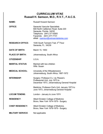
Transcription
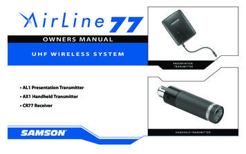
O W N E R S M A N UA LUHF WIRELESS SYSTEMPRESENTATIONTRANSMIT TER AL1 Presentation Transmitter AX1 Handheld Transmitter CR77 ReceiverHA N D HEL D TR A N SMI T TER
ENGLISHIntroductionQuickStartGuided Tour - CR77 ReceiverGuided Tour - UM1 ReceiverGuided Tour - AX1 Handheld TransmitterGuided Tour - AL1 Presentation TransmitterSetting Up and Using Your AirLine SystemSpecificationsAppendix A: Channel PlanAppendix B: Attaching The Lanyard to the AL1FRANCAISIntroductionPrise en mainVisite guidée – Récepteur CR77Visite guidée – Récepteur UM1Visite guidée – Emetteur main AX1Visite guidée – Emetteur de presentation AL1Configuration et utilisation des systèmes AirLineSpécificationsAppendix A: Tableau de conversion de fréquenceAppendix B: Attaching The Lanyard to the AL1Copyright 2013, v6Samson Technologies Corp.45 Gilpin AvenueHauppauge, New York 11788-8816Phone: 1-800-3-SAMSON (1-800-372-6766)Fax: 631-784-2201Table of r EinstiegÜbersicht - Empfänger CR77Übersicht - Empfänger UM1Übersicht - Hand-Sender AX1Übersicht - Presentation-Sender AL1Konfiguration und Betrieb der AirLine-SystemeTechnische DatenAnhang A: Frequenzzuordnung der EmpfangskanäleAnhang B: Attaching The Lanyard to the IntroducciónArranque rápidoRecorrido guiado – Receptor CR77Recorrido guiado – Receptor UM1Recorrido guiado – Transmisor manual AX1Recorrido guiado – Transmisor de presentation AL1Ajuste y uso de su sistema AirLineEspecificacionesApéndice A: Tabla de conversión de frecuenciasApéndice B: Attaching The Lanyard to the AL157586063666871757778
IntroductionSamson AirLineThere are two different Samson AirLine systems detailed in this manual. Both operate in the 801 - 805 MHz UHF frequency range and eachcontains a CR77 receiver or a UM1 micro diversity receiver (optimized for the production of professional audio tracks to accompany yourvideo shoot or live broadcast). The AirLine UHF Microphone System contains an AX1 hand-held transmitter, which plugs into any standardwired dynamic microphone. The AirLine UHF Presentation System contains an AL1 presentation transmitter, which contains a built-in electret condenser microphone and connection for an optional lavalier microphone.In this manual, you’ll find a more detailed description of the features of all AirLine systems, as well as a guided tour through all components,step-by-step instructions for setting up your system and full specifications. If your AirLine system was purchased in the United States, you’llalso find a warranty card enclosed—don’t forget to fill it out and mail it! This will enable you to receive online technical support and willallow us to send you updated information about this and other Samson products in the future. If your AirLine system was purchased outside of the U. S., contact your local distributor for warranty details. Also, be sure to check out our website (http://www.samsontech.com) forcomplete information about our full product line.SPECIAL NOTE for U.S. purchasers: Should your AirLine system ever require servicing, a Return Authorization number (RA) is necessary.Without this number, the unit will not be accepted. If your AirLine system was purchased in the United States, please call Samson at 1-800372-6766 for a Return Authorization number prior to shipping your system. If possible, return the unit in its original carton and packingmaterials. If your AirLine system was purchased outside of the U. S., contact your local distributor for information.3ENGLISHWelcome to Samson AirLine—the wireless system for the new millenium! Wireless microphone and instrument systems were originallydeveloped to eliminate cables, providing unparalleled freedom of movement. AirLine takes this concept to a new level with transmittersso small, lightweight and aerodynamic, they are nearly invisible, providing a completely “hassle-free” user experience. To create the world’ssmallest wireless transmitters, we developed new proprietary technology. Featuring miniaturized circuitry and the ability to operate ona single tiny AAA battery (with 14 hours typical battery life), these transmitters also feature significantly improved wireless reception andsound quality.
ENGLISHSamson AirLineQuickStartIf you’ve had some prior experience using wireless systems, these QuickStart instructions will get you up and running with your AirLine system in a matter of minutes! Detailed instructions for setting up and using your AirLine system can be found on page 17 of this manual, andthe “Guided Tour” sections on pages 6 - 16 provide full descriptions of all AirLine component controls and displays.1. Make sure that the supplied receiver and AX1 or AL1 transmitter are factory preset to the same channel.2. Physically place the receiver where it will be used and extend its antenna(s) vertically.3. Set the power switch to your transmitter to the “off” position (away from the arrow) and place a fresh battery in it. Then turn the transmitter back on momentarily; its LED will flash once and then go off if the battery is sufficiently strong. Once battery strength is verified, turnthe transmitter off.4. If you are using an AX1, plug its XLR connector into a wired dynamic microphone; make a good tight connection, using the suppliedrubber gasket if necessary. If you are using the AL1 with an external lavalier microphone, make the physical connection between its inputconnector and the microphone.5. Turn your audio system off and make the physical cable connection between the receiver’s balanced or unbalanced output jack (if necessary, both can be used simultaneously) and a mic level audio input of your amplifier or mixer. If your system contains a CR77 or UM1receiver, be sure to set its Audio Output Level switch correctly.6. Turn the Volume, Level or AF Level knob on the receiver completely counterclockwise. Connect the supplied AC adapter to the receiverand plug it in (or place a fresh battery in the UM1 receiver), but leave its power off for the moment.7. Turn on the receiver. If your system contains a CR77 receiver, its “Power” LED will light steadily red. (Note: the UM1 receiver has no suchLED.)4
QuickStartSamson AirLine9. Turn on your connected amplifier and/or mixer but keep its volume all the way down. If your system contains an AL1 transmitter, makesure it is unmuted. Set the Volume, Level or AF Level knob on the receiver fully clockwise; this is unity gain.10. Speak or sing into your mic at a normal performance level while slowly raising the audio input control of your amplifier or mixer untilthe desired level is reached. If necessary, use the supplied plastic screwdriver to adjust the transmitter’s Gain trimpot in order to increase ordecrease its signal level. If you are using an AL1 transmitter with the built-in microphone, correct placement is critical to sound quality. Itshould be unobstructed by clothing and either clipped to a shirt pocket or lapel, or worn around the neck on the supplied lanyard.11. Do a walkaround through the intended area of coverage while observing the receiver’s “Power/RF” LED or RF Meter; it should indicatesufficient RF reception in all areas of coverage . Reposition it (or its antenna) as necessary. If extended range coverage is required, a SamsonCR77 or UM1 true diversity receiver (set to the same channel as the transmitter) should be used12. If you hear any spurious noise from the receiver output when the transmitter is turned off, use the supplied plastic screwdriver to adjustthe receiver Squelch level control, slowly turning it clockwise to the point at which the noise disappears.5ENGLISH8. Turn on your transmitter. If your system contains either a CR77 or UM1 receiver, one of the “A/B Receiver” LEDs will be lit, showing youwhether the (left) “A” or (right) “B” receiver is currently being used. The CR77 / UM1 meter will also indicate the strength of the incomingRF signal.
Guided Tour - CR77 Receiver / Front PanelSamson AirLineENGLISH1431ANT. AANT. B-20ANT. A-10-50 3AUDIO METER dB 60102550RF METER75 100ANT. BMINMAXSQUELCH2POWERCR77 UHF TRUE DIVERSITY RECEIVERVOLUME56571: Antennas (A and B) - The antenna mountings allow full rotationfor optimum placement. In normaloperation, both Antenna A (theantenna on the left) and AntennaB (the antenna on the right) shouldbe placed in a vertical position.Both antennas can be folded inwardfor convenience when transportingthe CR77. See the “Setting Up andUsing the AirLine System” section onpage 17 in this manual for information about antenna installation andpositioning.2: Volume control - This knob sets the level of the audio signal being output through both the balanced and unbalanced output jacks onthe rear panel (see #2 and #4 on page 8 in this manual). Reference level is obtained when the knob is turned fully clockwise (to its “10” setting).3: Audio Meter - - This “ladder” display (similar to the VU bar meter used on audio devices) indicates the strength of the incoming audiosignal. When the “0” segment is lit, the incoming signal is optimized at unity gain; when the “ 6” segment is lit, the signal is overloading.When only the left-most “-20” segment is lit, the incoming signal is at just 10% of optimum strength. If no segments are lit, little or no signalis being received. See the “Setting Up and the AirLine System” section on page 16 in this manual for more information.6
Guided Tour - CR77 Receiver / Front PanelSamson AirLine5: A/B Receiver LEDs - When signal is being received, one of these will be lit green, showing you whether the (left) “A” or (right) “B” receiveris currently being used. The CR77 constantly scans its two antennas and automatically selects whichever is receiving the strongest, clearestsignal. This True Diversity switching is completely inaudible, but it effectively increases overall range while virtually eliminating potentialinterference and phase cancellation problems.6: RF (Radio Frequency) Level meter - This “ladder” display (similar to the VU bar meter used on audio devices) indicates the strength ofthe incoming radio signal. When the “100%” segment is lit, the incoming RF signal is fully modulated and at optimum strength. When onlythe second most left-most “10%” segment is lit, the incoming signal is at just 10% of optimum strength. If no segments are lit, little or nosignal is being received. See the “Setting Up and Using the AirLine System” section on page 17 in this manual for more information.8: Power switch - Use this to turn the CR77 power on and off. When the receiver is on, the internal Power LED is lit.7ENGLISH4: Squelch control - This control determines the maximum range of the CR77 before audio signal dropout. Although it can be adjustedusing the supplied plastic screwdriver, it should normally be left at its factory setting. See the “Setting Up and Using the AirLine System”section on page 17 in this manual for more information.
Guided Tour - CR77 Receiver / Rear PanelENGLISHSamson AirLine1231: DC input - Connect the supplied 12volt 160 mA power adapter here, usingthe strain relief as shown in the illustration below. WARNING: Do not substitute any other kind of power adapter;doing so can cause severe damage tothe CR77 and will void your warranty.42: Unbalanced output* - Use thisunbalanced high impedance (5K Ohm)1/4" jack when connecting the CR77to consumer (-10) audio equipment.Wiring is as follows: tip hot, sleeveground.-Using the strain relief: Gather up a loop of wire and pass it through the strain relief,then pass the adapter plug through the loop in order to create a knot.3: Audio Output Level switch - Setsthe audio output level attenuation ofthe balanced output (see #4 below) to-20 dBm (line level) or -40 dBm (miclevel). See “Setting Up and Using theAirLine System” on page 17.4: Balanced output* - Use this electronically balanced low impedance (600 Ohm) XLR jack when connecting the CR77 to professional ( 4) audio equipment. Pin wiring is asfollows: Pin 1 ground, Pin 2 high (hot), and Pin 3 low (cold).* If required, both the unbalanced and balanced outputs can be used simultaneously.8
Guided Tour - UM1 Receiver3: Peak LED - This LED lights red when output signal from the UM1 is at the onset ofclipping (that is, when it is on the verge of being distorted). If you see this light duringoperation, move the microphone further away or lower the output level of your instrument or transmitter. For more information, see the section entitled “Setting Up andUsing the AirLine System” on page 17 in this manual.4: Power switch - Use this to turn the UM1 power on and off.5: SQ (Squelch) Level control - This control determines the maximum range of theUM1 before audio signal dropout. Although it can be adjusted using the suppliedplastic screwdriver, it should normally be left at its factory setting. See the “Setting Upand Using the AirLine System” section on page 17 in this manual for more information.9A231UHF MICRO DIVERSITY RECEIVERLOWMID HIGH PEAK800MHz456MINSQ LEVEL -2: Meter - This set of three multicolor LEDs acts as a meter, indicating either batterypower or the strength of the incoming RF signal. This meter can also be disabled altogether to conserve battery power. See #15 on page 11 for more information.17MAXPOWERONBENGLISH1: A/B Receiver LEDs - When signal is being received, one of these will be lit orange,showing you whether the (left) “A” or (right) “B” receiver is currently being used. TheUM1 constantly scans its two antennas and automatically selects whichever is receivingthe strongest, clearest signal. This True Diversity switching is completely inaudible, butit effectively increases overall range while virtually eliminating potential interferenceand phase cancellation problems.Samson AirLine
Guided Tour - UM1 ReceiverENGLISHSamson AirLine89 10 11DC INPUTOUT UNBALLEVEL30 20 106: Battery holder - Insert a standard 9-volt alkaline battery here, being sure toobserve the plus and minus polarity markings shown. We recommend the DuracellMN 1604 type battery. Although rechargeable Ni-Cad batteries can be used, they donot supply adequate current for more than four hours.WARNING: Do not insert the battery backwards; doing so can cause severe damageto the UM1 and will void your warranty.7: Plastic screwdriver - Specially designed for use in adjusting the UM1 SquelchLevel control (see #4 on the previous page). See the “Setting Up and Using theAirLine System” section on page 17 in this manual for more information.8: Antennas (A and B) - The antenna mountings allow full rotation for optimum placement. In normal operation, both antennas shouldbe placed in a vertical position. Both antennas can be folded inward for convenience when transporting the UM1. See the “Setting Up andUsing the AirLine” section on page 17 in this manual for more information.9: DC input - This jack will accept a DC input voltage of 6 - 13 volts (inner connection [tip] positive, outer connection [sleeve] ground) fromyour video camera, if available. Connect an optional Samson AC300R adapter here to charge a rechargeable 9-volt Ni-Cad battery.10: Unbalanced output* - Use this unbalanced (1K Ohm max.) 1/8" (3.5 mm) mini-phone jack when connecting the UM1 to consumer (-10)audio equipment. Wiring is as follows: tip hot, sleeve ground. If your video camera has stereo audio inputs, you’ll need to use a Y-adapterthat has a 1/8" (3.5 mm) mini-phone plug at one end and dual male RCA-type plugs at the other end.11: Audio Output Level switch - Sets the audio output level of both the balanced and unbalanced outputs (see #10 above and #14 on thefollowing page) to -30 dBm (mic level), -20 dBm, or -10 dBm (line level). See the “Setting Up and Using the AirLine System” section on page17 in this manual for more information.10
Guided Tour - UM1 Receiver12LANCEDPHONES LEVELBA1314TPUTOU13: Headphones output - Connect a stereo headphone to this standard 1/8" (3.5mm) mini-phone jack in order to monitor the signal being output by the UM1. Werecommend the use of 30 ohm headphones. The level of the headphone signal canbe set by adjusting the Level control (see #12 above). Maximum output is 240 mW @30 ohms).METERBATT.RFOFF1514: Balanced output* - Use this electronically balanced low impedance (600 Ohm) mini-XLR jack when connecting the UM1 to professional( 4) audio equipment. Pin wiring is as follows: Pin 1 ground, Pin 2 high (hot), and Pin 3 low (cold).15: Meter switch - This three-position switch determines the function of the front-panel UM1 meter (see page #2 on page 9). In the left “RF”position, the meter indicates the strength of the incoming RF signal. In the center “BATTERY” position, the meter indicates relative batterypower, showing whether the installed battery is at low (red), mid (yellow) or high (green) strength. (Note: When the red “low” indicator lights,performance is degraded and the battery needs to be replaced). In the right “OFF” position, the meter is disabled altogether, thus conserving battery power.* If required, both the unbalanced and balanced outputs can be used simultaneously.11ENGLISH12: Level control - This knob sets the level of the audio signal being sent to theheadphones output (see #13 below).Samson AirLine
ENGLISHSamson AirLineGuided Tour - AX1 Handheld Transmitter1: XLR connector - Connect this standard female XLR connectorinto any standard wired dynamic microphone in order to make it awireless mic.2: Rubber gasket - If necessary, use this provided rubber gasket inorder to make a solid connection between the AX1 XLR connector and your microphone (note that not all microphones require itsuse).3: Power on-off switch - Move this switch in the direction of thearrow to turn power to the AX1 on; move it away from the arrowto turn power off. (to conserve battery power, be sure to turn theAX1 off when not in use). Be sure tomute the audio signal at your external mixer or amplifier before turning the AX1 power on or off, or anaudible pop may result.4: Power / Battery LED - ThisLED flashes once when the AX1 isfirst turned on and lights steadily redwhen there is less than 2 hours ofbattery power remaining, indicatingthat the battery needs to be changed.12
Guided Tour - AX1 Handheld Transmitter6: Microphone Input Level control (trimpot) - Use the supplied plastic screwdriver to raise or lower the input level sensitivity of the AX1 as required. See the“Setting Up and Using Your AirLine System” section on page 17 in this manual formore information.ENGLISH5: Battery compartment - Insert a standard AAA alkaline battery here, beingsure to observe the plus and minus polarity markings shown. We recommendthe Duracell type battery. Although rechargeable Ni-Cad batteries can be used,they do not supply adequate current for more than four hours. WARNING: Donot insert the battery backwards; doing so can cause severe damage to the AX1and will void your warranty.Samson AirLine LVELEAFINMAXM13
ENGLISHSamson AirLineGuided Tour - AL1 Presentation Transmitter1: Power / Battery LED - This LED flashes once when the AL1 is first turned on and lightssteadily red when there is less than 2 hours of battery power remaining, indicating that the battery needs to be changed.2: Antenna - This permanently attached flexible antenna should be fully extended during normal operations. See the “Setting Up and Using Your AirLine System” section on page 17 in thismanual for more information about antenna positioning.3: Electret condenser microphone - This high- quality unidirectional electret condensermicrophone with metal windscreen is optimized for clear, crisp reproduction of speech. It isactive whenever the AL1 is powered on, as long as there is no connection made to the lavaliermicrophone input connector (see #4 below). When a plug is inserted into the lavalier microphone input connector, this built-in microphone is muted.4: Lavalier microphone input connector - Use thisstandard 2.5 mm mini-jack if you want to connect anexternal lavalier microphone to the AL1. Note that,because the AL1 has a built-in electret condensermicrophone (see #3 above), the use of an externallavalier mic is optional and not required. The AL1 provides 2.7V of phantom power, so condenser mics canbe used if desired.14
Guided Tour - AL1 Presentation TransmitterSamson AirLineENGLISHGAIN5: Gain control (trimpot) - Use the supplied plastic screwdriver to raise or lower the input level sensitivity of the AL1 as required. See the“Setting Up and Using Your AirLine System” section on page 17 in this manual for more information.6: Mute switch - Move this switch in the direction of the arrow to mute the AL1; move it away from the arrow to unmute it and transmitaudio signal. Because the carrier signal remains during muting, no “pop” or “thud” will be heard. Note that turning this off does not turnoff the transmitter power—it is simply a way to temporarily mute the transmission of audio signal. If you don’t plan on using the AL1 forextended periods, turn it off power by using the power on-off switch (see #7 below). Be sure to mute the audio signal at your external mixeror amplifier before turning the AL1 power on or off, or an audible pop may result.7: Power switch - Move this switch in the direction of the arrow to turn power to the AL1 on; move it away from the arrow to turn poweroff. (to conserve battery power, be sure to turn the AL1 off when not in use).15
Guided Tour - AL1 Presentation TransmitterENGLISHSamson AirLine 8: Battery compartment - Insert a standard AAA alkaline battery here, being sure to observe the plus and minus polarity markings shown.We recommend the Duracell type battery. Although rechargeable Ni-Cad batteries can be used, they do not supply adequate current formore than four hours. WARNING: Do not insert the battery backwards; doing so can cause severe damage to the AL1 and will void yourwarranty.9: Clip connector - This clip can be used to fasten the AL1 to a lapel or shirt pocket or to the supplied lanyard. The position of the clipcan be rotated to the desired position after loosening its center screw or can be removed entirely by removing the center screw. For moreinformation on positioning the AL1, see the “Setting Up and Using the AirLine System” section on page 17 and Appendix B on page 78 inthis manual.16
Setting Up and Using Your AirLine SystemSamson AirLineThe basic procedure for setting up and using your AirLine System takes only a few minutes:2. Physically place the receiver where it will be used (the general rule of thumb is to maintain “line of sight” between the receiver and transmitter so that the person using or wearing the transmitter can see the receiver). The CR77 can be rack-mounted if desired (taking a half-rackspace), using an optional Samson adapter kit. The UM1 can be mounted to a video camera using the supplied velcro.3. Extend the receiver antenna(s) and place it (them) in a vertical position. Make sure the Power on-off switch in your transmitter is set to“Off.”4a. If your system contains an AX1 handheld transmitter, unscrew the bottom section by turning it counterclockwise and then slide it off.4b. If your system contains an AL1 body pack transmitter, turn it over and slide off the battery door.5. Place a fresh AAA alkaline battery in the transmitter battery compartment, taking care to observe the polarity markings. If you are usingan AX1 transmitter, replace the bottom section by sliding it on and then screwing it back on. If you are using an AL1 transmitter, replace thebattery door by sliding it in until it clicks. Whichever transmitter you are using, leave it off for the moment.6. Make the physical cable connection between the receiver output jack and a mic level audio input of your amplifier or mixer. The balanced XLR jack is preferable, since it will deliver an electromagnetically cleaner signal. If required, both the balanced and unbalanced outputs can be used simultaneously. If your system contains a CR77 or UM1 receiver, be sure to set its Audio Output Level switch correctly (seepages 8 and 10 for details). Leave your amplifier (and/or mixer) off at this time.7. Turn the Volume, Level or AF Level knob on the receiver completely counterclockwise. Connect the supplied AC adapter to the CR77receiver and plug it in (the UM1 receiver can also operate off battery power or a 12 volt power supply from a connected video camera), thenplug the adapter into any standard AC outlet. Slide the Power switch in the direction of the arrow to turn on the receiver. If ysystem contains a CR77 receiver, its “Power” LED will light steadily red. (Note: The UM1 receiver has no “Power” LED indicator.)17ENGLISH1. For your AirLine system to work correctly, both the receiver and transmitter must be set to the same channel. Remove all packing materials (save them in case of need for future service) and check to make sure that the supplied receiver and transmitter are set to the same channel (a complete channel plan is printed on the inside back cover of this manual). If these channels do not match, contact your distributor or,if purchased in the United States, Samson Technical Support at 1-800-372-6766.
Setting Up and Using Your AirLine System8. Turn on the power to your transmitter (using its Power on-off switch); the “Power/Battery” LED will flash if the battery is sufficiently strong(if it lights steadily, the battery has less than 2 hours of power remaining and should be replaced). If your system contains either a CR77 orUM1 receiver, one of the “A/B Receiver” LEDs will light, showing you whether the (left) “A” or (right) “B” receiver is currently being used. TheCR77 / UM1 meter will also indicate the strength of the incoming RF signal.9. Now it’s time to set the audio levels. Turn on your connected amplifier and/or mixer but keep its volume all the way down. If you areusing an AL1 transmitter, make sure that it is unmuted (its Mute switch should be positioned away from the arrrow). Then set the Volume,Level or AF Level knob on the receiver fully clockwise; this is unity gain. If you are using an AL1 transmitter with the built-in microphone,note that correct placement is critical to sound quality. We recommend that you place it as shown in the illustrations on this page— unobstructed by clothing and either clipped to a shirt pocket or lapel, or worn around the neck on the supplied lanyard.18ENGLISHENGLISHSamson AirLine
Setting Up and Using Your AirLine SystemSamson AirLine11. If you hear distortion at the desired volume level, first check to see whether the “Peak” LED on the receiver is lit. If it is not lit, make surethat the gain structure of your audio system is correctly set (consult the owners manual of your mixer and/or amplifier for details). If the red“Peak” LED is lit, do the following: If you are using an AX1 transmitter, use the supplied plastic screwdriver to turn its Microphone Input Level control (trimpot) slowlycounterclockwise (towards the “Min” position) until the distortion disappears. If you are using an AL1 transmitter with its internal electret condenser microphone, simply move the microphone further from yourmouth. If you are using an AL1 with an external lavalier microphone, use the supplied plastic screwdriver to turn the Gain control(trimpot) slowly counterclockwise until the distortion disappears.12. Conversely, if you hear a weak, noisy signal at the desired volume level, again make sure that the gain structure of your audio system iscorrectly set (consult the owners manual of your mixer and/or amplifier for details) and that the Volume control of the receiver is fully clockwise. If it is lit and the signal coming from the receiver is still weak and/or noisy, do the following: If you are using an AX1 transmitter, use the supplied plastic screwdriver to turn its Microphone Input Level control (trimpot) slowlyclockwise (towards the “Max” position) until the signal reaches an acceptable level. If you are using an AL1 transmitter with its internal electret condenser microphone, simply position the microphone closer to yourmouth. If you are using an AL1 with an external lavalier microphone, use the supplied plastic screwdriver to turn the Gain control(trimpot) slowly clockwise until the signal reaches an acceptable level.19ENGLISH10. Speak or sing into your mic at a normal performance level while slowly raising the volume of your amplifier and/or mixer until thedesired level is reached. The UM1 receiver allows you to monitor the transmission signal using standard Walkman-type 30 ohm headphonesconnected to its headphone jack. Note that Unidirectional microphones (mics which pick up signal from just one direction) such as thebuilt-in AL1 electret condenser are less prone to feedback than other types of mics. Any feedback problems you encounter can be minimized by being sure not to use the microphone directly in front of a PA speaker or by using an equalizer to attenuate (reduce) those highor mid-range frequencies which are causing the feedback “squealing”.
ENGLISHSamson AirLineSetting Up and Using Your AirLine System13. Temporarily turn down the level of your mixer/amplifier system and turn off the power to your transmitter, leaving the receiver on. Thenrestore the previously set level of your mixer/amplifier. With the transmitter off, the receiver output should be totally silent—if it is, skipahead to the next step. If it isn’t (that is, if you hear some noise), you may need to adjust the receiver Squelch control. When the Squelchcontrol is at its minimum setting, the AirLine system always provides maximum range without dropout; however, depending upon theparticular environment your system is used in, you may need to reduce that range somewhat in order to eliminate band noise when thetransmitter is turned off. To do so, use the provided screwdriver to rotate the Squelch control completely counterclockwise (to the “Min”position), then slowly turn it clockwise until the noise disappear
5. Turn your audio system off and make the physical cable connection between the receiver's balanced or unbalanced output jack (if nec-essary, both can be used simultaneously)and a mic level audio input of your amplifier or mixer. If your system contains a CR77 or UM1 receiver, be sure to set its Audio Output Level switch correctly. 6.