Transcription
CHAROTAR UNIVERSITY OF SCIENCE & TECHNOLOGYFACULTY OF TECHNOLOGY & ENGINEERINGCHAMOS Matrusanstha Department of Mechanical EngineeringRefrigeration & Air ConditioningLaboratory ManualCourse Code: ME344thB.Tech 6 Sem
CHAROTAR UNIVERSITY OF SCIENCE & TECHNOLOGYFACULTY OF TECHNOLOGY & ENGINEERINGCHAMOS Matrusanstha Department of Mechanical EngineeringME344 Refrigeration & Air ConditioningCO1CO2CO3CO4CO5Understand the principles and applications of refrigeration systemsEvaluate performance of Vapour compression refrigeration system.Apply working principle of VAR/VCR system to solve numericals based on VCRand VAR system.Understand basics of psychrometry, air conditioning processes and different airconditioning systems.Analyze different psychrometric processes on general cycle air conditioning trainer.List of Experiments (ME 344 RAC)Sr. No.12345678910TitleStudy of Simple Vapor compression RefrigerationSystem and its components.Performance test on General cycle refrigerationtrainer.Study of Cascade Refrigeration system for producing lowtemperature.Study of Vapor Absorption refrigeration system.Study of different psychrometric terms and processes.Performance Test on General Cycle air-conditioningtrainer.Study of different air-conditioning systems.Design of Air Conditioning System and load calculation forresidential and commercial buildings.Study and Performance on Sling psychrometer.Exhaust gas heat recovery type VAR system.Study of measurement devices of all experimental setups used in RAC laboratory.Course OutcomesCO1CO1, CO5CO1, CO5CO4CO5CO5CO7CO3, CO6CO1CO2, CO6
CHAROTAR UNIVERSITY OF SCIENCE & TECHNOLOGYFACULTY OF TECHNOLOGY & ENGINEERINGCHAMOS Matrusanstha Department of Mechanical EngineeringCERTIFICATEThis is to certify that Mr. /Ms. of Class,Roll No. Exam No. has satisfactorily completed his / her term work infor the term ending in 20 /20 .CHAROTAR UNIVERSITY OF SCIENCE AND TECHNOLOGY, CHANGA – 388 421Date :Sign of the Faculty Head of the Department
CHAROTAR UNIVERSITY OF SCIENCE & TECHNOLOGYFACULTY OF TECHNOLOGY & ENGINEERINGCHAMOS Matrusanstha Department of Mechanical EngineeringSubject: Refrigeration and Air Conditioning (ME 344)Semester: 6thINDEXSrNo1234567891011DateTitleStudy of Simple Vapor compressionRefrigeration System and itscomponents.Performance test on General cyclerefrigeration trainer.Study of Cascade yofVaporAbsorptionrefrigeration system.Study of different psychrometricterms and processes.Performance Test on General Cycleair-conditioning trainer.Study of different air-conditioningsystems.Design of Air Conditioning Systemand load calculation for residentialand commercial buildings.Study and Performance on Slingpsychrometer.Exhaust gas heat recovery typeVAR system.Study of measurement devices ofall experimental set-ups used inRAC laboratory.PageMarksNoAssessmen Facultyt dateSign
CHAROTAR UNIVERSITY OF SCIENCE & TECHNOLOGYFACULTY OF TECHNOLOGY & ENGINEERINGCHAMOS Matrusanstha Department of Mechanical EngineeringRefrigeration and Air-Conditioning (ME307)Date:Experiment No 1Simple Vapour Compression Refrigeration SystemAIM: Study of simple vapor Compression Refrigeration System (VCRS) and itscomponents.OBJECTIVES:1. To study various Components of Vapour Compression Refrigeration2. System (VCRS) like Compressor, Condenser, Evaporator and Expansion device.3. To study effect of sub cooling and superheating on the performance of VCRS.4. To Study the effect of varying the suction and discharge pressure on the performanceof VCRS.THEORY:Mainly there are four components in VCRS.(1) Evaporator (2) Compressor (3) Condenser (4) Expansion Device.First the refrigerant is compressed adiabatically in the compressor. The pressure and temperatureof the refrigerant will increase. Then refrigerant will enter in the Condenser. Heat will berejected from the refrigerant to the atmosphere in Condenser at constant pressure. Then, therefrigerant will enter in expansion device where expansion takes place which result in reduction oftemperature and pressure of refrigerant. This low temperature refrigerant will enter intoevaporator and by its evaporation cooling will be produced at constant pressure. The heatabsorbed in evaporator is termed as Refrigeration effect. This low temperature refrigerant vaporenters in compressor and cycle is repeated.QUESTIONS:1. Define Refrigeration and Air-conditioning. State the application of refrigeration.2. Explain with neat sketch the working principle of simple Vapor CompressionRefrigeration System.3. What is C.O.P of a refrigeration system?4. Explain the effect of Sub-cooling and Super-heating of on the performance of asimple VCRS.5. Explain the effect of varying suction pressure and discharge pressure on theperformance of VCR with p-h and T-S diagram.6. Draw and explain actual vapor compression refrigeration cycle.7. The following results were obtained in a test conducted on vapor-compression refrigerationsystem. Evaporator temperature 28oC, Condenser pressure 2.8 barRefrigerant entering the condenser 3oC superheat
CHAROTAR UNIVERSITY OF SCIENCE & TECHNOLOGYFACULTY OF TECHNOLOGY & ENGINEERINGCHAMOS Matrusanstha Department of Mechanical EngineeringRefrigerant leaving the condenser 12oCDraw up heat balance sheet and calculate C.O.P. Take the following properties for refrigerantEnthalpy kJ/kgEntropy kJ/kg K Sp. Heat kJ/kg Kvapourliquid vapourliquid vapourSaturationTemp 0OCPressure 686--8. A R-12 vapour compression system has saturated suction temp of -5OC and saturated dischargetemp of 40OC. calculate (1) mass flow rate /ton of refrigeration (2) theoretical pistondisplacement /ton of refrigeration (3)theoretical power /ton of refrigeration (4) COP with(a) drycompression (b) wet compression. Find the system performance when capacity is 15TR.9. A food storage locker required a refrigeration system of a 2400 kJ/min capacity. The evaporatortemp is -10OC and a condenser temp is 30 OC. The refrigerant used is R12. The refrigerant issub cooled by 6OC before entering the expansion valve. The vapour is superheated by 7 OC beforeleaving the evaporator coil. The compression of the refrigerant is isentropic. The refrigerantcompressor is 2 cylinder, single acting L/D 1.25and it operates at 1000 rpm. The properties ofR12 is an under:Saturation Absolute Sp. volumeTemp OC Pressure m3/kg vgbar 307.43790.02376Enthalpy kJ/kg-102.18930.07731liquidEntropy kJ/kg Kvapour liquidvapourliquidvapour228.89 365.16 1.09921.54870.9980.721190.78 348.17 0.96581.56390.9110.611CONCLUSION:Marks obtained:Sp. Heat kJ/kg KSignature of faculty:Date:
CHAROTAR UNIVERSITY OF SCIENCE & TECHNOLOGYFACULTY OF TECHNOLOGY & ENGINEERINGCHAMOS Matrusanstha Department of Mechanical EngineeringRefrigeration and Air-Conditioning (ME307)Date:Experiment No 2Performance Test General Cycle Refrigeration TrainerRefrigeration is the process of removing the heat from a substance, which is at ambienttemperature and to lower its temperature upto desired level depending upon the application.Based on the desired temperature, Refrigeration generally classified in three groups: hightemperature, Medium temperature and low temperature group. High temperature group is onein which the object temperature is at 22 –26 C. e.g. air conditioning system. In mediumtemperature, object temperature ranges between 4 C to 20 C, e.g. milk chiller or bottle coolers.In low temperature group, temperatures are kept below 0 C to lower range of -20 C.applications of these are household refrigerators or ice making plants. Some applications alsoneed the temperatures of the order of -100 C to produce such cold temperatures with simplerefrigerator is not possible and it needs use of cascade refrigerating systems.In refrigeration, two systems are used, namely vapour absorption system and vapourcompression system. The difference between the systems lies in the way of rising the pressureof low pressure vapour. The absorption system dissolves refrigerant in solvent and raises itspressure by a pump while in compression system compressor compresses the refrigerant vapour.The unit consists of vapour compression refrigeration cycle. The compressor sucks the lowpressure vapour from evaporator, compresses it to high pressure and sends it to condenser.Temperature of vapour rises due to compression. The high pressure, high temperature vapourgets condensed in condenser, as it rejects heat to cooling medium flowing over the condensertubes. The high pressure liquid issuing from condenser goes to expansion device, where it isthrottled to low pressure. Due to throttling, its temperature decreases, this low pressure, lowtemperature wet vapour goes to evaporator where it boils and picks up its latent heat ofevaporation from evaporator, thus cooling the objects kept there in. this vapour is again suckedby compressor, compressed and sent to condenser.SPECIFICATIONSCOMPRESSOR : - Kirloskar make Hermetically Sealed Compressor, having capacity of 0.3TR.REFRIGERANT:-R-12 (Di- chloro di-fluoro methane- CCl2 F2)Finned tube air cooled condenser with fan.EXPANSION DEVICES:- i) Thermostatic Expansion valve, ii) Capillary tube.Evaporator coil with water circulation for balancing refrigerating effect.CONTROLS:Service valvesSolenoid valve
CHAROTAR UNIVERSITY OF SCIENCE & TECHNOLOGYFACULTY OF TECHNOLOGY & ENGINEERINGCHAMOS Matrusanstha Department of Mechanical EngineeringFilter-drier for refrigerantHigh/low pressure cutoutThermostatMEASUREMENTS:Thermometers:- 10 C to 110 C – 6 nosPressure gauges for condensing and evaporating pressure.Energy meter for compressor.Voltmeter and ammeter for compressor.Dial thermometer for temperature of water in evaporator.Rota meter for liquid refrigerant flow measurement.Measuring jug & stop watch.PRINCIPAL OF OPERATION:The apparatus consists of a medium temperature vapour compression refrigeration cycle. Itmoves that from the water surrounding the evaporator coil, and it lowers the temperature ofwater. If the water is continuously circulated over the evaporator coil, then temperature of waterat outlet will remain constant. If some means is provided to measure temperature drop of waterand water flow rate when water temperatures are steady, then heat given by water is equivalentto the refrigerating effect. The apparatus works on this principle. This is utilized in findingcapacity of the system and actual C.O.P. of the system.EXPERIMENTAL PROCEDURE:1. Start water flow in the evaporator. Keep water flow about 3 to 4 lit/min.2. Connect mains supply to the unit.3. Depending upon expansion device to be used, open inlet valve for thermostaticexpansion valve (or capillary) and close valve for the other. Switch on solenoid valve,if experiment is to be conducted on thermostatic expansion valve. Start condenser fanand compressor.4. Wait till the temperatures and pressure becomes steady. It should take around 20 to 30minutes.5. Check time required for compressor energy meter 10 imps.6. As the evaporator temperature remains steady, note down the readings and fills upobservation table.7. Repeat the experiment with the other expansion device.OBSERVATIONS:Expansion device used-Capillary/ thermostatic expansion valve.Time for 10 imps of Compressor Energy meter, t c (sec)Evaporator water flow – time for 1 lit. (sec)Supply voltage, volts.Compressor current, amp.
CHAROTAR UNIVERSITY OF SCIENCE & TECHNOLOGYFACULTY OF TECHNOLOGY & ENGINEERINGCHAMOS Matrusanstha Department of Mechanical EngineeringTemperaturesa) Refrigerant temperatures –(i) Condenser inlet, tci, C.(ii) Condenser outlet, tco, C(iii) Evaporator inlet, tei, C(iv) Evaporator outlet, teo, Cb) Water temperatures(i) evaporator inlet, twi C(ii) evaporator outlet, two CCondensing pressure Pc , kg/cm2Evaporating pressure Pe, kg / cm2Refrigerant flow Q, LPH.CALCULATIONS:1. REFRIGERATING EFFECT IS BALABCED BY WATER CIRCULATION:so, Heat given by water Refrigerating effect. () where m mass flow rate of water 1 / time for 1 lit. kg/s(density of water is assumed as 1 kg / m3) Specific heat of water 4.2 kJ / kgΔT twi – two2. COMPRESSOR WORK 3600() Where, tc Time for compressor energy meter disc, sec.EMCc Compressor energy meter constant 3200 Rev/Kwh3. ACTUAL C.O.P. . 4. THEORITICAL C.O.P.Condensing Pressure (Gauge reading x 0.981) 1.014 bar abs.Evaporating pressure (Gauge reading x 0.981) 1.014 bar abs.
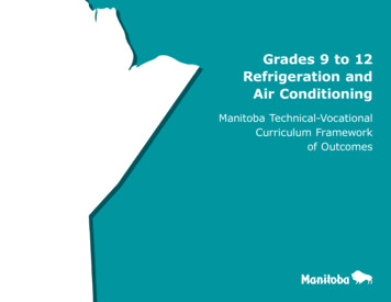
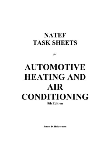
CHAROTAR UNIVERSITY OF SCIENCE & TECHNOLOGYFACULTY OF TECHNOLOGY & ENGINEERINGCHAMOS Matrusanstha Department of Mechanical EngineeringPlot the cycle on P-h chart as shown & find outHei Hco Hei Heo R.E. theo Heo - HeiCw theo Hei –HeoC.O.P. theo Heo – Hei / Hei –Heo 5. CARNOT C.O.P.For the cycle operating between the saturation temperatures of TH and T L, where TH and TLare saturation temperatures in K, corresponding to condensing and evaporating pressuresrespectively,COP (carnot) T L / (TH – TL) 6. MASS FLOW RATE OF REFRIGERENTLiquid refrigerant flow, Q LPHFrom table of properties of R-12 find v, specific volume of liquid at condensing pressureMass flow rate –m Q / (1000 x v) kg / hr7. THEORETICAL REFRIGERATING EFFECTRE Theo m (Heo – Hei) kJ/s (kW) 8. CAPACITY OF THE SYSTEMP R.E. / 3.5 Tons of refrigeration9. VOLUMETRIC EFFICIENCY OF COMPRESSORCompressor swept volume is V2 2.18 m3/ hrVolume discharged by compressor is V1 m3/ hrV1 m VsWhere, m mass flow rate Vs sp. Volume of vapour at suction (evaporation) pressure
CHAROTAR UNIVERSITY OF SCIENCE & TECHNOLOGYFACULTY OF TECHNOLOGY & ENGINEERINGCHAMOS Matrusanstha Department of Mechanical EngineeringTHERMODYNAMIC PROPERTIES OF R-12
CHAROTAR UNIVERSITY OF SCIENCE & TECHNOLOGYFACULTY OF TECHNOLOGY & ENGINEERINGCHAMOS Matrusanstha Department of Mechanical EngineeringConclusion:Marks obtained:Signature of faculty:Date:
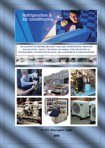
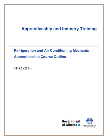
CHAROTAR UNIVERSITY OF SCIENCE & TECHNOLOGYFACULTY OF TECHNOLOGY & ENGINEERINGCHAMOS Matrusanstha Department of Mechanical EngineeringRefrigeration and Air-Conditioning (ME307)Date:Experiment No 3Cascade RefrigerationAIM: STUDY OF CASCADE REFRIGERATION SYSTEM FOR PRODUCING LOWTEMPERATURE.OBJECTIVES:1. To study Cascade refrigeration system.2. Comparison of VCRS and Cascade Refrigeration System.3. Advantages of Cascade Refrigeration System over Compound Compression Systemand VCRS.THEORY:Cascade refrigeration system is the extension of VCRS for producing low temperature whichis the main constrain in VCRS. In a cascade system a series of refrigerants with progressivelylower boiling points are used in a series of single stage units. The condenser of lower stagesystem is coupled to the evaporator of the next higher stage system and so on. The componentwhere heat of condensation of lower stage refrigerant is supplied for vaporization of next levelrefrigerant is called as cascade condenser. Figures show the schematic and P-h diagrams of atwo-stage cascade refrigeration system. As shown, this system employs two different refrigerantsoperating in two individual cycles. They are thermally coupled in the cascade condenser. Therefrigerants selected should have suitable pressure-temperature characteristics. An example ofrefrigerant combination is the use of carbon dioxide (NBP -78.4 0C, Tcr 31.06 0C) in lowtemperature cascade and ammonia (NBP -33.33 0C, Tcr 132.25 0C) in high temperaturecascade. It is possible to use more than two cascade stages, and it is also possible to combine multistage systems with cascade systems.a.b.c.d.APPLICATION OF THE CASCADE REFRIGERATION SYSTEM.Liquefaction of petroleum vapourLiquefaction of industrial gasesManufacturing of dry iceDeep freezing
CHAROTAR UNIVERSITY OF SCIENCE & TECHNOLOGYFACULTY OF TECHNOLOGY & ENGINEERINGCHAMOS Matrusanstha Department of Mechanical EngineeringBLOCK DIAGRAM and P-h CHART OF CASCADE REFRIGERATION SYSTEM
CHAROTAR UNIVERSITY OF SCIENCE & TECHNOLOGYFACULTY OF TECHNOLOGY & ENGINEERINGCHAMOS Matrusanstha Department of Mechanical EngineeringCONCLUSION:QUESTIONS:1. Comparison of cascade refrigeration system with VCRS andCompression.2. Explain 2 stage cascade refrigeration system by block diagram and p-h diagram.3. Applications of cascade refrigeration system.Marks obtained:Signature of faculty:Date:Compound
CHAROTAR UNIVERSITY OF SCIENCE & TECHNOLOGYFACULTY OF TECHNOLOGY & ENGINEERINGCHAMOS Matrusanstha Department of Mechanical EngineeringRefrigeration and Air-Conditioning (ME307)Date:Experiment No 4Vapor Absorption Refrigeration System.AIM:TO STUDY TWO TYPES OF VAPOR ABSORPTION REFRIGERATIONSYSTEM.1. NH3-H2 O2. LiBr-H2OOBJECTIVES:1. To study different components and working of Vapor Absorption RefrigerationSystem.2. To compare the cycle with VCRS.3. Study of actual vapor absorption system and its components.THEORY:Some liquids like water have great affinity for absorbing large quantities of certain vapors(NH3) and reduce the total volume greatly. The absorption refrigeration system differsfundamentally from vapour compression system only in the method of compressing therefrigerant. An absorber, generator and pump in the absorption refrigerating system replacethe compressor of a vapour compression system. Ammonia vapour is produced in thegenerator at high pressure from the strong solution of NH3 by an external heating source.The water vapour carried with ammonia is removed in the rectifier and only the dehydratedammonia gas enters into the condenser. High pressure NH 3 vapour is condensed in thecondenser. The cooled NH3 solution is passed through a throttle valve and the pressure andtemperature of the refrigerant are reduced below the temperature to be maintained in theevaporator. The low temperature refrigerant enters the evaporator and absorbs the requiredheat from the evaporator and leaves the evaporator as saturated vapour.Slightly superheated, low pressure NH3 vapour is absorbed by the weak solution of NH 3 whichis sprayed in the absorber in Weak NH3 solution (aqua-ammonia) entering the absorberbecomes strong solution after absorbing NH3 vapour and then it is pumped to the generatorthrough the heat exchanger.The pump increases the pressure of the strong solution to generator pressure. The strong NH3solution coming from the absorber absorbs heat form high temperature weak NH3 solution in theheat exchanger. The solution in the generator becomes weak as NH 3 vapour comes out of it.The weak high temperature ammonia solution from the generator is assed to the heat exchangerthrough the throttle valve.The pressure of the liquid is reduced to the absorber pressure by the throttle valve. LiBrH2 O system is somewhat different than aqua-ammonia based VARS. Water-Lithium Bromide
CHAROTAR UNIVERSITY OF SCIENCE & TECHNOLOGYFACULTY OF TECHNOLOGY & ENGINEERINGCHAMOS Matrusanstha Department of Mechanical Engineering(H2O-LiBr) system is for above 00C applications such as air conditioning. Here water is therefrigerant and lithium bromide is the absorbent.QUESTIONS:1. State the working principle of vapor absorption refrigeration system with neat sketch.2. Draw the schematic diagram of simple vapor absorption refrigerationsystem and state its limitations.3. Draw schematic diagram of actual aqua-ammonia refrigeration system and explain.4. Explain LiBr-H2 O system with neat sketch. And state itsadvantages/applications over aqua-ammonia.5. In a vapor absorption system, the heat is supplied to the generator by condensing steam by at 3bar and 85% dry. The temperature in the evaporator is to be maintain at -10oC. If the coolingwater reject heat at 30oC in a condenser, find the maximum C.O.P. of the system.6. In a 100 TR aqua ammonia abortion plant, saturated liquid ammonia at 30oC leaves thecondenser and enter the expansion valve. The evaporator pressure is 1.9 bar and the vaportemperature exit is -10oC. The mass concentration of ammonia in the weak and strong solutionare 0.25 and 0.325 respectively. Determine the mass flow rate (in kg/min) of the strong and weaksolutions.7. The following data refers to a lithium bromide water absorption refrigeration system.Capacity 2TR; Concentration of LiBr and enthalpy values for weak solution leaving generator .68 and 21 kJ/kg respectively. Temperature of water leaving condenser 40 oC; enthalpy ofsteam leaving evaporator 2508 kJ/kg; Specific heat of water 4.2 kJ/kg K. Determine themass flow rates of strong and weak solutions in kg/min and the heat transfer rates in generatorand absorber in kJ/min.CONCLUSION:Marks obtained:Signature of faculty:Date:
CHAROTAR UNIVERSITY OF SCIENCE & TECHNOLOGYFACULTY OF TECHNOLOGY & ENGINEERINGCHAMOS Matrusanstha Department of Mechanical EngineeringRefrigeration and Air-Conditioning (ME307)Date:Experiment No 5Psychrometric terms and Processes.AIM: TO STUDY OF DIFFERENT PSYCHROMETRIC TERMS AND PROCESSES.OBJECTIVES:1. To understand different terms related with air properties.2. Importance of different temperatures for the Psychrometric process.3. Study of different Psychrometric processes likea) Sensible cooling/heatingb) Latent cooling/Heatingc) Cooling and dehumidificationd) Heating and humidificatione) Evaporative coolingTHEORY:In the design and analysis of air conditioning plants, the fundamental requirement is to identifythe various processes being performed on air. Once identified, the processes can be analyzed byapplying the laws of conservation of mass and energy. All these processes can be plotted easilyon a Psychrometric chart. This is very useful for quick visualization and also for identifying thechanges taking place in important properties such as temperature, humidity ratio, enthalpy etc.The important processes that air undergoes in a typical air conditioning plant are discussedbelow.Important Psychrometric processes:a) Sensible cooling:During this process, the moisture content of air remains constant but its temperature decreases asit flows over a cooling coil. For moisture content to remain constant, the surface of the coolingcoil should be dry and its surface temperature should be greater than the dew point temperatureof air. If the cooling coil is 100% effective, then the exit temperature of air will be equal to thecoil temperature. However, in practice, the exit air temperature will be higher than the coolingcoil temperature.b) Sensible heatingDuring this process, the moisture content of air remains constant and its temperature increases as itflows over a heating coil.c) Cooling and dehumidificationWhen moist air is cooled below its dew-point by bringing it in contact with a cold surface, some of thewater vapor in the air condenses and leaves the air stream as liquid, as a result both the temperatureand humidity ratio of air decreases as shown. This is the process air undergoes in a typical airconditioning system. Although the actual process path will vary depending upon the type of coldsurface, the surface temperature, and flow conditions, for simplicity the process line is assumed to bea straight line. The heat and mass transfer rates can be expressed in terms of the initial and finalconditions by applying the conservation of mass and conservation of energy equations.
CHAROTAR UNIVERSITY OF SCIENCE & TECHNOLOGYFACULTY OF TECHNOLOGY & ENGINEERINGCHAMOS Matrusanstha Department of Mechanical Engineeringd) Heating and Humidification.During winter it is essential to heat and humidify the room air for comfort. This is normally done byfirst sensibly heating the air and then adding water vapour to the air stream through steam nozzles.e) Cooling & humidification.As the name implies, during this process, the air temperature drops and its humidity increases, this canbe achieved by spraying cool water in the air stream. The temperature of water should be lower thanthe dry-bulb temperature of air but higher than its dew-point temperature to avoid condensation (T T DPT TO ).f) Heating and de-humidificationThis process can be achieved by using a hygroscopic material, which absorbs or adsorbs the watervapour from the moisture. If this process is thermally isolated, then the enthalpy of air remains constant,as a result the temperature of air increases as its moisture content decreases. This hygroscopic materialcan be a solid or a liquid. In general, the absorption of water by the hygroscopic material is anexothermic reaction, as a result heat is released during this process, which is transferred to air and theenthalpy of air increases.QUESTIONS:1. Explain the following terms in brief. DBT,WBT,DPT2. Explain the different Psychrometric processes by Psychrometric chart.3. The atmospheric conditions of air are 350C dry bulb temperature, 60% relative humidityand 1.01325 bar pressure. If 0.005 kg of moisture per kg of dry air is removed, thetemperature becomes 250C. Determine the final relative humidity and dew pointtemperature.4. The atmospheric air at 150C dry bulb temperature and 80% relative humidity is suppliedto the heating chamber at the rate of 100 m3/min. The leaving air has temperature of 220Cwithout change in its moisture content. Determine the heat added to the air per min andfinal relative humidity of the air.5. 100m3 of air at 350C and 70% relative humidity is cooled to 200C and 55% relativehumidity by passing it through a cooling coil. Using psychometric tables only, find: 1.Theamount of water vapour removed in kg/h; and 2.The cooling capacity of the coil in tonnesof refrigeration. Assume specific heat of superheated vapour in air as 1.88 kJ/kg K and Rfor air 287.14J/kg K.6. The outside air at 310C dry bulb temperature and 18.50C wet bulb temperature enters acooling coil at the rate of 40 m3/min. the effective surface temperature of the cooling coilis 4.50C and its cooling capacity is 12.5kW of refrigeration. Find (a) dry bulb temperaturesof the air leaving the coil, (b) enthalpy of air leaving the coil, (c) by pass factor of the coil.CONCLUSION:Marks obtained:Signature of faculty:Date:
CHAROTAR UNIVERSITY OF SCIENCE & TECHNOLOGYFACULTY OF TECHNOLOGY & ENGINEERINGCHAMOS Matrusanstha Department of Mechanical EngineeringRefrigeration and Air-Conditioning (ME307)Date:Experiment No 6General Cycle Air Conditioning TrainerTHEORYAir conditioning is making the environment conditions suitable for various applications, like toproduce comfortable conditions at home, or to make more complete control of manufacturingprocesses in industries etc. a complete air conditioning system cleans the air, cools in summerand heats in winter, humidifies in winter and dehumidifies in summer and circulates it throughthe space where it is required. All the systems may not be equipped with all these controls. Thisunit is designed to study the basic processes of heating, cooling dehumidification andhumidification.THE APPARATUSThe unit consists of a duct, in which air flow is generated by an axial flow fan. A cooling coil,air heaters, and a steam injector are fitted in the duct. Adjustable flappers are provided in ductto control the air flow. At reduced flow rates of air, cooling coil can be used as dehumidifier.The condensing unit and steam, generator is located below the air flow duct. The hermeticcompressor compresses the refrigerant vapour and sends it to condenser, where it is liquefied.The liquid refrigerant is throttled by expansion valve to low pressure and temperature. This lowtemperature refrigerant goes to evaporator where it boils by collecting heat. The low pressurerefrigerant vapour coming from the evaporator is sucked by the compressor and again circulatedthrough the system.A steam generator with electrical heater is provided below the duct, which connected to steaminjector in the duct. The steam injection is controlled by a valve. Various measurements areprovided so different processes of air conditioning can be studied.SPECIFICATIONSCompressor – 0.6 ton (approx.) capacity, hermetically sealed, using refrigerant R-22(Monochlorodifluoromethane).Finned tube condenser with fan.Capillary tube.Finned tube direct expansion evaporator fitted in a duct of cross section of 250 x 250 mm.Fan to generate the air flow over the evaporator coil.Steam generator with electrical heater and steam injector.Heaters in the duct.Measurement and controls.Thermometers for cooling cycle and dry/wet bulb air temperatures.
CHAROTAR UNIVERSITY OF SCIENCE & TECHNOLOGYFACULTY OF TECHNOLOGY & ENGINEERINGCHAMOS Matrusanstha Department of Mechanical EngineeringEnergy meter’s for compressor and heater input-02 nos.Pressure gauges to measure condensing and evaporating pressures.High/low pressure output.Necessary switches.Flow control flappers in the duct.TERMINOLOGYDry air- It is a mixture of constituent gases which comprise the atmospheric air, excludingwater vapour.Moist air- It is the mixture of dry air and water vapour. Generally atmospheric air is moist air.Humidity – Water vapour that is mixed with atmospheric air is called humidity.Specific Humidity- It is mass of water vapour in moist air, expresses in Kg / Kg of dry air.Absolute Humidity – It is mass of ware vapour contained in a volume of air and is expressed ingrams per m3of air.Relative Humidity – It is the ratio of weight of water vapour contained in air at giventemperature in a given space to the maximum amount (mass) of water vapour that the air wouldcontain at the same temperature and volume, when fully saturated.Saturated Vapour – When air – water vapour mixture contains maximum amount of watervapour it can hold, it is called saturated. When temperature of mixture is above saturationtemperature, the vapour is supersaturatued.Dalton’s Low – In a mechanical mixture of gases, total pressure of the mixture is the sum ofpartial pressures of gases that each gas would exert when occupied the same volume at the sametemperature as that of the mixture.Dry Bulb Temperature – It is the temperatu
air-conditioning trainer. 7 Study of different air-conditioning systems. 8 Design of Air Conditioning System and load calculation for residential and commercial buildings. 9 Study and Performance on Sling psychrometer. 10 Exhaust gas heat recovery type VAR system. 11 Study of measurement devices of all experimental set-ups used in RAC laboratory.