Transcription
FlowCADFloWare ModulesProduct Description
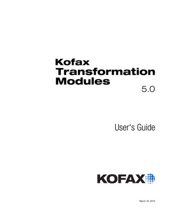
FloWare Add-OnsFlowCADFloWare Add-OnsIntegrated menu in OrCAD / Allegro PCB Editor for FloWare Modules2FloWare ModulesPCB Editor from OrCAD and Allegro includesa programming language (SKILL) which makesit possible to program customized add-ons forclients. FlowCAD offers a selection of functionsas FloWare modules which were created tomeet the specific needs of our customers.If you wish to integrate additional functionsinto PCB Editor yourself using these openprogramming interfaces, SKILL programmingcourses are offered at the Cadence TrainingCenter. If you prefer, the FlowCAD team canprogram additional functions to meet yourspecific needs for you.Installation of FloWare modules is a simpleprocess and does not require any expertknowledge. There is an installer, which copiesthe required files into the right folders. Theinstallation process includes a wizard andguides you through the FloWare installationprocess.The menu structures are automatically recognized by PCB Editor and shown in the tool bar.All FloWare modules are downloadable andthe license is distributed by e-mail. The licenseis valid for the site of your company location.A detailed PDF file documents the functionalityand is included with delivery.The following modules are currently available: Advanced Mirror Advanced Testpoint Check AOI Check Assign Net to Via (Change Net) Barcode Generator Batch Plot CAF-DRC Change Width Class ColorCleanliness CheckCoil DesignerCross CopyCross Section GeneratorCustom VariablesDesign CompareDrafting UtilitiesDrawing DesignerDrawing SizeDrawing View ManagerEdge PlatingFPGA UtilitiesHighlight Dummy PinsIBIS Prototype ModelerLabel GeneratorLabel TuneMask GeneratorNC Panel RouteNet Color ViewPadstack FinderPadstack UsagePanelizationPCB Library PlotPolar Grid UtilitiesPost ProcessingPush to GridQuick Symbol EditReplace ViaShape UtilitiesShield GeneratorShield RoutingSilkscreenSnap GeneratorSVG ExportSynchronize TestprepVariant 3DVariant AssemblyVariant BOMZ-DRC
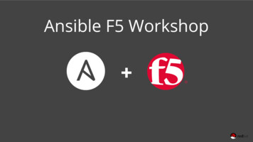
Advanced MirrorAdvanced Mirror is an application that allows users to perform mirror operations while movingor copying a group of selected objects. Mirroring can be performed either across subclasses or onthe same subclass (Geometry only). When wires and components are mirrored, DRCs will occurbecause the component pins no longer match the mirrored layout. Many users consider this newconnection of the pins to be much easier than rebuilding the complete circuit board. It is oftenused to mirror keepouts and shapes.Enables mirror operationsAdvanced Testpoint CheckIn order to optimally fulfill contacting requirements for In-circuit tests (ICT) various test probesare available. These differ in terms of height, size, tip style and type of connection. On the PCBthe corresponding contact areas (testpoints) must reflect these requirements. Advanced TestpointCheck is a toolbox application which addresses various rules for testpoint checking.Addresses various rules for testpoint checkingAOI CheckThis FloWare module helps users to check AOI related rules directly in PCB Editor. Shadowingcan cause serious issues in verification process. Shadows can be calculated in various directionsbased on specified camera angles (all, horizontal, vertical, 45 degrees) taking component heightinto account. Special rules apply to 3D inspection systems.Helps users to check AOI related rulesAssign Net to ViaAssign Net to ViaWhile working on a PCB layout in OrCAD PCB Editor or Allegro PCB Editor it happens, that youplace a via with no connection to a net. There are several reasons for this scenario, maybe youwant to use the via as a testpoint and the placement is predefined by the already existing testadapter or you have other reasons for the placement driven from the mechanical design. Withthe FloWare module Assign Net to Via you can assign easily any net to the stand alone via. Ifyou now start routing from the via, it already has the net information and will respect assignedconstraints.Barcode GeneratorBarcodes in PCB EditorTo identify PCBs some customers print barcodes on a PCB layer as part of the manufacturingprocess. With this FloWare module you can easily enter the value and create the barcode of thatvalue. The barcode is placed onto any layer of the design. The app supports symbol definitions forCode 39, Code 128, QR Code and DataMatrix with adjustable parameters for barcode height,width, single bar width and margins. You have the choice, if you want to show the text underthe bars or choose an inverted display. For easy dimensioning you have a dynamic preview duringparameter change.Batch PlotIn order to automate production data output (Gerber data, drill plans, ) it is advisable to createa defined document batch. The FloWare module Batch Plot supports this function. The user cancreate a whole batch of data in one step as a PDF file. You write the data using a PDF print driver(e.g. Adobe Acrobat) in one or more multi-page documents. The order of the pages in the databatch can be defined by the user. The settings for complete document batches for production,assembly and tests are saved.Defining output data as a batch file3
FloWare Add-OnsCAF-DRCCAF (Conductive Anodic Filament) describes the chemical effect of copper ion migration in theFR-4 base material at high voltages, which causes breakdowns in the printed circuit board. TheFloWare module CAF-DRC makes it possible to execute a special design Rule Check in the PCBEditor for OrCAD and Allegro. The corresponding minimum distances between the bore outerdiameter and the next conductive material are specified as a function of voltage classes. If thedistance is undercut, a DRC error occurs.Special DRC for CAF on PCBsChange WidthChange Width helps users to change the width of clines and clines segments. In contrast tothe standard “Edit – Change” command this module supports a filter mechanism in that thechanges are only applied to segments matching a given width. Furthermore highlight and reportfunctionality is available. Users can select by pick, window, temp group or find by name.Change the width of clines and clines segmentsClass ColorWith this FloWare module for OrCAD and Allegro PCB Editor you can colorize different nets. Thisis helpful, when you have high voltages on the PCB and you have to ensure a certain net spacingbetween several net classes for isolation. When coloring each voltage range in one color, you canvisually review your design rules and identify missing or wrong design rule settings. This featurehelps you when reviewing a design or need to document spacing classes.Nets colored by classCleanliness CheckCleanliness Check analyzes the PCB layout for contact areas caused by particles with a given size.Contact area specifies the area in which a particle will cause a short, no matter how the particleis oriented. Cleanliness Check calculates and visualizes contact areas using shapes and writes areport. By sweeping the particle size the information from the output can be used to feed cleanliness assessment calculator from ZVEI.Cleanliness Check calculates and visualizes contact areasCoil DesignerGenerate planar PCB windingsWith FloWare module Coil Designer you can quickly create planar windings for transformers in PCBEditor. The generation is controlled with variable parameters. Available are four general shapes:round, rectangular, hexagonal and octagonal. With changes in the parameters in the menu thedimensions or number of windings will be dynamically updated in the preview at the cursor. Cornerscan be mitered or rounded off with a parameterized radius. Within a structure a keep out area canbe generated as well with a spacing towards the inner winding. If you want to place a via at thebeginning and end of the winding, you can select an available via type. Winding direction can beclockwise or counterclockwise and the geometry can be rotated.Cross CopySome users wish to expand the copy function of PCB Editor. Using the command Edit-Copyin Cross Copy, a target layer can be defined. Standard copy command does not support adestination layer and compared to the Z-Copy command, Cross Copy offers way more flexibility.Merging data to soldermask shape4
Cross Section GeneratorSVG Export, e.g. for documentation purposesFor documentation purpose the cross section (PCB stack up) needs to be documented. This modulecreates a documentation view of the cross section which is stored in the PCB Editor database.The appearance is customized for the content, which might include: layer name, layer thickness(including total thickness), layer material, via stack and via labels. Various graphical options canbe set up like symbol size (extra row column spacing), fill styles for conductor and dielectrica,scaling of layer thickness for better readability. The configuration of the appearance is stored inthe database and an updated plot will be generated without entering all settings.Custom VariablesIn PCB Editor the user can define his own variables to be used in the title block or as etch text. Thevariables are automatically updated across all subclasses and a placeholder can reference to morethan one variable. The placeholder attributes (x, y, block, rotation) are stored in the database. Thevalues for the variables can be entered manually, sourced from an external control file or evena cpm-file. Special fields are available for inserting Auto Date, Auto User, and others.Managing custom variables like date, user, .Design CompareDesign Compare compares two design databases and recognizes the differences. In this waydeviations in the product life cycle can be detected and documented. The application distinguishesdesigns in two different types of comparison. In the standard comparison, parameters in thedesign that exist as numbers or texts (e.g., net names, properties) in the database are compared.In addition, a graphical comparison of the geometry of the layout is possible. The results can beoutput as an HTML report.Useful when tracking changes in the product lifecycleDrafting UtilitiesWhen you need to manipulate geometric forms you normally can do the operations much easierin a mechanical CAD software compared to OrCAD PCB Editor or Allegro PCB Editor. But FloWaremodule Drafting Utilities offers some useful functions to edit geometric PCB forms. It is possibleto cut through forms and structures and use the separated individual pieces. This helps to createunusual shapes which are not based on a grid but on intersections of other objects. Besides thecutting feature there are some useful drawing features for lines and arcs.Cutting a bus in three segmentsDrawing DesignerDrawing Details for ManufacturingManufacturing departments often need a zoomed area of a PCB for a detailed view of a specialarea. In PCB Editor you can create such a drawing detail. But FloWare module Drawing Designeroffers more functionality. Details can be created on an additional documentation layer with adefined zoom factor and are always in synchronization with the electrical layers of the basedesign. Created details can be rotated or mirrored on documentations layers and the synchronization is done automatically. Settings are stored in the design database and are available whenthe design was opened. Settings can also be exported for usage in other designs.Drawing SizeThe FloWare module Drawing Size allows users to change and modify the drawing extents ina quick and easy way. This is useful if you want to reduce design extents to minimum values.Settings can be applied to all or individual sides.Quick and easy way to change the design extents5
FloWare Add-OnsDrawing View ManagerWhen releasing a PCB design for production, additional documentation is required for manufacturing, assembly or testing. Drawing View Manager facilitates the creation of manufacturingdrawings. Scale factor or mirrored geometry, rotation and other parameters can be specified.Changes to the master PCB can be applied with a single click. User-defined templates simplifythe work.Easy creation of manufacturing drawingsEdge PlatingEdge plating and castellation used metallization at the sides of a PCB. It is used for EMI-shielding,thermal heat distribution as part of a cooling solution, better current distribution for powerelectronics, mechanical protection when the PCB slides in a ground connector or to solder a PCBdirectly on top of another PCB without a connector. The app supports two modes of operation,wraparound edge plating and castellated holes.Wraparound Edge PlatingFPGA UtilitiesWhen routing FGPAs on a circuit board, it is often necessary to swap individual pins (pin swap)to optimize routing. These changes must be saved in the FPGA environment so that the FPGAdesigner can synchronize his data. FPGA Utilities generates various reports for this purpose(e.g. Show Difference). Pin Constraints in manufacturer-specific formats (MicroSemi / Actel,Xilinx, Altera, Lattice or Excel / CSV) can also be generated which the FPGA tool can use directly.FPGA Utilities enables the user to synchronize FPGA and PCB design data quickly and efficiently.Reports for FPGA FlowHighlight Dummy PinsWith FloWare module Highlight Dummy Pins you can assign a color to each unconnected pin.In a report you can see all unconnected pins and walk them through one by one. Cross probingfrom the report will zoom in the pin in the design. This app is useful for reviews of a design andyou need to verify each unconnected pin, if it was unconnected intentionally or unintentional.Unconnected pins are highlightedIBIS Prototype ModelerCreates scalable IBIS models for early stage SI analysisWhile designing and simulating a new PCB, there are situations where simulation models fromcomponent vendors are not available yet. For this reason users may want to start with a linearmodel first with a given voltage swing and an adjustable internal resistance based on informationfrom datasheet. Creating an IBIS model from scratch using a text editor is time consuming anderror prone. IBIS Prototype Modeler is a Floware module that allows users to create linear IBISmodels on the fly for early stage simulation purposes in Sigxp. It offers all important features likethe ability to create Push / Pull, Open-Sink and Open-Source buffers, adjustable voltage levels, etc.Label GeneratorIn the documentation of circuit boards, it makes sense to name individual traces. With LabelGenerator text can be produced automatically through selection and stored on a layer for documentation purposes. Such text can then be hidden and unhidden. If necessary, text can be createdfrom the available information in the database. It is possible to depict the pin name, signal nameor combination of pin and signal name. The user positions text depending on selected objectsand can make adjustments assisted by reference lines.Documentation of traces in the layout6
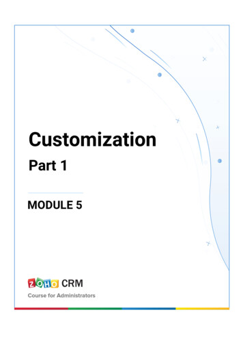
Label TuneThe positioning of reference labels in the library is normally standardized. After placement or inthe case of high-density designs, texts can become difficult to read. Manual adjustment of textparameters is then necessary. With Label Tune, label size, rotation, and position can be adjustedso that they are easier to read for Assembly Drawings. Further parameters are mirror and centerfit, which incorporate maximum block size and spacing to component boundaries.Adjustments to the labeling of componentsMask GeneratorIf you change your supplier for PCB fabrication, it might be necessary to change your masks sets.FloWare module Mask Generator offers additional features in OrCAD PCB Editor and Allegro PCBEditor to change (expand / contract) in a post process the mask data (i.e. solder mask and pastemask). The modified data will be stored on an additional documentation layer, so the base designstays unchanged.Oversized solder maskNC Panel RouteThis toolset supports various techniques for PCBs in a panel to be easily separated after they aremanufactured and assembled. It is possible to add mill contour, split and cut mill and to add milltabs with or without perforation drills. The app provides libraries from different PCB fabricators.V-Score lines can be defined in horizontal or vertical directions by selecting an appropriate side ofthe board. V-Score fabrication details can be specified which creates an IPC-2581 Spec Definitionentry in the database.V-Score Fabrication DetailsNet Color ViewNet Color View allows saving and restoring net color and rat visibility settings. This is very usefulfor floorplanning and route feasibility studies. Temporary colored nets for a special task areeasier to identify.Net Color ViewPadstack FinderWith FloWare Padstack Finder you can search in OrCAD PCB Editor or Allegro PCB Editor in thecurrent design for pad stacks and highlight them. It is differentiated, if the pad stack is a pin or avia. The highlighted results are also available in a report and can be zoomed in by cross probingfrom the report. Different colors can be assigned to groups for highlighting. The filters Pad stackname and Drill diameter are available.Different color per padstackPadstack UsagePadstack Usage module allows users to generate padstack reports by extracting data from PCBEditor symbol libraries (*.dra). Different reports output formatted text, MS Open XML, and HTML: Where-Used: A report which lists all footprints that use a given padstack. Padstack Standard: A report that lists the padstack definitions for a given footprint. Padstack Detailed: A report which lists detailed information for a given footprint. This information includes number of pins, vias and mechanical pins, pin numbers, xy coordinates etc.Report examples in formats HTML (left) and XML7
FloWare Add-OnsPanelizationPCB fabrication panelPCBs are manufactured often in fabrications panels. If the placement is not done by the externalmanufacturing company, the PCB designer can use the FloWare module Panelization to do ithimself. Just open a new blank project in PCB Editor and place a manufacturing frame andfiducials. Now you can place routed designs multiple times in the panel. The design data will belinked with x and y coordinates and rotation information. While placing a design on the panelyou can see the dimensions as a preview. Multiple placements of the design will automaticallyadd a defined prefix to each instance of the design to avoid naming conflicts (duplicates).PCB Library PlotCatalog of all footprints in a libraryDuring development electrical engineers would like to see which PCB footprints are available inthe company’s library. This module will process a complete library and create a PDF documentwith a graphical representation of all available footprints. The graphics will be scaled to fit intoa selected template (i.e. 4-up, 6-up, 8-up). In addition to the footprint attributes are added intoeach field, like footprint name, dimensions (place bound, visible), height, pitch, used pad stacks,pin count, mechanical pin count, etc. Which attributes are printed is customized. The add-on canrun through different libraries.Polar Grid UtilitiesIn some applications (e.g. medical, automotive) not only the boards have a circular outline alsoplacement and routing has to be done in a circular fashion. Doing these kinds of boards on thebasis of a cartesian grid is time consuming and cumbersome. Polar Grid Utilities is a toolkit that is exactly dedicated to this kind of application. Besides thecapability to define a polar grid, it offers additional functions such as polar placement, polarrouting and polar shapes including voids.Useful when circular placement and routing is requiredPost ProcessingDefining standard output jobsIf a company always orders their PCBs from the same manufacturer, the required manufacturingdata is also always the same. The FloWare module Post Processing offers a feature set to generatethe output in always the same way in OrCAD and Allegro PCB Editor. You can generate sets ofoutput data of existing reports in always the same order. Before you can run scripts or other SKILL(FloWare) routines to define parameter settings. The configuration will be saved in the databaseand the output job can be created with exactly the same settings. You can define in Post Processing different output jobs and start them individually. The created files can follow a namingconvention (wild cards, variables and pattern tags).Push to GridPush to Grid is a placement application that allows users to highlight off grid symbols includingan option to move / push them to the nearest grid point. Furthermore it supports a regular placement mode for standard placement operations.Placement applicationQuick Symbol EditShorten the Symbol Edit Flow in PCB Editor8FloWare module Quick Symbol Edit was developed for such users who want to speed up thelibrarian work flow. There are three typical use cases for this app in OrCAD PCB Editor or AllegroPCB Editor. At first there is a possibility to change a symbol in the same session, which is similarto the Modify Design Padstack handling. The second methodology is to open a new sessionwith a pre loaded Symbol.dra file. And finally you have the choice to export the symbol as .dra,.psm, .pad etc. in a specified directory. The file opening and closing will be handled by the appautomatically.
Replace ViaReplace Via is an application which gives users some more flexibility while replacing via padstacksin the design. The operation can be restricted to a selected area. Vias can be included andexcluded through interactive commands taking various filter criteria into account. Additionalprocessing options such as Ignore DRC or Retain Mirror Status are available.Select the vias to be exchangedShape UtilitiesModification of shapesCopper shapes have to have sometimes very specific outlines for electrical reasons to enable acircuit board to perform correctly. FloWare app Shape Utilities can efficiently enhance the existingfunctionality in OrCAD PCB Editor or Allegro PCB Editor. With boolean operations (OR, AND,ANDNOT, XOR) two shapes can be calculated against each other to a new shape. The originalshape attributes (shape type, fill style, net name, .) of the primary shape will remain attachedto the resulting shape. Any shape can also be scaled with size operators (Expand / Contract). Aseparate parameter will specify the handling of voids. Shapes with corners can be rounded off.Shield GeneratorShield Generator is a toolbox application which facilitates the generation of shape and via patternfor shielding purposes. This includes shield rings along board outline (e.g. for ESD protection)as well as generation of shield boxes for RF circuits which require additional noise reduction.The user can choose between different modes for shield generation and can set parameters forshape and via. Mask generation and cutting capabilities for solder mask and paste mask can alsobe used.Easy shape and via pattern generation for shielding purposesShield RoutingCreates shield for critical signals in a semiautomatic waySome RF applications require shields for critical signals in order to minimize crosstalk and noise.Shields may be realized on the same layer like the signal trace (side shield) or on adjacent layersabove or below the signal trace (tandem shield). In both cases the shield structure follows thestructure of the signal trace and is expanded to a certain extent. Usually shields are realized bydynamic or static shapes connected to a ground net. Route keepouts may be also understood assome sort of shielding as they keep noise away. Shield Routing is an application which enablesusers to create shields for signal traces inside PCB Editor.SilkscreenIf printed circuit boards are densely populated, it may happen that there are vias or other elements under the silkscreen that should not be overprinted. With the module Silkscreen DRCdesign rules can be defined. Based on these rules, the module analyzes the PCB design andoutputs corresponding errors according to the design rule check. The designer can decide if andhow these bugs are eliminated. The module deletes according to the settings specifically silkscreenat the desired locations.Silkscreen DRCSnap GeneratorSnap points for geometrical adjustmentsThe graphical editing of copper areas, pads or other geometrical forms is sometimes complexand goes beyond the standard functions of PCB Editor. With Snap Generator it is possible togenerate intersections of objects (I intersection), center points (C), end points (E), pins (P origin) or equally long sections (X section) by selecting the elements. The generated snap pointsare saved on a separate layer and their coordinates can be combined with normal commandsin PCB Editor. In this way, all special points outside the grid can be incorporated reliably andaccurately.9
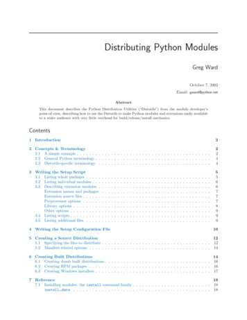
FloWare Add-OnsSVG ExportSVG Export is an application which allows users to generate SVG data out of PCB Editor. Userscan export SVG from current drawing, and for a complete footprint library (including HTM reportgeneration). Content and styles can be specified by using predefined profiles. SVG is a vector fileformat for pictures, which is small in size and displays well on screens, and print as sharp image.Generates SVG data out of PCB EditorSynchronize TestprepTest points synchronized with schematicThe FloWare module Synchronize Testprep can help in OrCAD PCB Editor or Allegro PCB Editor toassign a test point when using dummy test symbols (1-pin part with RefDes TP*) in the schematic.This app will generate from the schematic a corresponding test point in the PCB layout data base.Afterwards all PCB Editor post processing routines for test points (Testprep) can be used as usual.The menu offers various parameters to create a drawing detail. You can select the target layer,rotation, scale factor, and mirror. Pads can be filled or left unfilled and shapes can be displayedas they were defined in the design, unfilled, or hatched.Variant AssemblyCustomized assembly drawings for variantsThis module gives users more flexibility when creating variant assembly views. Production ofvariant views in one step is automated. Label content is customized (RefDes, Value, Part Number).The outline is also customized to assembly, place boundary, silk screen, or any other outlinefrom the data base. Different styles for DNI (do not install) components are provided: remove allcomponents, draw a thick cross through the label and many more styles. Alternate symbols canbe indicated with a modified label with prefix or suffix or different component outline line styleor hatched filling. In the output a automatic mirror for the bottom side can be placed.Variant BOMThis add-on creates various BOM reports (Bill of Material) from PCB Editor database takingexisting variant information into account. It can generate a pick and place report for each variantor the core design. The content is customized for any database attribute. Header information canbe added as well as selecting the number of columns and their order.All settings will be stored to easy regenerate the report after design modifications. The reportcan be generated in ASCII, HTML or CSV.Variant BOM user interfaceZ-DRCDRCs in PCB Editor work only in x and y direction. Z-DRC checks can be made respective thez-coordinates. This might be useful for safety or explosive requirements. The user can selectbetween which layers the check shall be performed. As a result a list of Z-DRCs will be displayed.By clicking on each Z-DRC PCB Editor will zoom in on the area, where the error was found. TheDRCs can be stored as external DRCs in the database.DRC for violations in Z-coordinates10
FloWare is available through your localCadence Channel Partner:DenmarkNordcad Systems A/SFranceARTEDAS FRANCEIsraelEDA Integrity Solutions Ltd.ItalyARTEDAS ITALYNetherlandsCB Distribution BVRussiaPCB SoftSwedenGATEline ABTaiwanGraser Technology Corp.UKParallel System LimitedUSAEMA Design Automation, Inc.FlowCAD11FlowCAD (Deutschland)FlowCAD (Schweiz)FlowCAD (Polska)Mozartstr. 285622 Feldkirchen bei MünchenGermanyHintermättlistr. 15506 Mägenwil (Aargau)Switzerlandul. Sa siedzka 2A80-298 GdańskPolandT 49 89 45 637 - 770F 49 89 45 637 - 790T 41 56 485 91 91F 41 56 485 91 95T 48 58 732 74 77F 48 58 732 72 FlowCAD.chinfo@FlowCAD.plwww.FlowCAD.plFlowCAD and the FlowCAD logo are registered trademarks of FlowCAD EDA-Software Vertriebs GmbH in Germany and / or other countries. All other brand names, productnames, or trademarks belong to their respective holders. FlowCAD reserves the right to alter product and services offerings, and specifications and pricing at any time withoutnotice, and is not responsible for typographical or graphical errors that may appear in this document. All rights reserved. 2022 FlowCAD EDA-Software Vertriebs GmbH
Defining output data as a batch file Batch Plot In order to automate production data output (Gerber data, drill plans, ) it is advisable to create a defined document batch. The FloWare module Batch Plot supports this function. The user can create a whole batch of data in one step as a PDF file. You write the data using a PDF print driver