Transcription
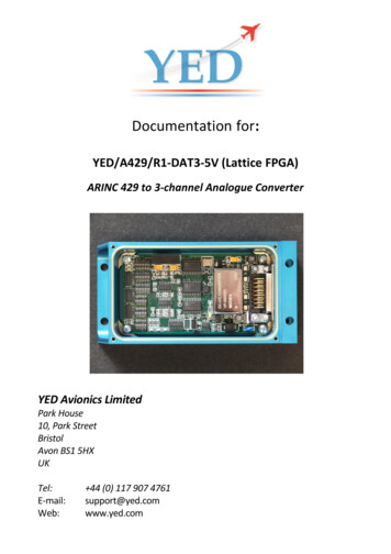
Documentation for:YED/A429/R1-DAT3-5V (Lattice FPGA)ARINC 429 to 3-channel Analogue ConverterYED Avionics LimitedPark House10, Park StreetBristolAvon BS1 5HXUKTel:E-mail:Web: 44 (0) 117 907 4761support@yed.comwww.yed.com
YED Avionics LimitedVersion 1.0Documentation for: YED/A429/R1/DAT3-5V ConverterAmendment PageVersion1.0Date of Issue27 Apr 2015Change ReferenceN/ARemarksOriginal IssueOriginal Author:G.S. BrownettDate of Origin:27th April 2015File Ref:A429-R1-DAT3-10V-Lattice.man.docFirmware Version: V1.0CONDITIONS GOVERNING THIS DOCUMENTATION1.Purpose of documentThe information for the YED/A429-R1-DAT3-5V is provided for purposes of supplying interfaceinformation for use by the end user.2.No Grant of Proprietary RightsNothing herein shall be construed as granting to the receiving party any proprietary rights or any licencein respect of YED’s proprietary information.3.ConfidentialityNo information contained herein shall be used, copied, re-transmitted to third parties or otherwisemade use of except for the express purpose defined above in the section covering the ‘Purpose ofdocument’.4.DisclaimerAll information, including illustrations, is believed to be reliable. Users however, should independentlyevaluate the suitability of the product for their particular application. YED Avionics Limited makes nowarranties as to the accuracy or completeness of the information, and disclaims any liability regardingits use. YED’s only obligations are those contained in the Standard Terms and Conditions of Sale for anyincidental, indirect or consequential damages arising from the sale, resale, use or misuse of the product.See http://www.yed.com/terms.php for more information.Information contained in this manual is subject to change without notice.
YED Avionics LimitedVersion 1.0Documentation for: YED/A429/R1/DAT3-5V ConverterCONTENTSCONDITIONS GOVERNING THIS DOCUMENTATION . 21INTRODUCTION . 41.11.21.3FIRMWARE. 5ENVIRONMENTAL, AIRWORTHINESS AND EMC . 5SPECIFICATION . 62CONFIGURATION OF CONVERTER . 82.12.22.32.42.52.6DESCRIPTION OF SETTING LABELS . 8LABEL SWITCH DESCRIPTION. 8SDI AND SSM SWITCH DESCRIPTION . 9ARINC 429 LABEL AND DATA WORD FORMAT. 9LED INDICATION SHOWING RECEPTION OF LABELS A, B AND C . 9LED INDICATION OF ARINC 429 BIT RATE . 103 CONNECTOR PIN OUT (D15 PLUG) . 104ENCLOSURE OUTLINE DRAWING . 125TYPICAL INTERCONNECT DRAWING . 136INSTALLATION. 146.1 ELECTRICAL CONSIDERATIONS . 146.2 MATERIALS NOT SUPPLIED . 146.3 MOUNTING CONSIDERATIONS. 146.4 WIRING . 146.5 REMOVAL AND REPLACEMENT . 146.5.1Removal . 146.5.2Replacement . 156.6 CONTINUED AIRWORTHINESS . 156.6.1Scheduled Maintenance . 157ENVIRONMENTAL & EMC . 168ANNEX 1 – EXPLOSIVE DECOMPRESSION TESTS . 17Page 3
YED Avionics LimitedVersion 1.0Documentation for: YED/A429/R1/DAT3-5V Converter1IntroductionThis manual contains specification data, installation and instructions for the YED/A429-R1-DAT35V, ARINC-429 to Analogue converter.The function of this converter is to monitor a single ARINC 429 data bus for three selected ARINC429 labels and to translate the value contained within bits 28 thru 17 into a 0 to 5V DC output.The ARINC 429 receiver is coupled to the data bus via an Optocoupler to maintain electricalisolation and EMI immunity.This converter consists of a single channel ARINC 429 receiver and decoder that drive three D/AConverters configured to give a 0-5V DC output for each of up to three received ARINC 429Labels. The three ARINC 429 Labels are selected by means of surface mounted switches on theprinted circuit board. When the specified labels are received the respective analogue outputchannel is updated to reflect the value contained in the received ARINC 429 data word. Theanalogue outputs are latched and will maintain the value of the last received data word until newdata is received.The converter can receive high or low speed ARINC 429 data automatically without userintervention. On the PCB there are two LED indicators that display the bit rate of the receivedARINC 429 as Hi or Lo bit rates. In addition there are three more LED indicators that indicatereception of the three selected ARINC 429 Labels.The unit is powered from an external 28 VDC (18-60V) nominal supply with internal current andthermal (102 ºC) fuse. The power inputs are also reverse polarity protected and incorporate allthe standard YED EMC/EMI surge protection techniques including a power supply monitoringdevice, which will cause the system to reset in the event of any problems with the main supply.A block diagram of the main components of the converter is shown overleaf.Page 4
YED Avionics LimitedVersion 1.0Documentation for: YED/A429/R1/DAT3-5V ConverterBLOCK DIAGRAM OF CONVERTER INTERNALS1.1FirmwareThis design is based upon a Field Programmable Gate Array (FPGA) only. There is nomicroprocessor and therefore RTCA DO-178 certification is not required for this product.1.2Environmental, Airworthiness and EMCThe YED/A429-R1-DAT3-5V Converter has been designed to meet DO-160D test categories listedlater in this manual.The unit has also been subjected to an Explosive Decompression test from 15,000 feet to 50,000feet in a period of less than 100mS without effect. See Annex 1.Page 5
YED Avionics LimitedVersion 1.0Documentation for: YED/A429/R1/DAT3-5V Converter1.3SpecificationThe YED/A429-R1-DAT3-5V has the following features: PhysicalThe YED/A429-R1-DAT3-5V attaches to the airframe via four mounting holes. See paragraphtitled “Enclosure Outline Drawing” for further details.The enclosure is a CNC machined box with Anodised and an Alocrom 1200 finish.Height . . .28.0mmWidth . . . .68.0mmLength . . . 136.0mmWeight . . . .300 grams (approx.)ElectricalInput Voltage . .Input Current . .Reverse polarity protected.Electrically fused Thermally fused .Indicators (on PCB)LED bit rate reception: LED Label reception: ARINC 429 InputNumber of receivers Input is via opto-coupler.Bit Rate .28V DC (15 to 60V DC operational)30mA maximum at 28V DC500mA (non-resettable)102 Degs. C. (non-resettable)Hi Speed/Low Speed3 LEDs. Label A, B & C.112.5kHz or 100kHz. (auto detecting)Analogue outputsNumber of Analogue outputs Channel 1 output . .Channel 2 output . .Channel 3 output . .Bit field of interest .3Channel 1 DC output, 0-5V DCChannel 2 DC output, 0-5V DCChannel 3 DC output, 0-5V DC28.17ARINC 429 Labels filtered (Any 3 from 256)Channel 1: .Channel 2: .Channel 3: .User selectable Label via SMD switchesUser selectable Label via SMD switchesUser selectable Label via SMD switchesPage 6
YED Avionics LimitedVersion 1.0Documentation for: YED/A429/R1/DAT3-5V ConverterARINC 429 SSM and SDI filteringSSM filtering for channels 1,2 & 3: .SDI filtering for channels 1,2 & 3: . .11,10,01,00 or XX (Don’t care) via SMD switches11,10,01,00 or XX (Don’t care) via SMD switchesConnectorIndustry Standard D15 sub-miniature socket.EnvironmentalOperating temperature range . . -40 to 85 degrees C.Page 7
YED Avionics LimitedVersion 1.0Documentation for: YED/A429/R1/DAT3-5V Converter22.1Configuration of converterDescription of setting LabelsThe values of each of the Labels are set by the adjusting the surface mounted DIP switches on thePCB as shown below.LABEL A is set to 320LABEL B is set to 324LABEL C is set to 325LABEL A SDI 00LABEL A SSM 11LABEL B SDI 00LABEL B SSM 11LABEL C SDI 00LABEL C SSM 112.2Label switch descriptionLabels are coded in Octal.Red spot denotes a switch set to 4LAB-L3ONONPage 8LAB-L2LAB-L1ONLABEL320324325
YED Avionics LimitedVersion 1.0Documentation for: YED/A429/R1/DAT3-5V Converter2.3SDI and SSM switch descriptionThe SDI and SSM switch is coded as shown NONDON’TCARESDI-10 refers to Bit 10 of the ARINC 429 wordSDI-11 refers to Bit 11 of the ARINC 429 wordSDI- Don’t care means ignore SDI-10 and SDI-9 settings.SSM-31 refers to Bit 31 of the ARINC 429 wordSSM-30 refers to Bit 30 of the ARINC 429 wordSSM- Don’t care means ignore SSM-31 and SSM-30 settings.Don’t care mean that there will not be any filtering of the respective SDI and/or SSM fields.2.4ARINC 429 Label and data word formatA typical ARINC 429 data word is shown below. Starting at Bit-32 is PARITY Bits 31 & 30 are the SSM filed, which indicates the status of the data.Bit-29 is the sign bit of the data.Bits28 thru 9 is the data field for this type of data word. Note that the SDI field on bits 10 & 9 isnot present for this particular data word.The Label field shown here as 076. Page 9
YED Avionics LimitedVersion 1.0Documentation for: YED/A429/R1/DAT3-5V Converter2.5LED indication showing reception of Labels A, B and CThe image below shows the area of the printed circuit board that contains Label reception statusLED indicators. If an LED is lit then the label is being received and decoded.LABEL A2.6LABEL BLABEL CLED indication of ARINC 429 bit rateThe bit rate of the received ARINC 429 data can be identified by inspection the LEDs as shown below.HIGH SPEEDLOW SPEEDPage 10
YED Avionics LimitedVersion 1.0Documentation for: YED/A429/R1/DAT3-5V Converter3 Connector Pin Out (D15 Plug)The YED/A429-R1-DAT3-5V contains a single 15-pin filtered male connector, J1, per MIL-C24308.PinSignalFunction123 28V DC0V GroundA429 Rx VePrimary power28V DC ReturnARINC 429 Receive (input) RXA45A429 Rx -VeA429 Ground (0V)ARINC 429 Receive (input) RXBARINC 429 Screen (Shield)6CH1 : 5V O/PChannel 1, Label A, 0 5V DC output789101112131415CH1: 0V O/PCH2 : 5V O/PCH2: 0V O/PCH3 : 5V O/PCH4: 0V O/PReservedReservedReservedReservedChannel 1 ground / 0V output.Channel 2, Label B, 0 5V DC outputChannel 2 ground / 0V output.Channel 3, Label C, 0 5V DC outputChannel 3 ground / 0V output.ReservedReservedReservedReservedTable 1 – J1 Pin DescriptionPage 11
YED Avionics LimitedVersion 1.0Documentation for: YED/A429/R1/DAT3-5V Converter4Enclosure outline drawingAll dimensions are in mm.Page 12
YED Avionics LimitedVersion 1.0Documentation for: YED/A429/R1/DAT3-5V Converter5Typical interconnect drawingA typical equipment interconnect wiring diagram is shown below.Page 13
YED Avionics LimitedVersion 1.0Documentation for: YED/A429/R1/DAT3-5V Converter6InstallationThis section provides details for the installation of the YED/A429-R1-DAT3-5V Converter,including configuration and mounting procedures. Follow the procedures and recommendationsfound in this section to assure a successful installation.6.1Electrical considerationsA circuit breaker such as a Klixon 7277-2-1 or equivalent should be considered for connectingthe power from the aircraft supply to this converter – even though the converter is internallyfused.6.2Materials not supplied 6.3Wire: MIL-W-22759/16 or equivalentShielded wire: MIL-C-27500 or equivalentMounting Screws, 4 each.Mounting considerationsThe YED/A429-R1-DAT3-5V can be mounted in the avionics bay, shelf or other suitablestructure. It can be mounted in any orientation.6.4WiringUse 22 to 24 AWG wire for all connections.Fabricate wiring harness, and test all wiring for continuity and for shorts. Ensure aircraft poweris present on the correct pins of J1; refer to Table 1.6.5Removal and replacement6.5.1 Removal1. Open the circuit breaker powering the YED/A429-R1-DAT3-5V.2. Remove the connector.3. Remove four (4) screws securing the converter to the airframe.Page 14
YED Avionics LimitedVersion 1.0Documentation for: YED/A429/R1/DAT3-5V Converter6.5.2 Replacement1. Open the circuit breaker powering the YED/A429-R1-DAT3-5V2. Secure the converter to the airframe with four (4) screws.3. Attach the connector and secure4. Close the circuit breaker.5. Perform operational test of the YED/A429-R1-DAT3-5V6.6Continued Airworthiness6.6.1 Scheduled Maintenance Recommended periodic scheduled servicing . NoneRecommended periodic scheduled preventativemaintenance tests . . NoneRecommended periodic inspections . NoneRecommended period overhaul period . NoneSpecial inspection requirements . NoneThere are no Airworthiness limitations associated with the installation of this converter.Page 15
YED Avionics LimitedVersion 1.0Documentation for: YED/A429/R1/DAT3-5V Converter7Environmental & EMCThe YED/A429-R1-DAT3-5V has been designed to meet the environmental test categoriesdetailed below in accordance with RTCA DO-160D, Environmental Conditions and TestProcedure for Airborne Equipment.Section4.0 Temperature and Altitude5.0 Temperature and variation6.0 Humidity7.0 Operational Shock and Crash Safety8.0 Vibration9.0 Explosion Proofness10.0 Waterproofness11.0 Fluids susceptibility12.0 Sand and Dust13.0 Fungus Resistance14.0 Salt Spray15.0 Magnetic Effect16.0 Power Input17.0 Voltage Spike18.0 AF Conducted Susceptibility –Power Inputs19.0 Induced Signal Susceptibility20.0 Radio Frequency Susceptibility(Radiated and Conducted)21.0 Emission of Radio FrequencyEnergy22.0 Lightening Induced TransientSusceptibility23.0 Lightening Direct Effects24.0 Icing25.0 ESDCategoryA1, A2B, CABC,MXXXXXXZABRemarks25,000 feet.Not tested – See Annex 1Not testedNot testedNot testedNot testedNot testedAA, ZT, VA, ZA,B,ZXXXPage 16Discrete sense pins and ARINC 429driver output.Not testedNot testedNot tested
YED Avionics LimitedVersion 1.0Documentation for: YED/A429/R1/DAT3-5V Converter8Annex 1 – Explosive Decompression testsPage 17
YED Avionics LimitedVersion 1.0Documentation for: YED/A429/R1/DAT3-5V ConverterPage 18
YED Avionics LimitedVersion 1.0Documentation for: YED/A429/R1/DAT3-5V ConverterPage 19
SSM-31 refers to Bit 31 of the ARINC 429 word SSM-30 refers to Bit 30 of the ARINC 429 word SSM- Don [t care means ignore SSM-31 and SSM-30 settings. Don [t care mean that there will not be any filtering of the respective SDI and/or SSM fields. 2.4 ARINC 429 Label and data word format A typical ARINC 429 data word is shown below.