Transcription
MARK 33 DIGITAL INFORMATIONTRANSFER SYSTEM (DITS)PART 1FUNCTIONAL DESCRIPTION, ELECTRICALINTERFACE, LABEL ASSIGNMENTS ANDWORD FORMATSARINC SPECIFICATION 429 PART 1-17PUBLISHED: May 17, 2004ANDOCUMENTPrepared byAIRLINES ELECTRONIC ENGINEERING COMMITTEEPublished byAERONAUTICAL RADIO, INC.2551 RIVA ROAD, ANNAPOLIS, MARYLAND 21401
This document is based on material submitted by variousparticipants during the drafting process. Neither AEEC nor ARINChas made any determination whether these materials could besubject to valid claims of patent, copyright or other proprietaryrights by third parties, and no representation or warranty, express orimplied, is made in this regard. Any use of or reliance on thisdocument shall constitute an acceptance thereof “as is” and besubject to this disclaimer.
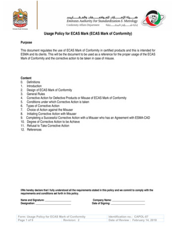
ARINC Standard – Errata Report1. Document TitleARINC Specification 429 Part 1-17: Mark 33 – Digital Information Transfer System (DITS)Published: May 17, 20042. ReferencePage Number: 70Section Number: Att 2 , Table 2Date of Submission:18MAR073. ErrorARINC 429 Part 1, Table 2, BNR Data, (Label 335 reproduced in part):ARINC Specification 429 (May 17, nitsRange(Scale)SigBitsTrack Angle RateTrack Angle RateTrack Angle 15MinTransmitInterval(msec)2101010Track Angle RateDeg/Sec32110.0151020Track Angle RateTrack Angle seResolutionMaxTransPort Delay(msec)3Notes4. Recommended CorrectionARINC 429 Part 1, Table 2, BNR Data (Label 335 reproduced in part). Changes are shaded in yellow.ARINC Specification 429 Part 1-17 10A10BARINC Errata Form11/24/2004ParameterNameUnitsTrack Angle RateTrack Angle RateTrack Angle osSenseDeg/SecDeg/SecDeg/Sec 32 32 STrack Angle RateDeg/Sec 3211CW0.0151020ADIRSTrack Angle RateTrack Angle RateDeg/SecDeg/Sec 32 321111CWCW0.0150.01510102020GLNUGNUResolutionNotes
5. Reason for CorrectionTable 2 from ARINC Specification 429 Part 1 provides baseline definition of Label 335, Track Angle Rate data.“Notes” column is expanded to show the system acronym for each of the sources identified by the “EquipmentID”. Positivr sense is specified as CW (clockwise) to conform to ARINC 705, AHRS, and ARINC 718A,Transponder.6. Submitter (Optional)Robert H. (Bob) Saffell (Rockwell Collins) and Paul Prisaznuk (AEEC staff)Comments should be directed to daniel.martinec@arinc.com.Note: Items 2-5 may be repeated for additional errata. All recommendations will be evaluated by the staff. Anysubstantive changes will require submission to the relevant subcommittee for incorporation into a subsequentSupplement.[To be completed by IA Staff ]Errata Report Identifier: 07-051/ERR-005Review Status:ARINC Errata Form11/24/2004Engineer Assigned: Dan Martinec
2004 byAERONAUTICAL RADIO, INC.2551 Riva RoadAnnapolis, Maryland 21401-7465 USAARINC SPECIFICATION 429 PART 1-17MARK 33 DIGITAL INFORMATION TRANSFER SYSTEM (DITS)PART 1FUNCTIONAL DESCRIPTION, ELECTRICAL INTERFACE,LABEL ASSIGNMENTS AND WORD FORMATSPublished: May 17, 2004Prepared by the Airlines Electronic Engineering CommitteeSpecification 429Specification 429Adopted by the Airlines Electronic Engineering Committee:Adopted by the Industry:July 21, 1977September 15, 1977Summary of Document SupplementsSupplementAdoption DatePublishedSpecification 429-1Specification 429-2Specification 429-3Specification 429-4Specification 429-5Specification 429-6Specification 429-7Specification 429-8Specification 429-9Specification 429-10Specification 429-11Specification 429-12Specification 429-13Specification 429-14Specification 429-15Specification 429-16Specification 429-17April 11, 1978December 6, 1978August 31, 1979June 17, 1980March 12, 1981December 9, 1981November 4, 1982November 4, 1983October 11, 1984November 7, 1985June 15, 1988October 25, 1989October 8, 1991November 4, 1992April 18, 1995November 14, 2000May 5, 2004June 1, 1978March 1, 1979November 1, 1979August 1, 1980April 4, 1981January 22, 1982January 3, 1983December 3, 1984April 30, 1985November 17, 1986July 22, 1988July 1, 1990December 30, 1991January 4, 1993September 1, 1995September 27, 2001May 17, 2004A description of the changes introduced by each supplement is included on goldenrod paper at the end of this document.
FOREWORDAeronautical Radio, Inc., the AEEC, and ARINC StandardsAeronautical Radio, Inc. (ARINC) was incorporated in 1929 by four fledgling airlines in the UnitedStates as a privately-owned company dedicated to serving the communications needs of the air transportindustry. Today, the major U.S. airlines remain the Company’s principal shareholders. Othershareholders include a number of non-U.S. airlines and other aircraft operators.ARINC sponsors aviation industry committees and participates in related industry activities that benefitaviation at large by providing technical leadership and guidance and frequency management. Theseactivities directly support airline goals: promote safety, efficiency, regularity, and cost-effectiveness inaircraft operations.The Airlines Electronic Engineering Committee (AEEC) is an international body of airline technicalprofessionals that leads the development of technical standards for airborne electronic equipmentincluding avionics and in-flight entertainment equipment-used in commercial, military, and businessaviation. The AEEC establishes consensus-based, voluntary form, fit, function, and interface standardsthat are published by ARINC and are known as ARINC Standards. The use of ARINC Standards resultsin substantial benefits to airlines by allowing avionics interchangeability and commonality and reducingavionics cost by promoting competition.There are three classes of ARINC Standards:a) ARINC Characteristics – Define the form, fit, function, and interfaces of avionics and otherairline electronic equipment. ARINC Characteristics indicate to prospective manufacturers ofairline electronic equipment the considered and coordinated opinion of the airline technicalcommunity concerning the requisites of new equipment including standardized physical andelectrical characteristics to foster interchangeability and competition.b) ARINC Specifications – Are principally used to define either the physical packaging ormounting of avionics equipment, data communication standards, or a high-level computerlanguage.c) ARINC Reports – Provide guidelines or general information found by the airlines to be goodpractices, often related to avionics maintenance and support.The release of an ARINC Standard does not obligate any airline or ARINC to purchase equipment sodescribed, nor does it establish or indicate recognition or the existence of an operational requirement forsuch equipment, nor does it constitute endorsement of any manufacturer’s product designed or built tomeet the ARINC Standard.In order to facilitate the continuous product improvement of this ARINC Standard, two items are includedin the back of this volume:a) An Errata Report solicits any corrections to the text or diagrams in this ARINC Standard.b) An ARINC IA Project Initiation/Modification (APIM) form solicits any recommendations foraddition of substantive material to this volume which would be the subject of a newSupplement.ii
ARINC SPECIFICATION 429TABLE OF 4.3INTRODUCTIONPurpose of this DocumentOrganization of ARINC Specification 429Relationship to ARINC Specification 419“Mark 33 Digital Information Transfer System” Basic PhilosophyNumeric Data TransferISO Alphabet No. 5 Data TransferGraphic Data 12.4.1.22.4.22.4.32.4.42.4.5DIGITAL INFORMATION TRANSFER SYSTEM STANDARDSMessage Related ElementsDirection of Information FlowInformation ElementInformation IdentifierSource/Destination IdentifierSign/Status MatrixBCD NumericBNR Numeric Data WordsDiscrete Data WordsData StandardsElectrically Related ElementsTransmission System InterconnectModulationVoltage LevelsTransmitter Voltage LevelsReceiver Voltage LevelsImpedance LevelsTransmitter Output ImpedanceReceiver Input ImpedanceFault ToleranceReceiver External Fault Voltage ToleranceTransmitter External Fault VoltageTransmitter External Fault Load ToleranceFault IsolationReceiver Fault IsolationTransmitter Fault IsolationLogic Related ElementsDigital LanguageNumeric DataDiscretesMaintenance Data (General Purpose)AIM DataFile Data TransferBit-Oriented Protocol DeterminationTransmission OrderData Bit Encoding LogicError Detection/CorrectionTiming Related ElementsBit RateHigh Speed OperationLow Speed OperationInformation RatesClocking MethodWord SynchronizationTiming ARK 33 DITS APPLICATIONS NOTESRadio Systems ManagementWord Format and Digital LanguageUpdate RateSign/Status MatrixFrequency Ranges and Switching FunctionsADFDME1111111111111111iii
ARINC SPECIFICATION 429TABLE OF 63.1.4.73.2HF CommunicationsILSVOR/ILSVHF CommunicationsATC TransponderAIM Information 1011Label CodesEquipment CodesData StandardsVoltage LevelsInput/Output Circuit StandardsInternational Standards Organization Code #5General Word Formats and Encoding ExamplesData Bit Encoding LogicOutput Signal Timing TolerancesGeneral Aviation Labels and Data StandardsGeneral Aviation Word ExamplesGeneral Aviation Equipment IdentifiersManufacturer Specific Status WordSystem Address SABCDEXLaboratory Verification of ARINC 429 DITS Electrical CharacteristicsAn Approach to a Hybrid Broadcast-Command/Response Data Bus ArchitectureDigital Systems Guidance (Part 1)Digital Systems Guidance (Part 2)Guidelines for Label AssignmentsChronology & Bibliography132165170177182184ARINC Standard – Errata ReportARINC IA Project Initiation/Modification (APIM)iv
ARINC SPECIFICATION 429, PART 1 - Page 11.0 INTRODUCTION1.1 Purpose of this Document1.4 “Mark 33 Digital Information Transfer System”- Basic PhilosophyThis document defines the air transport industry’s standardsfor the transfer of digital data between avionics systemselements. Adherence to these standards is desired for allinter-systems communications in which the system linereplaceable units are defined as unit interchangeable in therelevant ARINC characteristics. Their use for intra-systemcommunications in systems in which the line replaceableunits are defined in the ARINC characteristics as systeminterchangeable is not essential, although it may beconvenient.This “Mark 33 Digital Information Transfer System(DITS)” specification describes a system in which anavionics system element having information to transmitdoes so from a designated output port over a single twistedand shielded pair of wires to all other system elementshaving need of that information. Bi-directional data flow ona given twisted and shielded pair of wires is not permitted.1.2 Organization of ARINC Specification 429ARINC Specification 429 was originally published in asingle volume through version 14 (429-14). The size of thedocument and the need for improved organization dictatedthe division of the document into three parts. Those threeparts include:Part 1 Functional Description, Electrical Interface, LabelAssignments and Word FormatsPart 2 Discrete Word Data FormatsPart 3 File Data Transfer Techniquesc-15 Part 1 provides the basic description of the functions andthe supporting physical and electrical interfaces for the datatransfer system. Data word formats, standard label andaddress assignments, and application examples are defined.Part 2 lists discrete word bit assignments in label order. Part3 describes protocols and message definitions for datatransferred in large blocks and/or file format.Forconvenience of the user, the section and attachmentnumbering has been retained for the material moved fromthe original Specification to Part 3.Updates to each part of future releases of ARINC 429 willbe independent of the other parts to accommodate timelyrevisions as industry needs dictate. The dash numbers foreach Part will NOT be synchronized with the other Parts astime passes. Users of ARINC Specification 429 shouldensure that the latest version of each Part is used whendesigning or procuring equipment.1.3 Relationship to ARINC Specification 419ARINC Specification 419, “Digital Data SystemCompendium”, is a catalog of the elements of the severaldigital data transmission systems that have foundapplication during the “emergent” period of digital avionicstechnology. The maturing of this technology, now evidentin the scope of its planned use on aircraft of the 1980s andbeyond, has shown the need for a generally applicabledigital information transfer system having capabilities notprovided by any combination of the elements presentlydefined in Specification 419. In defining such a system, thisdocument draws on the experience gained in the preparationof Specification 419 but is otherwise separate and distinctfrom it. Addition of the element specifications of thesystem defined herein to the Specification 419 catalog is notanticipated.1.4.1 Numeric Data TransferThe Mark 33 DITS numeric data transmissioncharacteristics have been developed from those ofsuccessful predecessor air transport industry digitalinformation transfer systems.Data for transmission,encoded in either twos complement fractional binarynotation or binary coded decimal notation, is supplied fromsource systems at rates sufficiently high to ensure smallincremental value changes between updates. Transmissionis made “open loop”, i.e., sinks are not required to informsources that information has been received. A parity bit istransmitted as part of each data word to permit simple errorchecks to be performed by the sinks. These, together withdata reasonableness checks which may also be performedby the sinks, may be used to prevent the display or otherutilization of a erroneous or suspect word. The inherentlyhigh integrity of the twisted and shielded wire transmissionmedium ensures that such drop-outs are few. The low ratesof change of the data ensure that when one does occur, it isof no consequence.1.4.2 ISO Alphabet No. 5 Data TransferIn addition to the transfer of BNR and BCD numeric data asjust described, the Mark 33 DITS handles alpha andnumeric data encoded per ISO Alphabet No. 5. The same“broadcast” transmission philosophy is used, although the c-1“housekeeping” aspects of system operation differ in orderto accommodate particular needs associated with this typeof data. These differences will be addressed individually inthis document as they arise.1.4.3 Graphic Data TransferA third type of data which may eventually be handled by theMark 33 DITS is graphic data, i.e., the lines, circles,randomly positioned alpha/numeric text and other symbolsused on CRT map and similar displays. The techniqueemployed for this purpose can be basically similar to that c-1used for ISO Alphabet No. 5 alpha/numeric data transfer.However, because a need for graphic data handlingcapability has not yet emerged, the air transport industry hasdecided not to be specific concerning this technique for themoment. When the need for graphic data handling isestablished, appropriate specification material will bedeveloped.
ARINC SPECIFICATION 429, PART 1 - Page 22.0 DIGITAL INFORMATION TRANSFER SYSTEM STANDARDScharacters towards the MSB by two bit positions. It ispossible, however, that future latitude and longitudedisplays will not be the simple, dedicated read-out typefor which BCD data is intended. More likely is the use c-1of some form of multiple-message display, such as aCRT, which will be backed by its own data processorand prefer inputs of BNR data. If this proves to be thecase, these special provisions for BCD-encoding willnot be required.2.1 Message Related ElementsThis section describes the digital data transfer systemelements considered to be principally related to the messageitself or the manner in which it is handled.2.1.1 Direction of Information FlowThe information output of an avionics system elementshould be transmitted from a designated port (or ports) towhich the receiving ports of other system elements in needof that information are connected. In no case doesinformation flow into a port designated for transmission.COMMENTARYA separate data bus (twisted and shielded pair of wiresper Section 2.2.1) for each direction is used when datais required to flow both ways between two avionicssystems elements.2.1.2 Information ElementThe basic information element is a digital word containing32 bits. There are five application groups for such words,BNR data, BCD data, Discrete data, Maintenance data(general) and Acknowledgement, ISO Alphabet Number 5and Maintenance (ISO Alphabet Number 5) data (AIM).Word formats for these different applications are depictedc-2 in Attachment 6 while the relevant data handling rules areset forth in Section 2.3.1. When less than the full data fieldis needed to accommodate the information conveyed in aword in the desired manner, the unused bit positions shouldbe filled with binary zeros or, in the case of BNR/BCDnumeric data, valid data bits. If valid data bits are used, theresolution possible for the information may exceed thatcalled for in this Specification. The Commentary followingSection 2.1.6 of this document refers.COMMENTARYc-1c-1To permit the use of identical error-checking hardwareelements in the handling of BNR and BCD numericdata words, the format for the Mark 33 DITS BCDword differs from that used formerly for this type ofdata. Bit Number 32 is assigned to parity, BitNumbers 31 and 30 to the sign/status matrix, BitNumber 29 is the most significant bit of the data field,and the maximum decimal value of the mostsignificant character is 7. Previously, the BCD wordcontained no parity bit, the sign/status matrix occupiedBit Numbers 32 and 31, Bit Number 30 was the mostsignificant data bit and the maximum decimal value ofthe most significant character was 3. This format madethe word 8-bit byte oriented with respect to the data.This characteristic is not retained in the Mark 33system.Also, latitude and longitude can only be encoded in theMark 33 DITS word with the formerly specifiedresolution of 0.1 minute of arc if Bit Numbers 9 and 10are used for data rather than the SDI function describedin Section 2.1.4 of this document, and the word isstructured differently from the standard shown inAttachment 6.Restructuring the word involveslimiting the maximum value of the most significantcharacter to 1 and moving the remaining BCD2.1.3 Information IdentifierThe type of information contained in a word is identified by c-2a six-character label. The first three characters are octalcharacters coded in binary in the first eight bits of the word.c-4The eight bits will:a.b.identify the information contained within BNR andBCD numeric data words (e.g., DME distance, staticair temperature, etc.) andc-2identify the word application for Discrete, Maintenanceand AIM data.The last three characters of the six-character label arehexadecimal characters used to provide for identification ofARINC 429 bus sources. Each triplet of hexadecimalcharacters identifies a “black box” with one or more DITS c-12ports. Each three character code (and black box) may haveup to 255 eight bit labels assigned to it. The code is usedadministratively to retain distinction between unlikeparameters having like labels assignments.COMMENTARYSome users have expressed a desire to have means foridentifying label sets and buses associated with aparticular equipment ID code. Octal label 377 hasbeen assigned for this purpose. (The code appears inthe 3 LSDs of the BCD Word format).Thetransmission of the equipment identifier word on a bus c-4will permit receivers attached to the bus to recognizethe source of the DITS information. Since thetransmission of the equipment identifier word isoptional, receivers should not depend on that word forcorrect operation.Label code assignments are set forth in Attachment 1-1 c-2to this document.Special Note:In some ARINC 429 DITS applications, a bus will bededicated to delivering a single information element from asource to one or more identical sink devices. In suchcircumstances, the sink device designer might be tempted toassume that decoding the word label is not necessary.Experience has shown, however, that system developments c-1frequently occur that result in the need for additionalinformation elements to appear on the bus. If a sink devicedesigned for service prior to such a development cannotdecode the original word label, it cannot differentiatebetween this word and the new data in the new situation.The message for sink designers should therefore be quiteclear - provide label decoding from the outset, no matterhow strong the temptation to omit it might be.
ARINC SPECIFICATION 429, PART 1 - Page 32.0 DIGITAL INFORMATION TRANSFER SYSTEM STANDARDSCOMMENTARYAdherence to the label code assignments ofAttachment 1-1 is essential in inter-systemcommunications and in intra-system communicationswhere the system elements are defined as “unitinterchangeable” per ARINC Report 403.Theassignment of label codes for all such communicationsmust be coordinated with the air transport industry ifchaos is to be avoided. A manufacturer who finds thatAttachment 1-1 does not specify the label he needs forsuch system application must not simply choose onefrom those unassigned and drive on. The user shouldcontact AEEC Staff for assistance. A web page on theARINC Website (ARINC.com) has been developed toassist you in contacting the AEEC Staff.code “00” is available as an “installation Number 4”identifier. When the SDI function is not used, binary zerosor valid data should be transmitted in Bit Numbers 9 and10.COMMENTARYThis document does not address the practical questionof how the SDI bits will be set in those multiinstallation systems in which the source/destinationfunction is desired. One way would be to use programpins on the individual installation black boxes which c-1would be wired to set up the appropriate code. TheARINC Characteristics devoted to the individualsystems will define the method actually to be used.2.1.5 Sign/Status Matrix2.1.4 Source/Destination IdentifierBit Numbers 9 and 10 of numeric data words should bereserved for a data source/destination identificationfunction. They are not available for this function inalpha/numeric (ISO Alphabet Number 5) data words (seeSection 2.3.1.3 of this document) or when the resolutionneeded for numeric (BNR/BCD) data necessitates their useof valid data. The source/destination identifier functionc-1 may find application when specific words need to bedirected to a specific system of a multi-system installationor when the source system of a multi-system installationneeds to be recognizable from the word content. When it isused, a source equipment should encode its aircraftinstallation number in Bit Numbers 9 and 10 as shown inthe table below. A sink equipment should recognize wordscontaining its own installation number code and wordscontaining code “00,” the “all-call” code.COMMENTARYc-8Equipment will fall into the categories of source only,sink only, or both source and sink. Use of the SDI bitsby equipment functioning only as a source or only as asink is described above. Both the source and sink textsabove are applicable to equipment functioning as botha source and a sink. Such equipment should recognizethe SDI bits on the inputs and should also encode theSDI bits, as applicable, on the outputs. DME, VOR,ILS and other sensors, are examples of source and sinkequipment generally considered to be only sourceequipment. These are actually sinks for their owncontrol panels. Many other types of equipment are alsomisconstrued as source only or sink only. A simplerule of thumb is: if a unit has a 429 input port and a429 output port, it is a source and sink! With theincrease of equipment consolidation, e.g., centralizedcontrol panels, the correct use of the SDI bits cannot beoverstressed.Bit Number10900110101Installation NumberSee Note Below123Note: In certain specialized applications of the SDIfunction the all-call capability may be forfeited so thatThis section describes the coding of the Sign/Status Matrix(SSM) field. In all cases the SSM field uses Bits 30 and 31.For BNR data words, the SSM field also includes Bit 29.The SSM field may be used to report hardware equipmentcondition (fault/normal), operational mode (functional test),or validity of data word content (verified/no computeddata).The following definitions apply in this Specification:Invalid Data - is defined as any data generated by a sourcesystem whose fundamental characteristic is the inability toconvey reliable information for the proper performance of auser system. There are two categories of invalid data,namely, “No Computed Data” and “Failure Warning.”No Computed Data - is a particular case of data invaliditywhere the source system is unable to compute reliable datafor reasons other than system failure. This inability tocompute reliable data is caused exclusively by a definite setof events or conditions whose boundaries are uniquelydefined in the system characteristic.Failure Warning - is a particular case of data invaliditywhere the system monitors have detected one or more c-12failures. These failures are uniquely characterized byboundaries defined in the system characteristic.The system indicators should always be flagged during a“Failure Warning” condition.When a “No Computed Data” condition exists, the sourcesystem should annunciate its outputs to be invalid by settingthe sign/status matrix of the affected words to the “NoComputed Data” code, as defined in the subsections whichfollow. The system indicators may or may not be flagged,depending on system requirements.While the unit is in the functional test mode, all output datawords generated within the unit (i.e., pass through words areexcluded) should be coded for “Functional Test.” Passthrough data words are those words received by the unit andretransmitted without alteration.When the SSM code is used to transmit status and morethan one reportable condition exists, the condition with thehighest priority should be encoded in Bit Numbers 30 and31. The order of condition priorities to be used is shown inthe table below.
ARINC SPECIFICATION 429, PART 1 - Page 42.0 DIGITAL INFORMATION TRANSFER SYSTEM STANDARDS2.1.5 Sign/Status Matrix (cont’d)Failure WarningNo Computed DataFunctional TestNormal OperationPriority 1Priority 2Priority 3Priority 4Each data word type has its own unique utilization of theSSM field. These various formats are described in thefollowing subsections.2.1.5.1 BCD NumericWhen a failure is detected within a system which wouldcause one or more of the words normally output by thatsystem to be unreliable, the system should stop transmittingthe affected word or words on the data bus.c-12BCD NUMERIC SIGN/STATUS MATRIXBit Number313000100111MeaningPlus, North, East, Right, To, AboveNo Computed DataFunctional TestMinus, South, West, Left, From, Below2.1.5.2 BNR Numeric Data WordsThe status of the transmitter hardware should be encoded inthe Status Matrix field (Bit Numbers 30 and 31) of BNRNumeric Data words as shown in the table below.Some avionic systems are capable of detecting a faultcondition which results in less than normal accuracy. Inthese systems, when a fault of this nature (for instance,partial sensor loss) which results in degraded accuracy isdetected, each unreliable BCD digit should be encoded“1111” when transmitted on the data bus. For equipmentshaving a display, the “1111” code should, when received,be recognized as representing an inaccurate digit and a“dash” or equivalent symbol should be displayed in place ofthe inaccurate digit. Parameters for which such a degradedmode of operation is possible are identified in the Notecolumn of the tables in Attachment 2.A source system should annunciate any detected failure thatcauses one or more of the words normally output by thatsystem to be unreliable by setting Bit Numbers 30 and 31 inthe affected word(s) to the “Failure Warning” code definedin the table below. Words containing this code shouldcontinue to be supplied to the data bus during the failurecondition.The sign (plus/minus, north/south, etc.) of BCD NumericData should be encoded in bit numbers 30 and 31 of theword as shown in the table below. Bit Numbers 30 and 31of BCD Numeric Data words should be “zero” where nosign is needed.When it appears as a system output, the “Functional Test”code should be interpreted as advice that the data in theword results from the execution of a functional test. Afunctional test should produce indications of 1/8 of positivefull-scale values unless indicated otherwise in an ARINCequipment characteristic.The “No Computed Data” code should be annunciated inthe affected BCD Numeric Data word(s) when a sourcesystem is unable to compute reliable data for reasons otherthan system failure.When the “Functional Test” code appears in Bits 30 and 31of an instruction input data word, it should be interpreted asa command to perform a functional test.The “No Computed Data” code should be annunciated inthe affected BNR Numeric Data word(s) when a sourcesystem is unable to compute reliable data for reasons otherthan system failure.If, during the executio
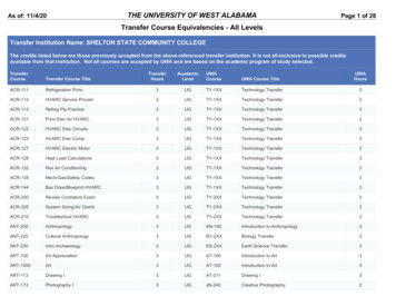
ARINC 429 Part 1, Table 2, BNR Data (Label 335 reproduced in part). Changes are shaded in yellow. ARINC Specification 429 Part 1-17 REVISED Label Eqpt ID (HEX) Parameter Name Units . A Laboratory Verification of ARINC 429 DITS Electrical Characteristics 132 B An Approach to a Hybrid Broadcast-Command/Response Data Bus Architecture 165