Transcription
ARINC 781-200 SDU and SCMSystem Description, Installation, and Maintenance ManualMN-0000243, Revision 1.0This document provides procedures for the equipment listed below.ModelARINC 781-200 Satellite Data UnitARINC 781-200 SDU Configuration Module—SingleSBBARINC 781-200 SDU Configuration Module—DualSBB23-15-30Part Number1530-A-11001530-A-1300-011530-A-1300-02TITLE PAGE T-1DATE TBD
PROPRIETARY STATEMENTThis document contains information that is proprietary and confidential to either or both of EMS TechnologiesCanada, Ltd., or EMS Aviation Inc. (collectively "EMS Aviation") and is supplied on the express condition thatit is not to be used for any purpose other than the purpose for which it was issued, nor is it to be copied orcommunicated in whole or in part, to any third party other than the recipient organization, without the priorwritten permission of EMS Aviation. 2012 EMS Technologies Canada, Ltd., EMS Aviation Inc.ARINC 781-200 SDU and SCM System Description, Installation, and Maintenance ManualDocument Number: MN-0000243, Revision 1.0Revision TableRevisionECRDescriptionWindows is a registered trademark of Microsoft Corporation in the United States and other countries. Otherproduct, brand, service, and company names herein are the trademarks of their respective owners.Our products are under continuous research and development. Any information may therefore be changedwithout prior notice. EMS Aviation reserves the right to make improvements or changes in the product describedin this manual at any time without notice. While reasonable efforts have been made in the preparation of thisdocument to assure its accuracy, EMS Aviation assumes no liability resulting from any errors or omissions inthis document, or from the use of the information contained herein.Printed in Canada.EMS Aviation400 Maple Grove Road, Ottawa, Ontario, K2V 1B8, CANADAEMS Aviation Reception:(613) 591-9064EMS Aviation Product Support:(888) 300-7415 (calls are routed to an on-call Product Support specialistafter regular business hours) 44 1684 290 020 (UK)(613) 591-3086 (outside North America)EMS Aviation E-mail Help:support@emsaviation.comEMS Aviation Web site:www.emsaviation.comEMS Aviation Sales and Marketing:800-600-975923-15-30TITLE PAGE T-2DATE TBD
CUSTOMER RESPONSE FORMTo help us improve the quality of our product documentation, EMS Aviation would appreciate yourcomments and suggestions on this publication. Please complete the following customer survey andsend to EMS Aviation at:EMS Aviation 400 Maple Grove Road Ottawa, ON K2C 0P9E-mail: techdocs@emsaviation.comPublication information:Publication number:MN-0000243Publication title:ARINC 781-200 SDU and SCM System Description, Installation, andMaintenance ManualLatest issue date:DATE TBDDocument revision:1.0Customer information:Name:Company:Tel:Fax:Email:Comments and suggestions:Date:Comments:23-15-30CR-1DATE TBD
Blank Page23-15-30CR-2DATE TBD
SYSTEM DESCRIPTION, INSTALLATION, AND MAINTENANCE MANUALARINC 781-200 SDU and SCMRECORD OF REVISIONSWhen revisions are received, insert revised pages, record the date, and dby edInsertedby (initial)RR-1DATE TBD
SYSTEM DESCRIPTION, INSTALLATION, AND MAINTENANCE MANUALARINC 781-200 SDU and SCMBlank Page23-15-30RR-2DATE TBD
SYSTEM DESCRIPTION, INSTALLATION, AND MAINTENANCE MANUALARINC 781-200 SDU and SCMSERVICE BULLETIN LISTService BulletinNumberSubject23-15-30Manual Rev. Manual Rev.NumberDateSBL-1DATE TBD
SYSTEM DESCRIPTION, INSTALLATION, AND MAINTENANCE MANUALARINC 781-200 SDU and SCMBlank Page23-15-30SBL-2DATE TBD
SYSTEM DESCRIPTION, INSTALLATION, AND MAINTENANCE MANUALARINC 781-200 SDU and SCMLIST OF EFFECTIVE PAGES* An asterisk indicates pages changed, added, or deleted by the current revision.F indicates a right foldout page with a blank back.SectionPage23-15-30DateLEP-1DATE TBD
SYSTEM DESCRIPTION, INSTALLATION, AND MAINTENANCE MANUALARINC 781-200 SDU and SCMBlank Page23-15-30LEP-2DATE TBD
SYSTEM DESCRIPTION, INSTALLATION, AND MAINTENANCE MANUALARINC 781-200 SDU and SCMTABLE OF CONTENTSINTRODUCTION1. Illustration of Equipment . INTRO-12. Acronyms and Abbreviations . INTRO-23. Safety Advisories . INTRO-4SYSTEM DESCRIPTION1. Inmarsat System Overview. 1-12. Equipment Overview . 1-2A. SDU . 1-3B. SCM . 1-33. Equipment Specifications . 1-44. System Interfaces. 1-6A. SDU . 1-7B. SCM . 1-85. User Interfaces . 1-8A. MCDU . 1-8B. 4-Wire Audio . 1-8C. Ethernet . 1-8D. POTS . 1-9E. CEPT-E1 . 1-9F. ISDN . 1-9G. Maintenance Port . 1-9H. LEDs . 1-9I. Self-Test Button . 1-96. Software Description . 1-10SYSTEM OPERATION1. Registering and Activating Terminals . 2-1A. Obtaining ICAO Addresses . 2-1B. Choosing Service Providers . 2-1C. Registering Terminals . 2-123-15-30TC-1DATE TBD
SYSTEM DESCRIPTION, INSTALLATION, AND MAINTENANCE MANUALARINC 781-200 SDU and SCM2. Using the A781-200 System . 2-2A. Operating the MCDU . 2-2(1) Screen. 2-2(2) Keyboard. 2-3(3) Special Symbols. 2-4(4) Navigating the MCDU . 2-4B. Logging On and Off . 2-5(1) Logging On Automatically . 2-6(2) Logging On Manually . 2-6(3) Logging Off Classic Aero Services. 2-7(4) Viewing Log Status. 2-7C. Enabling and Disabling the Cabin Telecommunications Unit (CTU) . 2-8(1) Disabling CTU calls. 2-8(2) Enabling CTU calls. 2-9D. Accepting and Making Calls in the Cockpit . 2-9(1) Making Cockpit Calls. 2-9(2) Call Priority and call Pre-emption. 2-13(3) Saving Telephone Numbers in the Telephone Directory . 2-13E. Viewing BITE Information . 2-153. Channel Status and System Configuration . 2-16A. SBB Status . 2-16B. Swift 64 . 2-18C. Channel Information and Bit Errors . 2-20D. System Part Numbers . 2-214. Maintenance Mode . 2-23A. Accessing Maintenance Mode . 2-24B. Viewing BITE Information . 2-26C. Starting the Intermod Test . 2-26D. Viewing Configuration . 2-26E. Viewing SATCOM Parameters . 2-26F. Viewing SATCOM Options . 2-27G. Configuring Audio Options . 2-28INSTALLATION1. Advisories . 3-12. Pre-Installation Inspection . 3-1A. Unpacking and Inspecting Equipment . 3-123-15-30TC-2DATE TBD
SYSTEM DESCRIPTION, INSTALLATION, AND MAINTENANCE MANUALARINC 781-200 SDU and SCMB. Cabling Notes . 3-13. Installation Procedure. 3-24. Connection Details. 3-2A. SDU . 3-2B. SCM . 3-75. Owners Requirements Table (ORT) . 3-8A. ORT Overview . 3-86. Passive Intermodulation (PIM) Test. 3-8A. Overview . 3-8B. PIM Requirements . 3-8C. PIM Test . 3-9D. PIM Test Results . 3-9(1) PIM Test Overall Status. 3-9(2) Directional PIM Test Results . 3-107. Installation and Engineering Drawings . 3-10A. Outline and Installation Drawings . 3-10B. System Interconnect Drawings . 3-10TEST AND FAULT ISOLATION1. Operational and Diagnostic Testing . 4-1A. General . 4-1B. Test and Fault Isolation Equipment Requirements . 4-1C. SDU Maintenance Port Utility (MPU) . 4-2(1) Connecting to the MPU . 4-2(2) Using the SDU MPU . 4-3(3) Menu Item Descriptions . 4-4D. Operational and Diagnostic Test Procedures . 4-5(1) Test Setup Procedure. 4-6(2) Post Test . 4-6(3) Installation and Operational Verification Tests . 4-62. Troubleshooting and Fault Isolation . 4-7A. Subsystem Health . 4-7B. SATCOM System Bus . 4-8C. Thermal Status . 4-10D. SCM Health . 4-11E. Subsystem Bus Status . 4-1323-15-30TC-3DATE TBD
SYSTEM DESCRIPTION, INSTALLATION, AND MAINTENANCE MANUALARINC 781-200 SDU and SCMF. RF Path Status . 4-13G. USIM and Data Bus Status . 4-14H. ORT . 4-15(1) Checking the ORT. 4-15I. Contact Product Support . 4-153. Adjustment/Alignment Procedures . 4-164. Modification History. 4-16MAINTENANCE AND REPAIR1. Maintenance. 5-12. Repair . 5-13. Instructions for Continued Airworthiness . 5-1A. Airworthiness Limitations . 5-2B. Electrical and Mechanical Inspection and Check . 5-2C. Instructions for Continued Airworthiness . 5-24. Visual Inspection and Check. 5-3APPENDIX A: RETURN MATERIAL AUTHORIZATION . A-11. Warranty Returns . A-12. Non-Warranty Returns . A-13. Repackaging Requirements . A-14. RMA Procedure . A-123-15-30TC-4DATE TBD
SYSTEM DESCRIPTION, INSTALLATION, AND MAINTENANCE MANUALARINC 781-200 SDU and SCMLIST OF FIGURESFigure INTRO-1 Satellite Data Unit .INTRO-1Figure INTRO-2 SDU Configuration Module .INTRO-2Figure 1-1 Simplified Aeronautical Satellite Communications System . 1-2Figure 1-2 A781-200 Avionics System . 1-3Figure 1-3 A781-200 Avionics System Block Diagram . 1-7Figure 2-1 MCDU Screen . 2-3Figure 2-2 A781-200 MCDU Menu Structure . 2-5Figure 2-3 SBB menu . 2-17Figure 2-4 Swift 64 Menu. 2-19Figure 2-5 SATCOM LOG 2 menu . 2-20Figure 2-6 SATCOM CONFIG 1 menu . 2-21Figure 2-7 SATCOM CONFIG 2 menu . 2-22Figure 2-8 SATCOM CONFIG 3 menu . 2-23Figure 2-9 Maintenance Mode MDCU Menu Structure . 2-24Figure 2-10 SATCOM PARMS . 2-27Figure 2-11 SATCOM OPTIONS . 2-28Figure 2-12 CONFIG AUDIO 1/2 . 2-29Figure 2-13 CONFIG AUDIO 2/2 . 2-30Figure 3-1 Top Plug Pin Deviations . 3-5Figure 3-2 Mid Plug Pin Deviations . 3-6Figure 3-3 ARINC 781-200 SDU Outline and Installation Drawing, 1530-E-1100 Rev B00 (Sheet 1of 2) . 3-11Figure 3-4 ARINC 781-200 SDU Outline and Installation Drawing, 1530-E-1100 Rev B00 (Sheet 2of 2) . 3-13Figure 3-5 ARINC 781-200 SCM Outline and Installation Drawing, 1530-E-1300 Rev C00 (Sheet 1of 2) . 3-15Figure 3-6 ARINC 781-200 SCM Outline and Installation Drawing, 1530-E-1300 Rev C00 (Sheet 2of 2) . 3-17Figure 3-7 ARINC 781-200 System Interconnect Drawing, 1530-B-1001 Rev C00 (Sheet 1 of 3).3-19Figure 3-8 ARINC 781-200 System Interconnect Drawing, 1530-B-1001 Rev C00 (Sheet 2 of 3).3-21Figure 3-9 ARINC 781-200 System Interconnect Drawing, 1530-B-1001 Rev C00 (Sheet 3 of 3).3-23Figure 4-1 Maintenance Cable . 4-223-15-30TC-5DATE TBD
SYSTEM DESCRIPTION, INSTALLATION, AND MAINTENANCE MANUALARINC 781-200 SDU and SCMFigure 4-2 SATCOM Subsystem Health Menu . 4-8Figure 4-3 SATCOM System Bus Menu . 4-9Figure 4-4 SATCOM Overtemp Menu . 4-11Figure 4-5 SATCOM SCM Menu . 4-12Figure 4-6 SATCOM Subsystem Bus Menu . 4-13Figure 4-7 SATCOM RF Path Menu . 4-14Figure 4-8 SATCOM USIM/DATA Menu . 4-1523-15-30TC-6DATE TBD
SYSTEM DESCRIPTION, INSTALLATION, AND MAINTENANCE MANUALARINC 781-200 SDU and SCMLIST OF TABLESTable 1-1 SDU Physical Characteristics and Specifications. 1-4Table 1-2 SCM Physical Characteristics and Specifications . 1-5Table 1-3 ARINC 781-200 SDU and SCM RTCA/DO-160E Environmental Characteristics . 1-6Table 1-4 SDU System Interfaces . 1-8Table 1-5 SDU LED Status . 1-9Table 2-1 A781-200 System Log Status . 2-7Table 2-2 SBB Menu . 2-17Table 2-3 Swift 64 Menu . 2-19Table 2-4 SATCOM LOG 2 Menu. 2-20Table 2-5 SATCOM CONFIG 1 Menu . 2-21Table 2-6 SATCOM CONFIG 2 Menu . 2-22Table 2-7 SATCOM CONFIG 3 Menu . 2-23Table 2-8 SATCOM PARMS Menu . 2-27Table 2-9 SATCOM OPTIONS Menu . 2-28Table 2-10 SATCOM CONFIG AUDIO 1 Menu . 2-29Table 2-11 SATCOM CONFIG AUDIO 2 Menu . 2-30Table 3-1 SDU Rear Connector Pin Deviations. 3-2Table 3-2 SDU Front Connector DSUB and RJ45 Pin Assignment. 3-7Table 3-3 SCM D-Type Connector Pin Assignment . 3-7Table 4-1 List of Required Test Equipment . 4-2Table 4-2 Maintenance Port Connection Settings . 4-3Table 4-3 Menu 1 Item Descriptions . 4-4Table 4-4 Menu 2 Item Descriptions . 4-4Table 4-5 Menu 3 Item Descriptions . 4-5Table 4-6 Test Setup Procedure. 4-6Table 4-7 Post Test Procedure . 4-6Table 4-8 Power-On Test Procedure . 4-7Table 4-9 SATCOM Subsystem Health Menu . 4-8Table 4-10 Bus Status Indicators. 4-9Table 4-11 SATCOM OVERTEMP Menu . 4-11Table 4-12 SATCOM SCM Menu . 4-12Table 4-13 SATCOM SUBSY BUS Menu. 4-13Table 4-14 SATCOM RF PATH Menu . 4-1423-15-30TC-7DATE TBD
SYSTEM DESCRIPTION, INSTALLATION, AND MAINTENANCE MANUALARINC 781-200 SDU and SCMTable 4-15 SATCOM USIM/DATA Menu. 4-1523-15-30TC-8DATE TBD
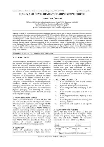
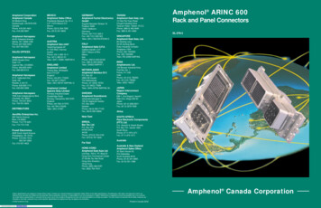
SYSTEM DESCRIPTION, INSTALLATION, AND MAINTENANCE MANUALARINC 781-200 SDU and SCMINTRODUCTIONThis manual provides the specifications, principles of operation, and information necessary to installthe ARINC 781-200 Avionics SATCOM System, including the Satellite Data Unit (SDU) and SDUConfiguration Module (SCM).This document is divided into the following sections: System Description System Operation Installation Test and Fault Isolation Maintenance and RepairNOTE: An Illustrated Parts List is not included with this manual.Only qualified avionics personnel who are knowledgeable in the technical and safety issues relatedto the installation of aircraft communications equipment should perform the installation proceduresprovided in this manual.This manual includes general installation guidelines only; it is not intended to provide specificprocedures for every type of installation.If necessary, the information in this manual will be revised. Before attempting the installationprocedures presented in this manual, verify that you have a complete and up-to-date release of thisdocument.1. Illustration of EquipmentFigure INTRO-1 shows the SDU.Figure INTRO-1 Satellite Data Unit23-15-30INTRO-1DATE TBD
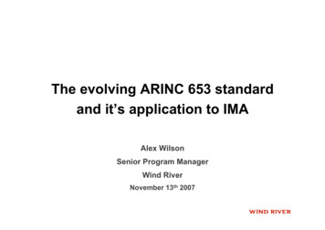
SYSTEM DESCRIPTION, INSTALLATION, AND MAINTENANCE MANUALARINC 781-200 SDU and SCMFigure INTRO-2 shows the SCM.Figure INTRO-2 SDU Configuration Module2. Acronyms and AbbreviationsAESAircraft Earth StationAMSSAeronautical Mobile Satellite ServicesAOREAtlantic Ocean Region-EastAORWAtlantic Ocean lt-In-Test EquipmentBSUBeam Steering UnitCEPTComite Europeen des Postes et TelecommunicationsCTUCabin Telecommunications UnitDLNADiplexer/Low-Noise AmplifierDITSDigital Information Transfer Sys
ARINC 781-200 SDU and SCM System Description, Installation, and Maintenance Manual MN-0000243, Revision 1.0 This document provides procedures for the equipment listed below. Model Part Number ARINC 781-200 Satellite Data Unit 1530-A-1100 ARINC 781-200 SDU Configuration Module—Single SBB 1530-A-1300-01 ARINC 781-200 SDU Configuration Module .