Transcription
CHAPTER 5Principles of Laser Microdissection andCatapulting of Histologic Specimensand Live CellsAlfred Vogel,* Verena HorneVer,* Kathrin Lorenz,*Norbert Linz,* Gereon Hüttmann,* and Andreas Gebert†*Institute of Biomedical Optics, University of LübeckPeter-Monnik Weg 4, D-23562 Lübeck, Germany†Institute of Anatomy, University of LübeckRatzeburger Allee 160, D-23538 Lübeck, GermanyI. IntroductionII. Features of the Microbeam System and Materials UsedIII. Dissection and Catapulting of Histologic SpecimensA. Mechanism of DissectionB. Catapulting with Focused and Defocused Laser PulsesC. Possible Side EVects and Their MinimizationIV. Dissection and Catapulting of Live CellsA. Dissection in a Liquid EnvironmentB. Catapulting of Live-Cell PopulationsC. Possible Side EVects and Their MinimizationV. Conclusions and OutlookA. Potential Improvements for DissectionB. Potential Improvements for CatapultingReferencesRapid contact- and contamination-free procurement of specific samples of histologic material for proteomic and genomic analysis as well as separation andtransport of living cells can be achieved by laser microdissection (LMD) of thesample of interest followed by a laser-induced forward transport process [laserpressure ‘‘catapulting,’’ (LPC)] of the dissected material.METHODS IN CELL BIOLOGY, VOL. 82Copyright 2007, Elsevier Inc. All rights reserved.1530091-679X/07 35.00DOI: 10.1016/S0091-679X(06)82005-4
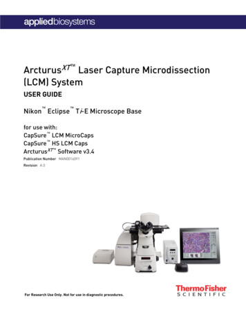
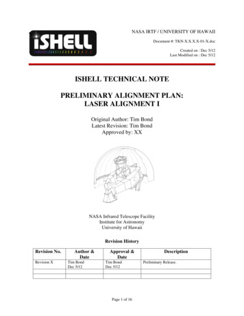
Alfred Vogel et al.154We investigated the dynamics of LMD and LPC with focused and defocusedlaser pulses by means of time-resolved photography. The working mechanism ofmicrodissection was found to be plasma-mediated ablation. Catapulting is drivenby plasma formation, when tightly focused pulses are used, and by ablation atthe bottom of the sample for moderate and strong defocusing. Driving pressuresof several hundred megapascals accelerate the specimen to initial velocities of100–300 m/s before it is rapidly slowed down by air friction. With strong defocusing,driving pressure and initial flight velocity decrease considerably.On the basis of a characterization of the thermal and optical properties of thehistologic specimens and supporting materials used, we calculated the temporalevolution of the heat distribution in the sample. After laser microdissection andlaser pressure catapulting (LMPC), the samples were inspected by scanning electron microscopy. Catapulting with tightly focused or strongly defocused pulsesresults in very little collateral damage, while slight defocusing involves significantheat and UV exposure of up to about 10% of the specimen volume, especially ifsamples are catapulted directly from a glass slide.Time-resolved photography of live-cell catapulting revealed that in defocusedcatapulting strong shear forces originate from the flow of the thin layer of culturemedium covering the cells. By contrast, pulses focused at the periphery of thespecimen cause a fast rotational movement that makes the specimen wind its wayout of the culture medium, thereby undergoing much less shear stresses. Therefore, the recultivation rate of catapulted cells was much higher when focusedpulses were used.I. IntroductionProcurement of specific samples of histologic material for proteomic and genomic analysis has become important with the increasing refinement of analytictechniques. Moreover, separation and transport of living cells is of interest forstem cell research, organ culture, or tissue engineering. Mechanical separationtechniques are tedious, time consuming, and bear the risk of contamination. Therefore, faster laser-based processes have been developed (Eltoum et al., 2002; Kehr,2003; Thalhammer et al., 2003), and several companies are active in this field.A widespread, rapid, contact- and contamination-free separation method consistsin laser microdissection (LMD) of the sample of interest followed by a laserinduced forward transport process, which has been coined laser pressure ‘‘catapulting’’ (LPC) of the dissected material into the vial used for further analysis (Schützeand Lahr, 1998; Schütze et al., 1998). This two-step procedure, consisting of lasermicrodissection and laser pressure catapulting (LMPC), is illustrated in Fig. 1. Thescheme in Fig. 1 shows a setup with an inverted microscope but the same principle,with opposite direction of material transport, has been applied also for uprightmicroscopes (Elvers et al., 2005).
1555. Principles of Laser Dissection and CatapultingCap of collecting tubeDissected tissue fragmentTissue section oncarrier membraneGlass slideMicroscope lensLaser pulseFig. 1 Principle of separation of small biological objects, exemplified by the isolation of parts of ahistologic section. The section is placed on a thin, UV-absorbing polymer foil that is mounted on aroutine microscope glass slide. A region of interest is dissected from the section using a series of focusedUV-A laser pulses (LMD) and subsequently catapulted (LPC) into the cap of a microfuge tube by afinal, often more energetic, laser pulse. The catapulting pulse can be directed either in the center or in theperiphery of the dissected specimen.Historical roots of the individual steps of the process date about 30–40 yearsback. Soon after the first textbook on materials processing by high-power laserradiation appeared (Ready, 1971), LMD of histologic material using a UV-A laserwas introduced in 1976, but the ‘‘harvesting’’ still had to be done with mechanicaltools (Isenberg et al., 1976; Meier-Ruge et al., 1976). Ten years later, high-energylaser pulses were used to accelerate metallic flyers to velocities greater than 2.5 km/sfor impact studies (SheYeld et al., 1986), and present suggestions to exploitthe potential of laser ‘‘catapulting’’ reach from the transfer of semiconductordevices in electronic circuit board manufacture (Mathews et al., 2006) as far asto laser launching of objects into low Earth orbit (Phipps et al., 2000). Theunderlying physical processes of laser-induced material transport were analyzed,among others, by Anderholm (1970), Fairand and Clauer (1979), Phipps et al.(1988, 2000), Romain and Darquey (1990), Fabbro et al. (1990), and Bäuerle(2000). Biologists became aware of the potential of laser catapulting in the late1990s when Schütze and coworkers discovered that a combination of LMD andLPC with focused low-energy pulses can be used to isolate minute amounts ofbiologic material (Lahr, 2000; Schütze and Lahr, 1998; Schütze et al., 1998). At thesame time, a UV-absorbing polymer carrier foil was introduced to enhance the
156Alfred Vogel et al.laser light absorption in the specimen and to maintain its mechanical integrityduring LPC (Schütze and Lahr, 1998). These advancements, together with anincreased demand for separation techniques due to the refinements of proteomicand genomic analysis, and the proof that LMPC is compatible with DNA andRNA recovery (Schütze and Lahr, 1998) paved the way of LMPC into the market(www.PALM-Microlaser.com).The next step ahead consisted of the development of a protocol for live-cellcatapulting and recultivation (Hopp et al., 2005; Mayer et al., 2002; Stich et al.,2003). In parallel, the analysis of the dissection and catapulting mechanisms ofbiological material progressed. Cell surgery (Amy and Storb, 1965; Berns et al.,1969, 1971; Bessis et al., 1962; König et al., 1999, and references in Vogel et al.,2005a) and LMPC had been developed largely on an empirical basis. After it hadbeen conjectured for a while that microdissection with pulse durations of nanoseconds or shorter is plasma-mediated (Greulich and Pilarczyk, 1998; Meier-Rugeet al., 1976), this hypothesis was experimentally proven in 2002 (Venugopalan et al.,2002), and a detailed theory of plasma-mediated nanosurgery of cells and tissueswith femtosecond (fs) pulses was presented in 2005 (Vogel et al., 2005a). In the sameyear, it was shown that LMD and LPC of histologic material using focused UVnanosecond (ns) laser pulses are also plasma-mediated (Vogel et al., 2005b), anddemonstrated that LPC can be performed using both focused and strongly defocused beams (Vogel et al., 2005b). With defocused beams, no plasma is formed, andthe catapulting relies on ablation at the bottom of the catapulted sample. Elverset al. (2005) proved that the LPC mechanism applies not only for the separationtechnique based on an inverted microscope but also for schemes using an uprightmicroscope (www.leica-microsystems.com).Besides LMPC, a number of related laser-based separation and transport techniques have been developed throughout the past 10 years. Emmert-Buck et al.(1996) introduced a laser capture technique in which a thin clear membrane ismelted by an IR microbeam onto a small region of the histologic sample. Themelted membrane sticks to the cells to be isolated, which can then be lifted andcollected in a microfuge tube. This method was later refined by UV laser dissectionof the region of interest before the tissue sample is harvested via IR laser-inducedadhesion to a membrane (www.arctur.com) or via a specific membrane adhesioncap (www.molecular-machines.com). Laser-induced cell lysis combined with rapidtransport of the lysed cell constituents for time-resolved capillary electrophoresishas been established by Allbritton and coworkers (Meredith et al., 2000; Sims et al.,1998), and the mechanisms of this technique were explored by Rau et al. (2004,2006). Deposition of biomaterial films by a matrix-assisted pulsed laser evaporationmethod (MAPLE direct-write) was demonstrated by Chrisey et al. (2003), Wu et al.(2003), and Christescu et al. (2004). Serra et al. (2004) demonstrated the preparationof functional DNA micoarrays through laser-induced forward transfer by means ofa titanium dynamic release layer and analyzed its mechanisms (Colina et al., 2006).MAPLE direct-write was used also to create three-dimensional (3D) heterogeneouscell patterns that are of interest for tissue engineering (Barron et al., 2004; Ringeisen
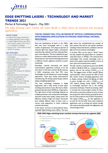
1575. Principles of Laser Dissection and Catapultinget al., 2004; Wu et al., 2003). While the above work was performed utilizing ns laserpulses (mostly at UV wavelengths), several researchers employed fs pulses forbiofilm and DNA printing (Karaiskou et al., 2003; Zergioti et al., 2005) andshock wave induced cell isolation, (Hosokawa et al., 2004). Laser-induced forwardtransfer with fs pulses was found to be more directional than with ns pulses (Zergiotiet al., 2003).The present study focuses on the investigation of LMD and LPC using UV nslaser pulses because this technique is widely used in many laboratories. It is the goalto elucidate the mechanisms and potential side eVects of LMPC in both dry andliquid environments (i.e., for histologic specimens and living cells). On the basis ofthis analysis, strategies for an improvement of the two techniques will be discussed.II. Features of the Microbeam System and Materials UsedWe used a PALM microbeam system equipped with an N2 laser (l ¼ 337nm)emitting pulses of 3-ns (FWHM) duration. The laser beam is coupled into aninverted microscope (Zeiss Axiovert 200) with a motorized, computer-controlledstage. The microscope objectives used in this study were Zeiss LD Plan-Neofluar40 /0.6 corr, Plan Neofluar 20 /0.5, Fluar 10 /0.5, and Fluar 5 /0.25. The UVabsorbing polymer foil mounted on the glass slides carrying the histologic sections(Fig. 1) consists of polyethylene naphthalate (PEN) and is 1.35-mm thick.An energy calibration (Fig. 2) showed that the relation between the setting at thecontrol box and the actual energy transmitted through the objectives is logarithmic.The transmitted energy is largest for objectives with small magnification because1005 10 20 10Energy (mJ)40 10.10.011E-30204060Energy setting80100Fig. 2 Pulse energy transmitted through the microscope objectives for diVerent settings at the lasercontrol box of the PALM microbeam in semilogarithmic representation.
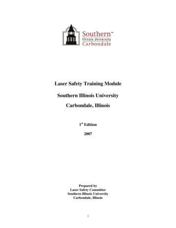
Alfred Vogel et al.158they possess large optical pupils that transmit the laser beam with little or novignetting. The focal spot sizes were measured using a knife-edge technique, asdescribed by Sasnett (1989) and Siegmann et al. (1991). The result for the40 objective is shown in Fig. 3A. Because of the poor quality of the N2 laserbeam (Fig. 3B and C), the spot diameter (4.2 mm up to 1/e2 irradiance values) ismore than six times larger than the diVraction limited focus diameter. Nevertheless,the hot spot visible in the center of the far-field beam profile in Fig. 3C allows toproduce relatively fine eVects if energies very close to the ablation threshold areemployed. In the present generation of microbeam systems, the N2 laser has beenreplaced by a frequency-tripled Nd:YAG laser emitting at l ¼ 355 nm that exhibitsAB12Beam radius (mm)108642 10C 505Position on the optical axis (mm)10DFig. 3 (A) Spot size of the N2 laser beam focused through the 40 objective, (B) near field and(C) far-field profiles of the N2 laser beam, and (D) far-field beam profile for the frequency-tripled Nd:YAG laser.
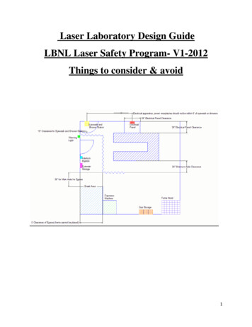
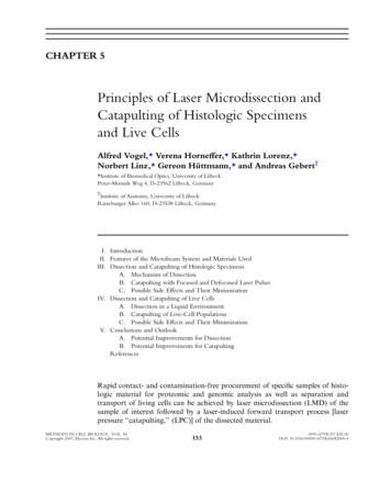
1595. Principles of Laser Dissection and Catapultinga much better beam profile, as shown in Fig. 3D, and thus makes it possible toachieve a nearly diVraction limited focal spot size.The transmission at l ¼ 337nm of cells, histologic material, and the polymerfoils mounted below the histologic sections were measured in the microbeam setupusing an Ophir PD10 detector with 1-nJ sensitivity and in a spectral photometer.All measurements were performed at low irradiance where nonlinear absorption isnegligible. The measurements on the optical properties of the cultured cells [Chinesehamster ovary (CHO) cells] were performed on a single, confluent cell layer.The determination of the optical properties of the PEN foil required measurementswith an integrating sphere, since PEN scatters strongly at l ¼ 337nm. For PEN, wemeasured total transmission and reflection as described by Vogel et al. (1991), andcalculated the absorption coeYcient ma and scattering coeYcient ms using theKubelka Munk theory (Cheong et al., 1990; Star et al., 1988). The eVective attenuation coeYcient meV and optical penetration depth d were then obtained by meansof the relation (Jacques, 1993):d¼11¼meff f3ma ½ma þ ms ð1 gÞ g1 2ð1Þassuming a value of g ¼ 0.5 for the scattering anisotropy coeYcient that is representative for moderate forward scattering in single scattering events (Cheong et al.,1990).The heat capacity of the polymer foil and the histologic specimens were determined by diVerential scanning calorimetry (DSC) in comparison with a sapphirestandard, and the dissociation temperatures were obtained through thermogravimetric analysis (TGA), that is, by measuring the weight loss as a function oftemperature. As an example, Fig. 4 shows the DSC and TGA data for PEN foil,the polymer material mounted on microscope glass slide on which the histologicspecimens are usually placed. Table I presents a summary of the measurementresults for the optical and thermal material properties of materials relevant forLMD and LPC of cells and histologic materials.III. Dissection and Catapulting of Histologic SpecimensA. Mechanism of DissectionIt has been shown recently that cell surgery using pulsed visible and near-IRirradiation is plasma mediated, that is, based on nonlinear absorption via multiphoton and avalanche ionization. The irradiances required for cell surgery with nslaser pulses are 109 W/mm2, just as the optical breakdown threshold in water(Venugopalan et al., 2002). For fs laser pulses, both the required irradiance fordissection and the threshold irradiance for optical breakdown in water are abouttwo orders of magnitude larger while the breakdown energy is about three ordersof magnitude smaller (Vogel et al., 2005a).
160Alfred Vogel et al.Fig. 4 Thermal properties of PEN foil. (A) Temperature-dependent heat capacity Cp. The peak at269 C indicates an endothermal melting transition, and the rise above 400 C is due to dissociation. (B)Temperature-dependent weight loss for a slow heating rate, with dissociation starting at 407 C andending at 500 C. The dissociation temperature defined by half of the total weight loss is 450 C. Forvery fast heating rates such as in pulsed laser catapulting, it will probably be higher because dissociationis a rate process that depends on both temperature and time.The dominant role of plasma formation for cell surgery using visible or near-IRwavelengths is not surprising because the linear absorption of water and biomolecules in this region of the optical spectrum is very small (Litjens et al., 1999; Vogeland Venugopalan, 2003). Our present study revealed that plasma formation plays akey role also for the dissection of cells at UV-A wavelengths. Although the absorption increases with decreasing wavelength, it is still fairly small at l ¼ 337nm
Table IOptical Properties at 337 nm and Thermal Properties of Cells, Histologic Material, Polyethylene Naphthalate (PEN) Polymer Foil,Glass, and WaterMaterialSamplethickness (mm)Transmission(%)Glass slidePEN-foil10001.3594.7T ¼ 20.5R ¼ 22.4Teflon foilH&E-stainedhistol.specimenCHO cellsWater 25 595.87–35(15.7) 593.8ExtinctioncoeYcientmeV (cm 1)Opticalpenetration depthd (mm)Average heatcapacity (kJ/K/kg)Dissociationtemperature( C)Heatconductivity(W/m/K)Density(W/m*K)0.55ma ¼ 3,520ms ¼ 17,370meV ¼ 01.07 0.425001.395801.9–4.8(2.7)1.03.2–340 0.2 0.52200 10001270.0172795.8 1054.04.187150–3003000.598 1000998All transmission data are corrected for specular reflection, that is, they represent purely the transmission of the sample. The optical parameters for stainedhistologic specimen cover a certain range given by variations in staining. The values in brackets were used for the temperature calculation is Section III.C.1.Sources for data not measured in this study are water absorption, Litjens et al. (1999); heat conductivity, heat capacity, and density of water, glass, PEN, andTeflon, Kuchling (1991); density of PEN, www.m-petfilm.com. The dissociation temperature of water corresponds, in the present context, to the superheatlimit in bubble-free liquid water (Vogel and Venugopalan, 2003), and the dissociation temperature of cells corresponds to their heterogeneous nucleationthreshold (Neumann and Brinkmann, 2005; Simanowski et al., 2005).
Alfred Vogel et al.162(the optical penetration depth is about 80 mm, see Table I) and even smaller at355 nm. Therefore, the ablation threshold in unstained cells was found to be onlyslightly smaller than the threshold for the formation of luminescent plasma, asshown in Fig. 5A.Stained histologic specimens and the PEN polymer foil have a much largeroptical absorption coeYcient than unstained cells (see Table I). For these materials, the ablation threshold is thus considerably lower than the plasma formationthreshold (Fig. 5A). It has previously been speculated that ablation of biomaterialat the N2 laser wavelength of 337 nm is based on photochemical dissociation(Schütze and Lahr, 1998). However, this is unlikely because indications for a relevantcontribution of photochemical eVects to ablation have been found only at muchshorter wavelengths, for example with ArF laser pulses at l ¼ 193nm while they werecompletely absent with XeCl excimer laser pulses of 308-nm wavelength (Vogel andVenugopalan, 2003). Therefore, we assume that ablation based on linear absorptionat l ¼ 337nm is a purely thermal process.Figure 5A indicates that dissection of histologic specimens by N2 laser pulsescould, in principle, be performed by ablation without any contribution of plasmaA 5Irradiance (GW/cm2)Glass slideAblation thresholdPlasma threshold43Cells2H&E stainedspecimen1002000PEN foil4000 6000 8000 10,000 12,000Extinction coefficient (cm 1)BFig. 5 (A) Thresholds for ablation and plasma formation at 337nm for various materials. (B) Imageof plasma luminescence during microdissection of histologic specimens (6 pulses of 4.6 mJ). The plasmaluminescence is blue at the target surface but turns red at larger distances where the temperatures aresmaller and the corresponding wavelength of blackbody radiation is longer. The blue light emissionadjacent to the laser focus is caused by fluorescence of the PEN polymer foil.
5. Principles of Laser Dissection and Catapulting163formation because the ablation threshold (0.15 mJ with NA ¼ 0.6) is slightly lowerthan the threshold for plasma formation (0.3 mJ). However, because of the smallablation eYciency close to the threshold for material removal this dissection modewould require very many pulses which are not viable at the relatively small laserrepetition rate of 30 Hz. Therefore, pulse energies of about 0.5 mJ are commonlyused and focused through a 40 , NA ¼ 0.6 microscope objective. That energy islarger than the threshold for plasma formation, and dissection is thus accompaniedby blue plasma luminescence as visible in Fig. 5B. The slightly disruptive action of theplasma expansion helps to achieve clean cuts without any bridges remaining betweenthe parts to be separated. We conclude that dissection of histologic specimens usingUV laser pulses is based on plasma formation (i.e., nonlinear absorption) initiated bylinear absorption.B. Catapulting with Focused and Defocused Laser Pulses1. Driving Forces for Catapulting with Focused PulsesThe mechanisms of catapulting of histologic specimens and live cells wereanalyzed by time-resolved photography. Similar techniques have been employedpreviously for the analysis of other laser-induced transport processes (Koulikovand Dlott, 2001; Lee et al., 1992; Nakata and Okada, 1999; Papazoglou et al.,2002; Rau et al., 2004; Young et al., 2001), and LPC by laser pulses focusedthrough an upright microscope has been documented by high-speed cinematography with 1-ms interframing time (Elvers et al., 2005). We achieved a temporalresolution better than 100 ns by using single frame photography with increasingtime delay between catapulting laser pulse and the instant at which the photograph was exposed (Vogel et al., 2007). The catapulted specimens were imagedin transillumination using the light of a plasma discharge lamp with 20-ns duration(Nanolite). The total magnification of the imaging system was 44 , and the images were detected using a 6-megapixel digital camera. The laser-produced pressurewaves were visualized by means of a sensitive dark-field Schlieren technique (Vogelet al., 2006). A frequency-doubled Nd:YAG laser beam coupled into a 300-m-longmultimode fiber to destroy temporal coherence served as speckle-free light source forphotography with 16-ns exposure time. To reduce the background noise and enhancethe visibility of the laser-produced shock wave, a reference image was taken at timet 0 and subtracted from each image recorded after the release of the catapultinglaser pulse. The initial phase of the catapulting process was documented with timeincrements of 2–60 ns. The high time resolution allowed to deduce the laser-producedpressure from the speed of the resulting pressure waves (Lorenz, 2004; Vogel et al.,1996b, 2007).The specimen is usually located on a PEN foil backed by a transparent substrate(glass slide). Laser pulse energies commonly used for catapulting are larger than theenergies employed for LMD that was already shown to rely on plasma formation.It is thus obvious that catapulting with focused laser pulse is driven by plasma
Alfred Vogel et al.164formation in the confined space between specimen and substrate. The initial catapulting dynamics under these conditions is shown in Fig. 6. The luminescent plasmadriving the catapulting is visible in all frames. Immediately after the laser pulse,small debris particles are ejected with high velocity, and after 270 ns, the specimen isalready clearly detached from the substrate surface. At the location of plasmaA30 ns160 ns270 ns520 ns590 ns800 ns3.0 ms4.3 ms5.4 ms100 mmBFig. 6 (A) Initial phase of the catapulting dynamics of a specimen with 80-mm diameter from a paraYnsection. 40 objective, NA ¼ 0.6, and E ¼ 10 mJ. (B) Enlarged view of the specimen after 1.7 ms showingthe luminescent plasma driving the specimen, and the blue fluorescence of the PEN polymer foil.
1655. Principles of Laser Dissection and Catapultingformation, a hole is produced in the specimen, which is clearly visible in the imagetaken after 5.4 ms.The pressure wave produced by the expansion of the laser plasma is shown inFig. 7. An evaluation of the photographic series provided quantitative information on the propagation distance of the laser-produced pressure wave, the ejecteddebris, and the catapulted specimen as a function of time that is presented inFig. 8. The initial velocity of the pressure wave amounts to 26,000 m/s, which is76 times larger than the normal sound velocity in air and thus indicative for astrong shock wave. The plasma pressure driving the shock wave can be derivedfrom the initial shock wave velocity vs using the relation (Landau and Lifschitz,1987):" #7vs 21 ð2Þp0pplasma ¼6 c06Here c0 ¼ 345 m/s denotes the normal sound velocity in air and p0 ¼ 0.1 MPais the atmospheric pressure. The initial laser-produced pressure was found tobe 670 MPa, a typical value for plasmas generated in a confined geometry2 ns4 ns6 ns34 ns56 ns76 ns118 ns168 ns224 ns100 mmFig. 7 Dark-field photographic series showing the first 225 ns of the catapulting dynamics. A specimenwith 80-mm diameter from a paraYn section was catapulted using a 40 objective, NA ¼ 0.6, andE ¼ 10 mJ. The movement of the ejected particles and the propagation of the laser-induced shock wavecan be recognized, followed by the detachment of the specimen after 100–200 ns.
166Alfred Vogel et al.Fig. 8 Propagation distance of the laser-produced shock wave (A), the ejected particulate debris (B), andthe catapulted specimen (C) as a function of time. From the slope of the d(t) curves, initial velocities of(A) 26,000 m/s, (B) 2200 m/s, and (C) 178 m/s can be deduced, which corresponds to (A) 76 , (B) 6.4 , and(C) 0.52 the sound velocity in air. 40 objective, NA ¼ 0.6, specimen diameter 80 mm, and E ¼ 10 mJ.
1675. Principles of Laser Dissection and Catapulting(Anderholm, 1970; Fabbro et al., 1990). Similar pressure values were also obtained by analyzing the acceleration of the debris flying oV from the laser focusthat is visible in the dark-field images of Fig. 7. Its peak velocity after a 10-mJ laserpulse is already reached at the end of the laser pulse (i.e., after 3 ns) and amounts to2200 m/s (Lorenz, 2004).The initial specimen velocity in Fig. 8C is 180 m/s. In the early days of LPC, ithas been speculated that the specimens are driven by the light pressure (Schützeand Lahr, 1998). We can check the validity of this hypothesis by comparing themeasured specimen velocity with the speed that can be imparted by the lightpressureplight ¼Icð3ÞHere I is the irradiance in the illuminated laser spot and c is the vacuum velocityof light. The accelerating force exerted by the light pressure acts during the laserpulse duration and the final velocity reached can be calculated considering themass of the specimen. The calculation yields v ¼ 0.9 mm/s for a specimen of 80-mmdiameter, 7-mm thickness, and a mass density of 1 g/cm3 that is catapulted by a10-mJ pulse (parameters as in Fig. 8). This value is five orders of magnitude smallerthan the actual velocity. The pressure exerted by the photons in the laser pulse,which is the working mechanism in laser tweezers (Ashkin, 1986; Greulich, 1999;Schütze and Clement-Sengewald, 1994), thus plays only a negligible role in LPC.We showed that catapulting with focused pulses relies on the pressure producedby confined plasma formation. However, in spite of the large pressures involved,the catapulted specimens in Fig. 6 show little bending or other deformations. Thisis due to the fact that the large pressure at the focus is in vertical direction rapidlyreleased by the hole formation in the specimen. In horizontal direction, the shockwave spreads across the specimen diameter within about 20 ns (Fig. 7). This way,it produces an approximately homogeneous elevated pressure below the specimenthat lifts oV from the substrate after about 100–200 ns (Figs. 6 and 7). In Fig. 6,one can see that the horizontal pressure wave also propagates under adjacent partsof the histologic section and transiently detaches them from the substrate for a fewmicroseconds. The average pressure under the entire catapulted specimen duringthe acceleration phase of about 100 ns can be derived from the velocity reachedafter this phase, the acceleration time, and the estimated mass of the specimen(Lorenz, 2004). It amounts to about 18 MPa for the parameters in Fig. 8, which isconsiderably less than the peak pressure within the laser plasma of 670 MPa.In some cases, the histologic specimens to be catapulted are mounted on a foilwithout backing by a glass substrate. Without confinement by the glass substrate,the plasma or ablation plume can freely expand. In this case, catapulting reliesmerely on the pressure produced by ablative recoil. Therefore, it is smaller than forplasma generation or ablation in a confined geometry, as shown in Fig. 9. Theimpulse coupling eYciency in laser ablation was theoretically analyzed by Phippset al. (1988) and Dingus (1992, 1993). It was predicted to be smaller without
168Alfred Vogel et al.Fig. 9 Comparison of the velocities of specimens on a foil (A) with and (B) without backing by a glasssubstrate. Each data point refers to the average of five measurements. Specimen diameter 80 mm, 40 objective, NA ¼ 0.6, and E ¼ 5 mJ.confinement of the ablation products, in agreement with our present observationsand with results for aluminum foils obtained previously by SheYeld et al. (1966).The dependence of the velocity on laser pulse energy for specimens that arebacked by a gl
during LPC Sc( h u tze and Lahr , 1998). Thes e advanceme nts, toget her with an increa sed demand for separat ion techni ques due to the refinement s of proteom ic and genomi c analys is, and the pro of that LMPC is c ompatible with DNA and RNA recover ySch( u tze and Lahr , 1998) paved the way of LMPC into the market