Transcription
EPILOG LASER16371 Table Mountain ParkwayGolden, Colorado 80403Phone 303-215-9171 - FAX 303-277-9669www.epiloglaser.comMachine Type:Zing Laser EngraverProcedure Title:Aligning the Laser BeamTools Required:# 1 Phillips Screw Driver3/32 Hex (Allen) wrenchTarget, was supplied with engraverMasking tapeWARNING: This procedure requires that the laser be operated with the protective coversremoved. While the laser power levels are reduced from those of normal operation, they aresufficient to inflict eye injury or burns.WARNING: The operator MUST ENSURE that all persons present during the performanceof this procedure are equipped with adequate eye protection (Lexan safety glasses,eyeglasses or goggles), and that no one looks or places any part of his or her body into thepath of the laser beam.
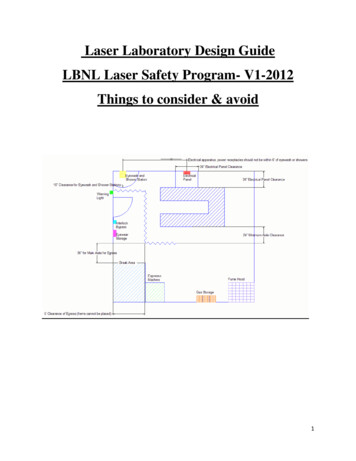
Conventions:The right hand side of the machine is where the control panel is located. When facing the front of themachine, left is your left, and right is your right (toward the control panel).To make the process easier to understand the corners of the engraving area will be labeled as follows:CornerLEFT FRONTLEFT REARRIGHT FRONTRIGHT REARPosition1234Table Guides42Corner Numbers13The table positions shown above are sorted based on their distance from the laser tube.Because the laser beam diverges, or spreads out as it travels from the laser tube to the focal lens, theburn marks on the tape WILL get larger the further the lens is from the laser tube.There are 3 mirrors used to adjust the laser beam. These mirrors are shown in the picture below.These mirrors will be referred to throughout the alignment procedures.MirrorLaser Mirror #1 (lower)Laser Mirror #2 (Upper)Y-Axis MirrorPosition Controlled123 & 4**Position #4 is on the same path as positions #2 and #3, thus when those positions arealigned, #4 will automatically fall into place.
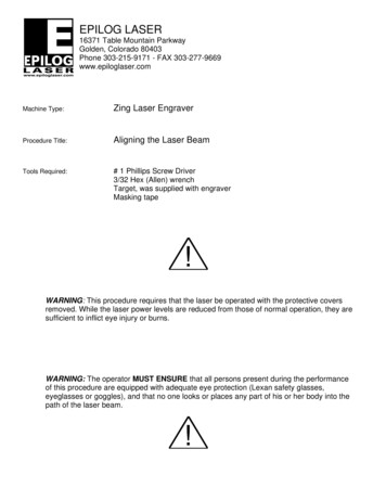
Pre-Alignment TestingThis portion of the alignment procedure determines if the laser and the Red Dot Pointer are in alignment. Thisis a critical step, as it allows us to use the Red Dot pointer as a visual reference and greatly limits the amountof time that the laser is operated with the side covers removed.1. Set up your Corel page so it is equal to the size of your table, 16x12 in this case.2. Create a small ¼ inch by ¼ inch black filled box in the Upper right hand corner of the page and sendthe job to the engraver with very low speed and very low power.3. Install the alignment target in to the lens carriage and place a small piece of tape over the surface ofthe target as shown in picture 1.Picture 14. Once the job is started, be prepared to press the stop button to disable the laser beam once the tapestarts to discolor. This will limit the amount of burning on the tape and make this process a little easier.5. Because each laser is different, you may need to experiment with power settings needed to mark thetape.6. Once the tape has discolored, depress the reset button to move the carriage back to the home position.Depress the “X/Y off” button to disable the axis. You can now move the X/Y carriage around the 4corners of the table.7. Depress the “Pointer” button to turn on the red dot pointer.
8. Move the lens carriage to the lower right hand side of the engraver and inspect the position of the reddot compared to the position of the mark that the laser beam left on the tape. If the laser and the reddot are coaxial or aligned, the red dot will be over the mark left by the laser.9. If the red dot pointer is over the mark left by the laser, begin the alignment procedure at STEP #6 of theLaser Alignment Procedure. If the red dot is not over the mark left by the laser, start at STEP #1 of theLaser Alignment ProcedureLaser Alignment Procedure1. Remove the left hand side panel from the engraver. Do this by removing the 4 Phillips screws whichsecure the panel in place. These screws are shown in pictures 2a and 2b.Picture 2a
Picture 2b2. Behind this panel you will find the laser tube. Attached to the end of the laser tube is the Red Dot pointer.The Red dot pointer is identified by the arrow shown in Picture 3.Picture 33. The red dot pointer is mounted in an adjustable ring. Around the outside of this ring are three adjustmentscrews. Picture 4 below shows the location of the Red Dot pointer adjustment screws.Picture 4
4. Use the adjustment screws located on the Red Dot mount to change the position of the Red Dot on thetarget. Make the necessary adjustments to move the Red Dot pointer over the top of the mark left by thelaser. Picture 4 below shows which direction you can expect the red dot to move based on the adjustmentscrew selected and the direction that it is turned.Picture 4*The White Dot denotes the screw that is beingturned and the white arrow indicates the direction thatthe screw is turned. The image to the right, with the black arrowacross the target indicates which direction the red dot will moveNote: Turning the screw in very small increments is all that is needed to move the pointerconsiderably. Over-turning a screw can result in moving the red dot completely off of the lenstarget.5. The laser and the Red Dot pointer are now aligned.
Throughout the rest of this procedure the Red Dot pointer will be used as a visual reference to aid in thealignment process. There should be no need to operate the laser to complete the remainder of this procedure.6. Invoke the Red Dot pointer by depressing the “Pointer” button on the engravers display panel and makesure to remove the tape from the target that was used previously to check the alignment with the burn.7. Disable the X/Y axis by pressing “X/Y OFF” button. This will allow you to move the lens carriage aroundthe engravers table by hand.8. Directly to the right of the Laser/Red Dot assembly is the periscope. This periscope contains Mirror #1and Mirror #2. The periscope is shown in picture 6 below and is identified by the arrow.Picture 69. Mirror 1 is identified in picture 7 below.Picture 7
10. On the back of each mirror mount are three 3/32 Allen (Hex) screws. The adjustment screws for mirror 1are shown in the picture 8 below.Picture 811. Move the lens carriage to table Position #1 and verify the location of the red dot pointer on the target. Ifthe red dot is not aligned to the center of the target, use the Mirror # 1 and the diagram below to adjustthe red dot pointer until it is aligned to the center of the target. The red dot need only be in the inner ringof the target, like what is shown in Picture 9 below.Picture 9
12. The next step is to verify the alignment in all 4 corners of the table. Slowly move the lens carriage fromPosition #1 to Position #2, observing the location of the red dot pointer on the target. The red dotpointer should stay within the center ring of the target. If the red dot pointer is not aligned in Position #2,use the Mirror #2 and the diagram below, Picture 10, to align the red dot to the center of the target.Picture 10Note: If an adjustment was made to mirror #2, you must go back to Position #1 and recheckthe alignment at that position and make any necessary adjustments. You will then recheckand align Position #2 and Position #1 again, alternating between the two positions andrechecking alignment and adjusting each positions corresponding mirror until both positionsare aligned13. Move the X-axis assembly back to position 1 and verify that the Red Dot pointer has not moved from thecenter of the target. If the Red dot is in the center proceed to the next step. If the red dot pointer is not inthe center of the target return to step 11 and realign for position 1.
14. Next, move the lens carriage to Position #3 on the table and check the alignment of the red dot on thetarget. If the red dot is not in the center at this position, use Steering Mirror #3 and the diagram below,Picture 11, to adjust the red dot pointer to the center of the target.Steering Mirror Adjustment DiagramPicture 1115. Once Position #3 is aligned you can remove the target from the lens carriage and reset the engraver andproceed to run your jobs.If you are still having difficulty or uneven engraving either from the top to bottom or left to right, or if you have anyquestion, please contact Epilog’s Technical Support at the numbers listed below.Phone 303.215.9171Fax303.531.7594E-Mail tech@epiloglaser.com
Laser Alignment Procedure 1. Remove the left hand side panel from the engraver. Do this by removing the 4 Phillips screws which secure the panel in place. These screws are shown in pictures 2a and 2b. Picture 2a . Picture 2b 2. Behind this panel you will find the laser tube. Attached to the end of the laser tube is the Red Dot pointer.