Transcription
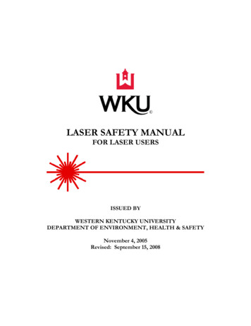
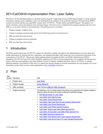
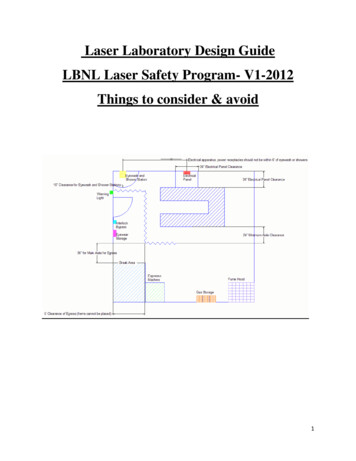
Chapter 4Longitudinally Excited CO2 LaserKazuyuki UnoAdditional information is available at the end of the chapterhttp://dx.doi.org/10.5772/485251. IntroductionIn the mid-infrared region (3 – 30 μm), there are only several kinds of commercial laser asshown in Fig. 1. A CO2 laser is very important because the CO2 laser emits high outputenergy and various pulse shapes at the wavelength region between 9.2 μm and 11.4 μm witha high absorptivity in many substances. The first CO2 laser was developed by C. K. N. Patelin 1964 and had a continuous output power of a few milliwatts (Patel, 1964). In 1968, thepulsed CO2 laser was developed by A. E. Hill and had a few joules (Hill, 1968). Nowadays,various types of CO2 lasers have been developed. The characteristics of CO2 laser pulses aredetermined by the discharge tube structure (a longitudinal excitation scheme like Fig. 2 (a)or a transversal excitation scheme like Fig. 2 (b)), the discharge types (DC discharge, RFdischarge, or pulsed discharge) and the oscillation system (CW oscillation, Q-switchedoscillation, or pulsed oscillation).Figure 1. Mid-infrared commercial lasers (Photonics.com). Unit is μm. 2012 Uno, licensee InTech. This is an open access chapter distributed under the terms of theCreative Commons Attribution License (http://creativecommons.org/licenses/by/3.0), which permitsunrestricted use, distribution, and reproduction in any medium, provided the original work is properly cited.
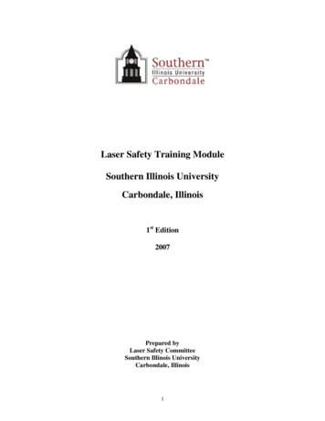
116 Laser Pulses – Theory, Technology, and Applications(a)(b)Figure 2. Excitation system. (a) Longitudinal excitation system. (b) Transversal excitation system.In the CW oscillation and the long pulse oscillation (a pulse width of 10 μs – 10 ms), a lowpower CO2 laser ( 10W) is used as a medical laser like tooth and skin treatments. A CO2laser emitted 20 – 100 W is used for cutting a nonmetallic substance like a film, cloth, leather,paper, rubber, a plastic, acrylics, etc. A high power laser emitted 100 – 400 W is used forcutting metal, glass, and ceramics. A short pulse CO2 laser that emits an output energy of afew joules and a pulse width of about 100 ns is used for puncturing and patterning of anonmetallic substance, removal of surface polymer material which does not give a damageto a metal board, and etc. Specially, a large and high output CO2 laser called “Lekko VIII”that emitted an output energy of 10 kJ and a pulse width of 1 ns was developed in Instituteof Laser Engineering, Osaka University, Japan, 1981 (Yamanaka et al, 1981). Recently, theCO2 laser attracts attention as a driver laser for a Laser-Produced-Plasma Sn-EUV source(13.5 nm) and a excitation laser for a Terahertz laser (CH3F, C2H2Cl, CH3OH, D2O, and etc.,30 – 300 μm) (Ueno et al, 2007; He et al, 2010).
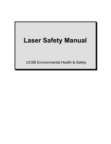
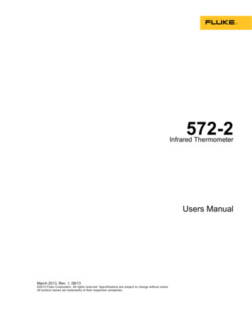
Longitudinally Excited CO2 Laser 1172. Principle of CO2 laserThe CO2 laser oscillates in the vibrational level of CO2 molecular. The CO2 laser has about100 oscillation lines at the center of 9.6 μm and 10.6 μm between 9.2 μm and 11.4 μm. Fig. 3shows the energy diagram of CO2 laser. Generally, the CO2 laser is pumped by glowdischarge in the low mixed gas (CO2, N2, He, and etc.) pressure. The N2 serves to improvethe output energy and the efficiency due to the energy transfer from the vibrational level ofN2 to the upper laser level of CO2. However, in the short pulse oscillation, N2 causes a laserpulse tail because of the long lifetime of the vibrational level of N2. The He serves to makethe discharge uniform. The CO2 molecular is efficiently pumped by very low electrontemperature because the energy of the laser upper level 001 is 2349.2 cm-1 and the energyrequired for excitation of CO2 molecule is about 0.28 eV. However, generally, the CO2molecular pumped by the higher electron temperature than 0.28 eV because of an electricalgradient to sustain the discharge. The CO2 laser oscillates at 10.6 μm band (001 – 100transition) and 9.6 μm band (001 – 020 transition) and has about 100 oscillation lines becauseof the P branch and the R branch related to the rotational level. The laser lower levels of 100and 020 are relaxed by the collision with the CO2 molecule of ground state. The 010 levelserves as a bottleneck. But the thermal relaxation of the 010 level is accelerated by thecollision with other molecular, He atom and the laser tube wall. Then, the 010 level returnsto the ground state. Therefore, in the efficiently laser oscillation, the N2 molecular thatsupplies the upper laser level of CO2 and media like He that eases the lower laser level ofCO2 are essential. However, in the low-pressure pulse-discharge at the low repetitiveoperation, He may be unnecessary.Figure 3. Energy diagram of CO2 laser.
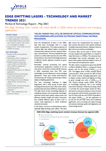
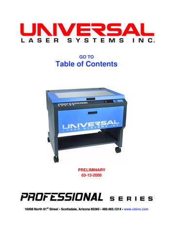
118 Laser Pulses – Theory, Technology, and Applications3. Longitudinal excitation schemeIn the longitudinal excitation scheme, the excitation discharge is in the direction of the laseraxis. This system was used in the early stage of development of lasers such He-Ne lasers(633 nm), N2 lasers (337 nm) and CO2 laser (9.2 – 11.4 μm). In this system, a dielectric tubewith the small inner diameter (1 – 2 cm in CO2 lasers) and the long length ( 30 cm in CO2laser) is used as a discharge tube. Metallic electrodes are attached to each end of the tube.The long discharge length provides a high breakdown voltage ( 20 kV) at a low gaspressure ( 10 kPa). Therefore, this system does not require a high gas-pressure vessel.Moreover, this laser may oscillate at narrow spectral width because the low-pressureoperation produces the small pressure broadening. A uniform discharge can be obtainedeasily because of the fast electron drift velocity (the long mean free path) of the low pressureoperation; additionally, the discharge uniformity is not affected by residual charges in thelongitudinal excitation because a discharge takes place in a discharge tube with a longlength and small inner diameter. In a RF discharge, an electronic trapping occurs. A uniformdischarge takes place because electrons vibrate by the high-frequency electric field and aretrapped between the discharge gaps. In a pulsed discharge, a uniform discharge takes placeby a diffuse streamer discharge is formed by diffusing uniformly and progressing the minutespark discharge with which an avalanche and optical ionization are combined (Fig. 4).Figure 4. Longitudinally pulsed discharge.
Longitudinally Excited CO2 Laser 119Figure 5. Longitudinally pulsed discharge with strong preionization.Therefore, the longitudinal excitation scheme does not require a pre-ionization device likeUV and X-ray source. On the other hand, when the pre-ionization is required in the highpressure operation ( 1 atm), the discharge tube is covered with Al foil (Fig. 5, 6) (El-Osealyet al, 2002b; Uno et al, 2009; Uno et al, 2012a). A corona discharge occurs along the tube wallbefore the main discharge to serve as pre-ionization. Therefore, nothing is put in thedischarge tube. In the longitudinal excitation scheme without pre-ionization, a gas lifetimeis long. The gas lifetime is a phenomenon in which the laser output energy decreases withoperation time in a sealed-off operation. Impurities increases with time in the dischargetube, UV and X-ray for the pre-ionization cannot reach the center part of the dischargespace, the uniform discharge cannot take place, the localization of the discharge occurs, and
120 Laser Pulses – Theory, Technology, and ApplicationsFigure 6. Longitudinally pulsed discharge with simple preionization.the laser output energy decreases. Therefore, this scheme without the pre-ionization issuitable for the long lifetime operation. Additionally, in this scheme, the perfect hard-sealeddischarge tube without a gasket packing like a rubber O-ring is producible because thestructure of the discharge tube is simple. Therefore, this scheme is suitable for the longlifetime gas laser. In fact, a low-output sealed-off CO2 laser has a CW oscillation or a highrepetition oscillation without a gas-flowing system and water-cooling system effectively.Additionally, in this scheme, the beam section of the laser is circular because the dischargetube is used a dielectric tube like a glass tube and a ceramics tube. All the optical elementsmay be circular. This scheme produces laser beam with good beam quality because thelength of optical cavity is long enough to the diameter of aperture (the inner diameter of thedischarge tube). Therefore, in the longitudinal excitation scheme, a high performance lasercan be developed with a simple, portable, and low-cost device.In the longitudinal excitation scheme, as shown in Table 1, various laser oscillation frommid-infrared to vacuum ultraviolet has been reported. In recent years, especially, new gaslasers, for example, a longitudinally excited CO2 laser with short laser pulse like TEA and Qswitched CO2 laser (Uno et al, 2009), a longitudinally excited N2 laser with the sameexcitation system as an excimer lamp (Uno et al, 2006), and a longitudinally excited F2 laserat low-pressure (total pressure of 40 Torr) (El-Osealy et al, 2002b) have been developed.
Longitudinally Excited CO2 Laser 121Figure 7. Characteristics of longitudinal excitation system.Table 1. Longitudinally excited gas lasers.4. Excitation systemThe shape of laser pulse depends on the discharge and oscillation types. The discharge typecan be divided into the DC (direct current) discharge, the RF (radio frequency) discharge
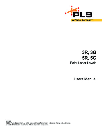
122 Laser Pulses – Theory, Technology, and Applicationsand the pulsed discharge. The oscillation type can be grouped into the CW (continuouswave) oscillation and the pulsed oscillation including Q-switched oscillation. The DC andRF discharge provides the CW oscillation basically and can provide the long-pulsedoscillation (the pulse width from several μs to several ms) by switching of excitationdischarge and the short-pulsed (giant-pulsed) oscillation (the pulse width of about 100 ns)by using Q switch. Although it is well known the pulsed discharge provides the long-pulsedoscillation, the pulsed discharge can provide the short-pulsed oscillation (the pulse width ofabout 100 ns and the pulse tail of several tens μs) like the Q-switched CO2 laser and a TEACO2 laser.4.1. DC dischargeFigure 8 shows a general longitudinally excited CO2 laser pumped by DC discharge. TheDC-CO2 laser commonly is used a high-voltage (a few tens kV) DC power supply and emitsthe CW power of several tens kW. The output power can control delicately by adjustment ofDC voltage.A discharge tube is made of a heat-resistant hard glass pipe with an inner diameter ofseveral mm and is the co-axial dual structure for cooling by water. Cooling improves theefficiency and output power of the laser oscillation by decreasing the plasma temperature.Additionally, high output power can be provided by a multi-path system folding back theoptical path in the resonator and a multi-beam system which uses multi-tubes. High powerDC-CO2 laser emitting CW power of 1 kW using 20 discharge tubes with the inner diameterof 9 mm and the length of 195 cm has been reported (Deshmukh & Rajagopalan, 2003).A low power CO2 laser can operate in a sealed-off mode. In a long-life sealed-off CO2 laser, agold catalyst is used to regenerate CO2 from the dissociation products formed duringdischarge (Tripathi et al, 1994). In the sealed-off CO2 laser, the laser beam (output power andbeam quality) is stable because discharge and the distribution of particles are uniform. In ahigh power CO2 laser, a gas-flowing system circulating fresh gas is used for preventing thedecrease of the oscillation efficiency by the deterioration of gas. The longitudinal excitationsystem has only an axially flowing type.Figure 8. Discharge tube with water jacket.
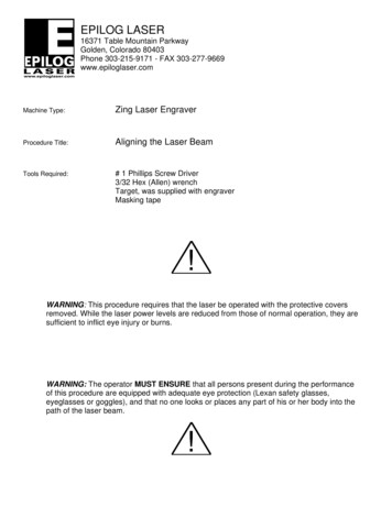
Longitudinally Excited CO2 Laser 123(a)(b)(c)Figure 9. RF discharge tube. (a) Longitudinal excitation (Lee et al, 2000). (b) Transverse excitation (Teraiet al, 1993). (c) Coaxial RF-CO2 laser (Bethel, 1998).
124 Laser Pulses – Theory, Technology, and Applications4.2. RF dischargeThe first CO2 laser by C. K. N. Patel used the RF discharge excitation, 27 MC/s (Patel, 1964).In the RF discharge excitation, the medium gas is pumped by a high-frequency voltage(typically 13.56 MHz). In this system, electrodes are able to be put on the outer wall ofdischarge tube. Thus, the electrodes are not sputtered and there are little degradation of gasand contamination of optical components. A compact high-output CO2 laser can bedeveloped by high discharge input-energy per unit volume. An electronic trapping providesgood pulse characteristics.However, generally, the RF discharge excitation scheme uses the discharge tube like Fig. 9.Fig. 9 (b) looks like the longitudinal excitation scheme, but is the transversal excitationscheme because the direction of discharge is perpendicular to the direction of a laser axis.In the low pressure region less than 10 kPa, the laser pumped by RF wave more than 0.1MHz emits CW and the laser pumped by RF wave less than 10 kHz emits pulse shapes.Generally, the pulse oscillation of RF-CO2 lasers is realized by switching of excitationdischarge and the duty ratio of ON and OFF (Nagai, 2000). Fig. 10 (a) is a example of normalpulses by chopping the CW output. In the axial flowing system, the gas existence time in thedischarge tube is long and the rise of gas temperature is large. It is difficult to keep the peakvalue of a pulse constant for a long time. Therefore, a narrow pulse shape called anenhanced pulse like Fig. 10 (b) or a super pulse like Fig. 10 (c) takes place.(a)(c)(b)(d)Figure 10. Images of RF-CO2 laser output (Nagai, 2000). (a) CW. (b) Normal pulses. (c) Enhancedpulses. (d) Super pulses.
Longitudinally Excited CO2 Laser 125In the slab RF-CO2 laser, commercial sealed-off CO2 lasers produces the broad output rangefrom CW 20 W to CW 1 kW and the high peak pulse oscillation of 2.5 kW at the pulse width50 μs at 1 kHz (Coherent, Inc., DIAMOND E-1000). In a compact fast axial flow CO2 laser,the output power of CW 2.1 kW has been reported (Biswas et al, 2010). Additionally, a lowpower CO2 laser pumped by AC discharge of 60 Hz whose frequency is lower than RFdischarge has also been reported (Lee et al, 2000).4.3. Q-switchA Q switch is a system to produce a giant pulse with a short pulse and a high peak power. AQ value is a standard of the resonator performance and is a ratio of a loss energy to a storageenergy in the cavity. It is hard to carry out a laser oscillation when a Q value is low, and it iseasy when a Q value is high. The Q switch rapidly decreases the high resonator losses, thatis, rapidly increases the Q value.A CW-CO2 laser using a Q switch produces a giant pulse with a pulse width from a few tensns to a few μs and a peak power of several kW. In a CO2 laser, the use of a mechanicalchopper, rotating mirror (Battou et al, 2008), electrooptical (CdTe) (Tian et al, 2005) oracoustooptical modulators (Xie et al, 2010), or saturable absorber (SF6) (Soukieh et al, 1999)has been reported.4.4. Pulsed dischargeA CO2 laser is easily oscillated by applying a high voltage pulse of about 20 kV to alongitudinal discharge tube filled by CO2 gas. Fig. 11 shows a longitudinally excited pulsedCO2 laser with a general and easy excitation circuit (Chung et al, 2002; Loy & Roland, 1977).A voltage pulse of several hundreds V is generated by a power supply and is fed to a stepup transformer. The high-voltage pulse of about 20 kV is directly applied to the dischargetube. The high-voltage pulse has a long rise time of about a few hundred μs because thetransformer with a large inductance is directly connected to the discharge tube. When theapplied voltage reaches the breakdown threshold, a discharge starts and the laser oscillates.The laser output energy depends on the discharge volume and the input energy. The laserpulse has a long width from several tens μs to several ms because the excitation circuitproduces a long and high voltage pulse and the discharge formation time is long. Forexample, the discharge tube with the length of 80 cm applied the high voltage pulse of 25kV and produced the output power of 35 W and the width of 3 ms at 60 Hz (Chung et al,2002).The longitudinally excited CO2 laser produces a short laser pulse like TEA-CO2 laser and Qswitched CO2 laser by a fast discharge. Fig. 12 shows a CO2 laser with a capacitor transfercircuit that is used for transversal excited excimer lasers and is known as a fast dischargecircuit (Miyazaki et al, 1986). A low-inductance storage capacitor Cs was charged up to DCvoltage of about 20 kV. A spark gap was switched by a trigger pulse from a trigger circuit,and the high voltage was transferred to a buffer capacitance Cb. When the voltage reached
126 Laser Pulses – Theory, Technology, and Applications(a)(b)Figure 11. Image of longitudinally excited long-pulse CO2 laser. (a) Schematic diagram. (b)Photograph.the breakdown threshold, a rapid main discharge took place in the discharge tube. The highvoltage pulse of a rise time less than 100 ns is applied to the discharge tube. Additionally, ahigh-voltage resistor is connected in parallel with the discharge tube. A low resistance actsas a shunt resistance and provides a rapid discharge.For example, in our study (Uno et al, 2009), the discharge tube was a ceramic pipe made ofalumina, with an inner diameter of 13 mm, an outer diameter of 17 mm, and a length of 45cm. The discharge tube was covered with an Al sheet. Therefore, the laser tube had a coaxialstructure for reducing the discharge impedance. An optical cavity was formed by a ZnSeoutput coupler with a reflectivity of 80% and a high-reflection mirror with a radius ofcurvature of 20 m. The distance between the output coupler and the mirror (i.e., the cavitylength) was 54 cm. In the excitation circuit, the storage capacitance Cs was 5.4 nF andcharged up to DC 20 kV, and the buffer capacitance Cb was 2.8 nF. The fall time of thedischarge voltage decreased from 32.8 μs (10 MΩ) to 0.97 μs (100 Ω). In the fast discharge,the gain increases gradually from the start of discharge. When the gain becomes enough
Longitudinally Excited CO2 Laser 127(a)(b)Figure 12. Longitudinally excited short-pulse CO2 laser with capacitor-transfer circuit (Uno et al, 2009).(a) Schematic diagram. (b) Photograph.after several μs from the start of discharge, the laser oscillates by a gain Q switch and a spikelaser pulse is formed. At that time, the main discharge finishes mostly. Low current after themain discharge and the energy transfer of the upper-level N2 with the long lifetime causesthe laser pulse tail of several tens μs. The pulse tail can be eliminated by eliminating theafter current or using of pure CO2 gas to eliminate the long N2 tail. Fig. 13 and 14 shows thelaser pulse in the discharge formation time of 32.8 μs and 0.97 μs, respectively, at the samedischarge tube with the inner diameter of 13 mm and the length of 45 cm and the same gaspressure of 2.9 kPa (CO2: N2: He 1: 1: 2) (Uno et al, 2009). Fig. 13 shows the laser pulse withthe spike pulse width of 103.3 ns, the pulse tail length of 61.9 μs, and the output energy of 50
128 Laser Pulses – Theory, Technology, and ApplicationsmJ by the discharge formation time of 32.8 μs. The pulse tail length was defined from theend of the spike pulse to the end of the pulse tail. Fig. 14 shows the laser pulse with thespike pulse width of 96.3 ns, the pulse tail length of 17.2 μs, and the output energy of 30 mJby the discharge formation time of 0.97 μs. These results showed the fast discharge causedthe decrease of the pulse tail.(a)(b)Figure 13. Laser pulse waveforms at slow discharge (discharge formation time of 32.8 μs and gaspressure of 2.9 kPa (CO2: N2: He 1: 1: 2)) (Uno et al, 2009). Intensity of vertical axis is normalized bypeak strength. (a) Overall waveform. (b) Magnified time scale view of spike pulse.(a)(b)Figure 14. Laser pulse waveforms at fast discharge (discharge formation time of 0.97 μs and gaspressure of 2.9 kPa (CO2: N2: He 1: 1: 2)) (Uno et al, 2009). Intensity of vertical axis is normalized bypeak strength. (a) Overall waveform. (b) Magnified time scale view of spike pulse.
Longitudinally Excited CO2 Laser 129The capacitor-transfer circuit like Fig. 12 developed for the transversely excited excimerlaser (Miyazaki et al, 1986). The capacitor-transfer circuit has a buffer capacitance in parallelwith the laser tube. The buffer capacitance functions to increase the applied voltage due tothe storage capacitance. However, because the transverse excitation scheme has a narrowelectrode gap and a small discharge impedance, a buffer capacitance is required to sustainthe discharge. On the other hand, the longitudinal excitation scheme has a wide electrodegap and a large discharge impedance and does not require a buffer capacitance to sustainthe discharge. Therefore, a circuit without a buffer capacitance, called a direct-drive circuitlike Fig. 15, has been developed (Uno et al, 2012a). Fig. 15 shows a longitudinally excitedCO2 laser with a direct-drive circuit (Uno et al, 2012a). A negative several hundreds V pulsewas generated by the power supply with a silicon-controlled rectifier and was fed to a(a)(b)Figure 15. Longitudinally excited short-pulse CO2 laser with direct-drive circuit (Uno et al, 2012a). (a)Schematic diagram. (b) Photograph.
130 Laser Pulses – Theory, Technology, and Applicationstransformer, which had a primary capacitance. First, a negative voltage pulse was generatedand was used to charge a storage capacitor through a rectifier. Then, a positive voltage pulsegenerated by the overshoot of the transformer was applied to the trigger electrode of thespark gap through a rectifier and a small capacitor. The storage capacitor was charged, thespark gap was switched, and the high voltage was applied to the laser tube. When thevoltage reached the breakdown threshold, a rapid discharge took place in the laser tube.This system produces a short pulse CO2 laser with a spike pulse.For example, in our study (Uno et al, 2012a), the laser tube was the almost same as the abovelongitudinally excited CO2 laser with the capacitor-transfer circuit. A different point was apartially preionization. Part of the discharge tube was covered with an Al sheet for a highdischarge starting voltage. In the excitation circuit, the primary capacitance Cp was 10.2 μFand the storage capacitance was 700 pF.(a)(b)Figure 16. Discharge voltage and CO2 laser pulse waveforms at 3.4 kPa (mixed gas, CO2 : N2 : He 1 : 1: 2) (Uno et al, 2012a). Black and gray lines represent laser pulse and discharge voltage, respectively. (a)Overall waveform. (b) Magnified time scale view of spike pulse.Figure 17. Discharge voltage and CO2 laser pulse waveforms at 2.2 kPa (pure CO2) (Uno et al, 2012a).Black and gray lines represent laser pulse and discharge voltage, respectively.
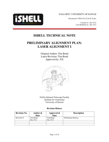
Longitudinally Excited CO2 Laser 131Fig. 16 shows the discharge voltage and laser pulse waveforms at the mixed gas (CO2: N2:He 1: 1: 2) pressure of 3.4 kPa. The discharge starting voltage was –60.2 kV, and the falltime of the discharge was 4.4 μs. The laser oscillation began 2.1 μs after the start ofdischarge. The laser pulse had a sharp spike, like that from TEA and Q-switched CO2 lasers.The spike pulse width was 147 ns (FWHM), and the pulse tail length was 35.5 μs. The laseroutput energy was 27.8 mJ, and the energy of the spike pulse part was estimated to be 3.1mJ. Fig. 17 shows the discharge voltage and laser pulse waveform at the pure CO2 gaspressure of 2.2 kPa. The discharge starting voltage was –60.8 kV, and the fall time of thedischarge was 1.9 μs. Laser oscillation began 0.6 μs after the start of discharge. The laseroutput energy was 0.4 mJ. The laser pulse contained a spike pulse only, and the width was93 ns (FWHM). Pulse-tail-free oscillation was realized by the use of pure CO2 gas.Figure 18 shows the simplest short-pulse longitudinally excited CO2 laser (Uno et al, 2012b).This system has a laser tube, a capacitor, a resister, and a pulse power supply with a lowvoltage silicon-controlled rectifier, and a set-up transformer only. The excitation circuit doesnot have a high-voltage switch; instead, the laser tube plays the role of the switch. Therefore,this system is almost same as the above long-pulse longitudinally excited CO2 laser.However, the step-up transformer has the fast rise time of about 3 μs. The fast transformerproduces the fast discharge which causes the short laser pulse.(a)(b)Figure 18. Short-pulse longitudinally excited CO2 laser with switchless circuit (Uno et al, 2012b). (a)Schematic diagram. (b) Photograph.
132 Laser Pulses – Theory, Technology, and ApplicationsFor example, in our study (Uno et al, 2012b), the laser tube was the same as the abovelongitudinally excited CO2 laser with the capacitor-transfer circuit (Uno et al, 2009). In theexcitation circuit, the primary capacitance Cp was 4.7 μF, the storage capacitance Cs was 700pF, and the resistor R was 10 MΩ.(a)(b)Figure 19. Discharge voltage and CO2 laser pulse waveforms at 3.8 kPa (CO2: N2: He 1: 1: 2) (Uno etal, 2012b). Black and gray lines represent laser pulse and discharge voltage. (a) Overall waveform. (b)Magnified time scale view of the start of discharge.(a)(b)Figure 20. Discharge voltage and CO2 laser pulse waveforms at 9.0 kPa (CO2: N2: He 1: 1: 2) (Uno et al,2012b). Black and gray lines represent laser pulse and discharge voltage, respectively. (a) Overallwaveform. (b) Magnified time scale view of the start of discharge.The long pulse oscillation takes place at gas pressure less than 3.8 kPa (CO2: N2: He 1: 1: 2)and the short pulse oscillation takes place at gas pressure more than 4.2 kPa. Fig. 19 showsthe discharge voltage and laser pulse waveforms at 3.8 kPa. The discharge voltage reached 25.8 kV at a raise time of 3.4 μs. In the low pressure, the breakdown voltage is low. Thedischarge starts when the applied voltage reaches the breakdown voltage. The fall time of
Longitudinally Excited CO2 Laser 133the main discharge was 2.8 μs. Laser oscillation took place 3.5 μs after the start of discharge.At this time, the discharge continues. The laser pulse did not have a spike pulse and is aconventional long pulse oscillation. The laser output energy was 10.0 mJ. The laser pulsewidth was the full width at half maximum (FWHM) of 17.7 μs and the pulse length of 88.3μs. Fig. 20 shows the discharge voltage and laser pulse waveforms at 9.0 kPa. The dischargevoltage reached -29 kV at a raise time of 3.1 μs. In the high pressure, the breakdown voltageis high and the applied voltage reaches maximum. The fast discharge is influenced by theimpedance matching of the excitation circuit and the discharge space. The fall time of maindischarge was 2.2 μs. The laser oscillation took place 7.5 μs after the start of discharge. Thelaser pulse had a spike pulse width of 218 ns and a pulse tail length of 16.7 μs. The laseroutput energy was 1.7 mJ. The energy of the spike pulse part was estimated to be 0.1 mJ. Itmay be necessary to improve the output energy for various supplications.5. Application5.1. CW and long pulse5.1.1. Medical applications80 wt% of soft biological tissue is water. Evaporation of water is a factor important for softtissue excision (Awazu, 2008). In laser irradiation, evaporation of water takes place at thecritical temperature of 101 K (Auerhammer et al, 1999). The evaporation of water causes thesoft tissue excision around the laser irradiation part. The tensile strength of soft tissue isabout 10 MPa on skin and several MPa on corneas, blood vessel, and muscle (Duck, 1990).The laser excision of soft tissue is carried out by a high mechanical power which causes aphase transition because 1 atm is about 0.1 MPa.A CO2 laser is effectively absorbed in water. In 9.2 – 11.4 μm of the CO2 laser wavelengthband, the absorption coefficient is 103 cm-1 (Zarrabi & Gross, 2011). Therefore, in the CO2laser, the penetration depth to soft biological tissue is short and about 50 μm. The CO2 laserevaporates only surface of soft tissue. Heat influence of deeper tissue is small and thedamage to normal tissue is minimally suppressed. Edema and sharp pain after an operationare little because the heat influence is restrictive. In the CO2 laser irradiation, shrink,dehydration, and carbonization of surface tissue take place. They cause water evaporationand vaporization of inner tissue. In this process, a protein denaturation layer of residualtissue is certainly generated. The denaturation layer functions as a solidification layer for anarrest of hemorrhage.At present, a CO2 laser of about 3 W a pulsed CW of (10 – 1000 ms and a super pulse of 0.1 –1 ms) is used for the skin treatment such as eliminating a mole, a wart, macule (Gotkin et al,2009) and wrinkle the aurinasal treatment such as hay fever and allergic rhinitis (Takeno etal, 2009), the eye treatment such as blepharochalasis and droopy eyelid (Rokhsar et al, 2008),and the dental treatment such as section and evaporation of soft tissue, hemostasis, andstomatitis (Zand et al, 2009). The advantages of CO2 laser surgery are alleviation of bleeding,pain and edema, and shortening of operation and recovery time.
134 Laser Pulses – Theory, Technology, and Applications5.1.2. Industrial applicationsWhen laser is irradiated to a material surface, a part is reflected by the reflectance of thematerial to the laser wavelength at the material surface, and the remainder is absorbed at thematerial surface. Then, the temperature of the material surface increases. A part of the heatis radiated by the heat radiation rate of the material, and the remainder conducts to insideby the heat conductivity of the material and makes the internal temperature increase. Thesurface temperature is fixed by the balance between the thermal energy lost by heatconduction and radiation and the thermal energy given by the laser. If the surfacetemperature does not
power CO2 laser ( 10W) is used as a medical laser like tooth and skin treatments. A CO2 laser emitted 20 - 100 W is used for cutting a nonmetallic substance like a film, cloth, leather, paper, rubber, a plastic, acrylics, etc. A high power laser emitted 100 - 400 W is used for cutting metal, glass, and ceramics. A short pulse CO2 laser .