Transcription
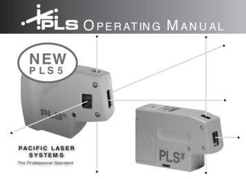
GO TOTable of ContentsPRELIMINARY03-13-200816008 North 81st Street Scottsdale, Arizona 85260 480.483.1214 www.ulsinc.com
Table of ContentsHelp0000 - Contact the ULS Technical Support Department0010 - Performing Professional Series Service ProceduresAdjustments and SettingsA000 - SafetyA005 - Computer Power Management ConfigurationA010 - Laser Power UpgradingA020 - CPU Initialization / Auto-Z and Rotary CalibrationA030 - Cutting Table CalibrationA040 - Rotary CalibrationA050 - X-axis Arm Alignment Check and Adjustment (Squaring)A060 - Laser Beam AlignmentA070 - Z-axis LevelingComponent Removal and ReplacementOpticsR000 - Focusing LensR010 - Mirror 3R020 - Mirror 2R030 - Beam WindowEnclosure and LaserR100 - Rear CoverR110 - Top Door/WindowR120 - Exhaust PlenumR130 - RulersX-AxisR200 - X-Axis BearingsR210 - X-Axis BeltR220 - X-Axis Idler PulleyR230 - X-Axis Motor and Drive GearR240 - X-Axis ArmY-AxisR300 - Y-Axis BeltsR310 - Y-Axis Idler PulleysR320 - Y-Axis Drive GearsR330 - Y-Axis BearingsR340 - Y-Axis MotorZ-AxisR400 - Z-Axis MotorR410 - Z-Axis Board Replacement
ElectronicsR500 - LaserR510 - CPUR520 - KeypadR530 - Upper Flex BoardR540 - Lower Flex BoardR550 - Thermal Sensor BoardR560 - Thermal Snap SwitchR570 - Power Supply(s)PhotosP0010 - Front ViewP0020 - Rear View, Laser Tube InstalledP0030 - Rear View, Laser Tube RemovedP0040 - Left and Right Side Views, PLS3.60, 4.60, 6.60P0050 - Left and Right Side Views, PLS6.120D
Help0000 – ULS Technical Support DepartmentTable of ContentsTechnical Support Department16008 North 81st StreetScottsdale, AZ 85260Phone: 480-609-0297Fax: 480-609-1203Hours: M – F 8 am to 5 pmWeb: http://www.ulsinc.comEmail: support@ulsinc.com
Help0010 – PerformingService ProceduresTable of ContentsSafetyWhen performing the procedures in this manual, always be sure to read and understandthe entire procedure before beginning to operate the machine. Follow each stepcarefully. Pay special attention to steps requiring the PLS to be unplugged!Do not attempt to perform any of the procedures outlined in thismanual until you have read and thoroughly understand sectionA000 – Safety.DifficultyThe PLS is a very easy machine to maintain and repair. Most service procedures aresimple to perform and require minimal time and tools. In order to provide someindication as to the difficulty or involvement of the service procedures in this manual, wehave employed the following system:Procedure requiring very little time and skillProcedure requiring a moderate amount of time or skillA more involved procedure requiring a greater amount of time or skillToolsNearly all the procedures described in this manual can be performed with a minimum ofsimple hand tools:Hex Key Set, Standard (SAE) including sizes:9/64, 1/8, 7/64, 3/32, 5/64, 1/16, .050Screwdrivers, including Phillips #1, #0Lens Cleaning Solution, Cotton Swabs or Lens TissueNeedle Nose Pliers
Adjustments and SettingsA000 – Safety – PLEASE READ!Table of ContentsDescription of Appropriate UseThis device is designed for laser cutting and engraving of the materials listed in the PLSprinter driver. Materials to be processed must fit completely inside the system forproper operation. Use of the equipment in a manner other than that described in thismanual may result in injury to yourself and others and may cause severe damage to theequipment and your facility.General Safety Exposure to the laser beam may cause physical burns and cancause severe eye damage. Proper use and care of this system areessential to safe operation. Never operate the laser system without constant supervisionof the cutting and engraving process. Exposure to the laserbeam may cause ignition of combustible materials and start a fire.A properly maintained fire extinguisher should be kept on hand atall times. Never leave materials in the laser system after laser processinghas finished. Materials may ignite after laser processing hasfinished. Thoroughly inspect the interior of the laser system andremove any particulate materials before leaving your workstation. Aproperly maintained fire extinguisher should be kept on hand at alltimes. A properly configured, installed, maintained, and operating particulate/fumeexhaust system is mandatory when operating the laser system. Fumes andsmoke from the engraving process must be extracted from the laser system andeither filtered through the Integrated Exhaust Filtration Module (an optionalaccessory) or exhausted outside through a user supplied exhaust system. Some materials, during and after laser processing, mayproduce toxic fumes. We suggest that you obtain the MaterialSafety Data Sheet (MSDS) from the materials manufacturer. TheMSDS discloses all of the hazards when handling or processingthat material. Some materials continue emitting fumes for severalminutes after laser processing and may pose a health hazard. Avoid using thisdevice in small, enclosed, or non-ventilated areas. Some materials, during and after laser processing, may producecorrosive fumes. DISCONTINUE processing any material thatproduces signs of chemical deterioration in the laser system such asrust, metal etching or pitting, peeling paint, etc. Damage to the lasersystem from corrosive materials is NOT covered under warranty.
Adjustments and Settings Dangerous voltages are present within the electronics and laserenclosures of this system. Although access to these areas is notnecessary during normal use, if it becomes necessary to open one ofthese enclosures for service reasons, please remember todisconnect the power cord from your electrical supply. Care should be taken when moving or lifting this device.Obtain assistance from 3 or 4 additional people when lifting orcarrying (secure motion system and access door). Severe bodilyinjury may occur if improper lifting techniques are applied or thesystem is dropped.The power supply cord is the mains disconnect device; theequipment should be located close to an easily accessiblewall socket outlet. To disconnect the equipment from the supplymains, the power cord shall be unplugged from the wall outlet ormain power inlet (appliance coupler) of the unit.This device is specifically designed to comply with CDRH performancerequirements under 21 CFR 1040.10 and 1040.11. CDRH is the Center for theDevices of Radiological Health division of the Food and Drug Administration (FDA)in the USA. It also complies with CE (European Community) safety regulations. Noguarantees of suitability or safety are provided for any use other than those specifiedby Universal Laser Systems, Inc.Laser SafetyThe device contains a sealed carbon dioxide (CO2) laser in a Class I enclosure thatproduces intense invisible and visible laser radiation at a wavelength of 10.6 microns inthe infrared spectrum. For your protection, this enclosure is designed to completelycontain the CO2 laser beam.CAUTION – Use of controls or adjustments or performance of procedures otherthan those specified herein may result in hazardous radiation exposure. The intense light that appears during the engraving or cutting process is the productof material combustion or vaporization. DO NOT STARE AT THIS LIGHT FOREXTENDED PERIODS OR ATTEMPT TO VIEW IT WITH OPTICALINSTRUMENTS.This device contains a visible Red Dot Pointer (Class IIIa, 5mw maximum output,630-680 nm). DO NOT STARE AT THIS RED LIGHT FOR EXTENDED PERIODSOR ATTEMPT TO VIEW IT WITH OPTICAL INSTRUMENTS.The user access door of this device is safety interlocked and will disable the CO2laser beam when the access door is opened. The Red Dot Pointer is NOT safetyinterlocked and is activated when the user access door is open.DO NOT OPERATE THE LASER SYSTEM IF ITS SAFETY FEATURES HAVEBEEN MODIFIED, DISABLED OR REMOVED. This may lead to exposure toinvisible and visible CO2 laser radiation which may cause permanent blindnessand/or severe burns to the skin.
Adjustments and SettingsA005 - Computer Power Management ConfigurationTable of ContentsPower management is an option on computers and monitors to reduce energyconsumption when they are not in active use. However, your computer is a criticalcomponent in the operation of the PLS. Active Power Management can causeinterruption of communication between the PC and the PLS, resulting in failure ofoperation.1. With your computer fully booted intoWindows XP, right-click on yourdesktop.2. From the list of options, select“Properties”.The“DisplayProperties” box will open.3. In Display Properties, select theScreen Saver tab. Set the Screensaver to “(None)”.4. Then in the box “Monitor power”,Click the button “Power ”
Adjustments and Settings5. Select the tab “Power Schemes”.6. For the “Settings for Home/OfficeDesk power scheme” box, select“Never” for all the setting options:Turn off monitor, Turn off harddisks, System standby, and Systemhibernates.7. Click “Apply”, then “OK” on bothopen windows.8. The configuration is complete.
Adjustments and SettingsA010 – Laser Power UpgradingTable of ContentsThe PLS3.60, PLS4.60, and PLS6.60 is capable of upgrading to a maximum of 60watts. The PLS6.120D is capable of upgrading to a maximum of 120 watts (two 60 wattlaser tubes).If you are upgrading either system, the PLS’s internal software (firmware) willautomatically reflect the change. Nothing has to be done to the laser system to have itfunction properly.
Adjustments and SettingsA020 - CPU Initialization / Auto-Z CalibrationNOTE: This procedure must be performed with the solid aluminum EngravingTable installed. Do not use the honeycomb Cutting Table for this procedure.Table of Contents1. Power up your computer and the PLS. Home the Z-axis by clicking the HOME Zbutton in the VIEWER tab of the VCP.2. Using the UP and DOWN arrowbuttons, either on the machine (enterthe Z Menu) or in the UCP, bring theZ-axis table up. Using the appropriateFocus Tool for the lens installed (thestandard is 2.0, other Focus Lens Kitsare optional), focus directly on thesurface of the table.3. In the UCP, click the SYSTEM tab and choose 2.0 from the Lens Size list.
Adjustments and Settings4. Click on the Calibrate button within the Lens Size box of the System Tab. Thefollowing window appears. Click on Save to accept the new Z Position. Your 2.0Lens has now been calibrated.5. If you have purchased any other optional lens kits, calibrate the lens kit accordingto steps 1 through 4. Be sure you select the proper lens size from the list beforecalibrating.6. You are now done calibrating your Lens Sizes and the Auto Z feature with thestandard engraving table.
Adjustments and SettingsA030 - Cutting Table CalibrationTable of ContentsInstallation1. Turn the PLS on and lower the table all the way down to the bottom of its travel byusing the keypad or 14151635678910111221222324ADJUSTABLE MANIFOLD12420123456789101112ENGRAVING TABLECUTTING TABLE17181920212223242. Open the front door of the lasersystem and carefully slide the cuttingtable into the laser system so that itsbody is squarely pushed up againstthe engraving table rulers on the topand the side of the table. The rulersof the cutting table should nowoverlap the rulers on the engravingtable.3. After you have installed the Cutting Table into your PLS, manually focus to theCutting Table surface by using the appropriate focus tool.4. Once that is complete, go directly toyour System Tab and you will noticethat the red CALIBRATE button forthe Cutting Table box will beactivated. Click on the CALIBRATEbutton.A window will appear.Accept the new Z-height BY clickingon SAVE.5. You are now done calibrating the new Z-height for engraving or cutting on theCutting Table.
Adjustments and SettingsA040 - Rotary CalibrationTable of Contents1.2.3.4.5.6.7.Turn on the UCP and PLS.Open the top door.Lower the table about half way down by using the UCP or the keypad.Turn off the PLS.Properly mount the Rotary on top of the engraving table and plug it in.Turn on the PLS.The rotary will automatically rotate to indicate it’s properly connected.8. Select the System Tab on the UCPand click on the CALIBRATE button inthe Rotary box. After the button hasbeen clicked a Rotary Calibrationwindow will appear with Y Positionand Z Position boxes. Now, in the YPosition box use the Y Axis buttons(1) to move the focus carriage backand forth. Place the focus carriageexactly at 2.625”.9. Next, use the X Axis buttons (2) to move the focus carriage left and right and placethe red LED over the flat part of the concave metal fixture normally located on theleft hand side on the rotary.
Adjustments and Settings10. Now, use the Z Axis buttons (3) or theZ Axis Menu on your keypad(recommended) to move the table upand down and use the Focus Toolmethod to focus on top of the flat partof the concave metal fixture with thefocus tool. DO NOT focus on top ofthe black metal cover that is locatedon the left hand side of the rotary.11. After focusing is complete click both SAVE buttons on the Rotary Calibrationwindow. If asked to overwrite existing positions accept the new values by clicking onYES. Once complete click the CLOSE button and the focus carriage will re-homeonce you exit the window.12. Calibration is now complete.
Adjustments and SettingsA050 - X-axis Arm Alignment Check and Adjust (Squaring)Table of Contents1. Power off the PLS and unplug it.2. Remove the #2 mirror cover (1) byremoving the thumbscrew (2), slidingthe cover to the right and then off therail.3. Grasp the X-axis arm and slowly pull the arm towards you until it stops.4. Observe if the left side and right side of the X-axis arm makes contact with the leftand right side shoulder screws, at the same time, respectively.5. If there is a gap between the shoulder screw and the contact point on either the leftor right side of the arm, you will need to square the arm by making an adjustment.
Adjustments and SettingsAdjustment6. Locate the Y-axis couplers (1). Foreach of the two couplers, there aretwo screws that mount it to the Ymotor and the Y-axis shaft. Using a3/32 inch Allen wrench, choose ONE(only one) of those four screws (2)and loosen it a ½ turn.7. With your hand, grasp the center of the arm and pull it forward to contact theshoulder screws. While holding the arm against the two shoulder screws, tighten thescrew that you loosened in the previous step.8. Now, push the arm into theapproximate center of the engravingfield. With your thumb and forefingerof your left hand, touch the two y-axisbearings and attempt to “turn” or“rotate” them.10. Re-install the #2 mirror cover.11. Squaring is complete.9. You should feel an equal turningresistance for each bearing. If onebearing spins freely and the other hasa turning resistance, or the turningresistanceisunequal,thenadjustment is necessary. To adjust,using a 3/32 inch Allen wrench,loosen BOTH the two socket headscrews ¼ turn.Then, re-tightenthem. This procedure automaticallyequalizes the force on both Y-axisbearings.Re-check the turningresistance once again and re-adjust ifnecessary.
Adjustments and SettingsA060 - Laser Beam Check and AlignmentTable of ContentsVerify the table is clear of any objects that could obstruct the movementof the motion system. THE RED DIODE IS ONLY A GUIDE. The reddiode may be slightly off center compared to the burn mark you willmake in the following steps so we recommend you make a burn mark forbest results.1. Power the PLS ON and let it home, orre-home it by clicking the Home XYbutton in the Viewer Tab of the UCP.2. Remove the optics from the Focus Lens Carriage by unscrewing all 3 thumbscrews and pull the face plate out towards you. Place the optics in a safe, cleanplace.
Adjustments and Settings3. Place a strip of masking tape over thehole on the left side of the FocusCarriage.4. The red diode beam should appearon the tape. The red diode beamshould be fairly centered over thehole.5. Using the Focus Feature (1) of the Viewer Tab in the UCP, verify the position ofthe red diode beam relative to the hole in the focus carriage in all four corners ofthe table.6. The red diode should be fairly centered on the hole in all four corners of the table. Ifthis is the case, you can remove the masking tape from the hole in the focuscarriage and reinstall the optics. The red diode is aligned.7. If the red diode beam is not centered on the hole in all four corners of the table, thebeam will need to be aligned. Do not remove the masking tape or reinstall the optics.8. Power off the PLS and unplug the unit.
Adjustments and Settings9. Slowly move the X-axis arm (1)forward.10. Locate and carefully remove the largethumb screw securing the cover onthe left-hand side of the X-axis arm.Remove this cover.11. Plug in the PLS and turn the power on with the top door open.12. Once it finishes homing proceed to the System Tab then click on the AlignmentLaunch button. The Alignment Mode window will appear.13. Click on the upper left hand Movebutton. The PLS’s focus carriage willmove to the indicated X, Y position.14. With the cover removed, locate the three adjusting screws on the #2 Mirror mounton the left-hand side of the X-axis arm. Turn these screws to center the red dotdiode.
Adjustments and SettingsNote: To create a small burn mark on the tape in the next step you will need to adjustyour Power and Seconds settings in the Alignment Mode screen (lower left side).Lower power laser tubes require higher power settings and higher power laser tubesrequire lower power settings to make the burn mark on the tape.15. Once the red diode is centered adjustthe Power and Seconds settings onthe lower left side of the AlignmentMode window.Start of with 5%Power and 2 Seconds.16. Close the top door if it’s not alreadyclosed and then click on the ActivateLaser button. If a burn mark is not madecontinue to modify the Power andSeconds settings.17. If the burn mark is not centered use a new piece of tape and adjust thecorresponding screw in small turns on the #2 Mirror mount until the burn mark iscentered. Keep in mind that you can use the red diode as a guide.18. If the burn mark is centered continue to the next step.19. Once the burn mark is centered keep the piece of tape on the focus carriage.20. Now click on the lower right sideMove button.21. Close the top door if it’s not alreadyclosed and then click on the ActivateLaser button. Take note of the burnmark.22. Both burn marks should be over lapping each other. If they are not continue toadjust the #2 Mirror for the lower right hand corner.23. Once aligned Exit the Alignment Mode Window and remove the masking tape fromthe Focus Lens Carriage and reinstall the optics.24. Power off and unplug the PLS.25. Reinstall the cover and two screws over the #2 mirror mount from step 10.
Component Removal and ReplacementR000 – Focusing LensTable of Contents1. Make sure the PLS is powered OFF and unplugged.2. Open the top door and pull the X-AxisArm (1) forward.3. Locate the Focus Carriage (1).4. Remove the three thumbscrewscompletely (2). Set them aside in asafe place.5. Grasp the Front Cover Plate (3).Gently slide it forward and out of theFocus Carriage to remove the optics.6. Place the optics on a soft, non-abrasive cloth.7. Remove the two Phillips head screws(1) that attach the Focusing Lens tothe Front Cover Plate and remove theoptic.8. Attach the new Focus Lens to theFront Cover Plate.9. Clean the #3 Mirror (2) if necessary.10. Reinstall the optics in the Focus Carriage.
Component Removal and ReplacementR010 – #3 MirrorTable of Contents1. Make sure the PLS is powered OFF and unplugged.2. Open the top door and pull the X-AxisArm (1) forward.3. Locate the Focus Carriage (1).4. Remove the three thumbscrewscompletely (2). Set them aside in asafe place.5. Grasp the Front Cover Plate (3).Gently slide it forward and out of theFocus Carriage to remove the optics.6. Place the optics on a soft, non-abrasive cloth.7. Remove the two Phillips head screws(1) that attach the #3 Mirror to theFront Cover Plate and remove theoptic.8. Attach the new #3 Mirror to the FrontCover Plate.9. Clean the Focus Lens (2) ifnecessary.10. Reinstall the optics in the Focus Carriage.
Component Removal and ReplacementR020 - #2 MirrorTable of ContentsNote: Be careful not to touch the #2 Mirror.1. Make sure the VLS is powered OFF and unplugged.2. Open the top door and slowly slidethe X-Axis Arm (1) forward.3. Locate and carefully remove the largethumb screw securing the cover onthe left-hand side of the X-axis arm.Once the thumbscrew is removedslide the cover to the right and up andset it aside.4. Grab a hold of the Bezel MirrorHolder and turn it counter clockwiseto remove it. Place it in a safe place.5. Replace the #2 Mirror with the newmirror by verifying that the reflectionside is facing inside the lasermachine. Installing the mirrorbackwards within the bezel willdestroy the mirror once the laserbeam penetrates the backside ofthe mirror, so be sure that you reinstall the mirror correctly.
Component Removal and ReplacementR100 - Rear CoverTable of Contents1. Power off the PLS.2. Walk around to the back of the laser machine.3. Open the rear cover by pressing downon the button part of the latches untilthe latches pop up.4. Fold the rear cover down to a resting position.
Component Removal and ReplacementR110 - Top Door/WindowTable of ContentsObtain assistance from 1 or 2 additional people when removingthe top door.1. Make sure the PLS is powered OFF and unplugged.2. Open the top door and locate the 2hydraulic pressure cylinders. Placea flat head screw driver between theslots and push inward to unlock thecylinders. Do not remove the endcaps.3. Next, place the flat head screw driveragainst the frame of the top door andthe hydraulic pressure cylinder andpush inwards.The hydraulicpressure cylinders will come off.4. Have another person hold the top door and unscrew the 4 screws that hold the topdoor in place. Place the screws and washers in a safe place.5. Place the PLS’s top door on a soft flat sturdy surface like a table with a cloth.
Component Removal and Replacement6. Locate the 12 window nuts and remove them with needle nose pliers like shown.Set the window nuts aside.7. With the top door still on a flatsurface carefully remove all fourGlass Window Mounts by gentlyprying them with your fingers. TheGlass Window Mounts may stick onthe top door window.8. Install the new glass window onto the top door frame.9. Installation of the Top Door is opposite of removal.10. Plug in and power ON the PLS. Open and close the door. Check to see if the RedDiode turns on and off when you open and close the top door, respectively.
Component Removal and ReplacementR130 – RulersTable of Contents1. To replace the rulers you need toremove all 5 screws and set themaside.2. Once the rulers are removed, use some solvent cleaner to remove and debri leftover from the removed rulers.3. Place masking tape on the table over the approximate location of the ruler positionsextending the full length of the table in box axes.4. Using your graphic software, create a red line box that outlines the page sizeperfectly.5. Run that cut file to see the exact location of where the edges of your rulers shouldbe.6. After the cut file has been run, peel the outside masking layer off leaving the insideportion to set your rulers to.7. Gently push the rulers against the leftover masking tape.8. Once the rulers are in the correct place, reuse the screws from step 1 and securethem to the engraving table.9. Remove the masking tape from the inside.
Component Removal and ReplacementR200 - X-axis BearingsTable of Contents1. Power OFF and unplug the PLS.2. Open the top door and bring the XAxis Arm (1) forward.3. Bring the Focus Carriage to the middle of the X-Axis Arm.4. Remove the 2 screws located to theright of the Focus Carriage on the beltclamp. Be careful not to lose thewashers.5. If you have Air Assist, unscrew the two screws that hold the Hook Manifold inplace and set the screws aside. Do not pull the Air Assist hoses out of the AirAssist Track.
Component Removal and Replacement6. Grab a hold of the Focus Carriage and gently push up then tilt forward to removethe Focus Carriage from the X-Axis Arm.7. Hold the Focus Carriage with yourhand or place it on a flat surface andremove all 3 bearings.9. Installation is opposite of removal.8. Take notice of the Bearing Assembly.There is a small wave washer (2)between the head of the axle (3) andthe bearing (1). Be careful not lose ordamage this washer. The bearingitself has no orientation and can beinstalled with either surface againstthe carriage.
Component Removal and ReplacementR210 - X-axis BeltTable of Contents1. Power OFF and unplug the PLS.2. Remove #2 mirror cover by removingthe thumbscrew and sliding the coverto the right and up.3. Remove the two screws (upper andlower) that attach the Belt Clamp tothe Focus Carriage. Slide the FocusCarriage off to the left.4. Loosen the three screws (3) (1/2 turn)that mount the tensioning bracket (2).Also, back off the setscrew (1) untilthe tip does not make contact (thiswill partially release the tension onthe belt) but do not remove the screwcompletely.5. Loosen, do not remove, the 2 screwsthat attach to the left of the bracketthat holds the ends of the belttogether. Slide the bracket off of theend of the belt. DO NOT PULL THEBELT OUT OF THE X-AXIS RAIL ATTHIS TIME.JUST LEAVE ITHANGING. THE PURPOSE IS TORELEASE THE BELT TENSIONCOMPLETELY.
Component Removal and Replacement6. Using a stapler, attach one end of theold belt (2) to one end of the new belt1). Do not overlap the belt and makesure that the teeth are in the samedirection.7. Slowly pull the other end of the oldbelt, allowing the new belt to bepulled through the inside of the X-axisarm. Make sure that you do not twistthe belt going through the rail. Theteeth of the belt should be facing theinside.8. Once the new belt is completely through the X-axis rail, remove the staple anddiscard the old belt.9. Re-attach the belt clamp to the ends of the belt. Make sure that the rounded sideof the clamp faces inwards. Gently pull the belt through the clamp until the slackin the belt is reduced. Leave the belt slightly loose because we will tension thebelt by adjusting the setscrew on the tensioner bracket on the left side of the Xaxis rail. Now, tighten down the screws on the clamp. DO NOT TRIM OFF THEEXCESS BELT AT THIS TIME, WE WILL DO THAT LATER.10. For the next step, you will need a spring scale and a ruler which the end of the ruleris actually the "0" point. Some rulers "0" point is offset from the end so you wouldnot want to use that kind of ruler.
Component Removal and Replacement11. Push the focus carriage all the way tothe left and push the belt clamp allthe way to the right, on the X-axis rail.Place the end of the ruler up againstthe middle of the X-axis arm (NOTinside the belt groove). Hook thespring scale onto the middle of thebelt and pull the scale until you reach1/2 inch. You should read 100 - 125grams (PLS6.60 and PLS6.120D) or150 - 175 grams (PLS3.60 andPLS4.60). We are expecting you tobe loose at this point so you willprobably read less than what isrequired.12. Using scissors trim off the excess beltmaterial but leave at least 1/4 inch ofbelt protruding out of the belt clamp.DO NOT trim the belt flush with theclamp.Although this may lookcleaner, trimming it flush willeventually cause the belt to slip out ofthe clamp and would require thereplacement of the entire belt (refer tophoto above).13. To tighten the belt, slowly tighten thesetscrew (1) on the tensioningbracket (2) that was loosened earlierand keep re-checking the scale untilyou have the proper tension. Afterproper tension is achieved, tightendown the three tensioning bracketmounting screws (3) and re-check thetension to make sure that it has notchanged.14. Re-attach the belt clamp to the side of the Focus Carriage.15. Re-install the #2 Mirror Cover and thumbscrew.16. X-axis belt replacement is now complete.
Component Removal and ReplacementR220 - X-Axis Idler PulleyTable of Contents1. Power OFF and unplug the PLS.2. Remove #2 mirror cover by removingthe thumbscrew and sliding the coverto the right and up.3. Loosen the three screws (3) (1/2 turn)that mount the tensioning bracket (2).Also, back off the setscrew (1) untilthe tip does not make contact (thiswill partially release the tension onthe belt) but do not remove the screwcompletely.4. Once the tension has been released 5. When reinstalling the new Idler Pulleyremove the screws on the Idler Pulley.insert the pulley in at an angle forRemove the pulley and replace it witheasier access.a new one.6. Retention the X-Axis Belt.7. Replace the #2 Mirror Cover and screws.
Component Removal and ReplacementR230 - X-Axis Motor and Drive GearTable of Contents1. Power Off and unplug the PLS.1. Remove #2 mirror cover by removingthe thumbscrew and sliding the coverto the right and up.2. Loosen the three screws (3) (1/2 turn)that mount the tensioning bracket (2).Also, back off the setscrew (1) untilthe tip does not make contact (thiswill partially release the tension onthe belt) but do not remove the screwcompletely.2. Once the tension is released from theX-Axis belt, detach the flexible cable(1) from the X-axis motor housing bypressing your fingertip on theunderside of the cable, depress thelocking tab (2), and gently pull thecable out.3. Be careful not to make contact withthe Y-axis Home Sensor (3), it ismade out of plastic and can easilybreak. Remove the mounting screw(4) with a 3/32 Allen wrench. It is atight fit under there and is very darkso you may need to use a flashlight tosee it.
Component Removal and Replacement4. Remove the other mounting screw (5) is on the front side of the motor housingwith a 3/32 Allen wrench. Lift the motor housing off of the arm and put it on atable in a safe place. Be careful not to drop the Motor Module or touch the Y-axi
by Universal Laser Systems, Inc. Laser Safety . The device contains a sealed carbon dioxide (CO2) laser in a Class I enclosure that produces intense invisible and visible laser radiation at a wavelength of 10.6 microns in the infrared spectrum. For your protection, this enclosure is designed to completely contain the CO2 laser beam.