Transcription
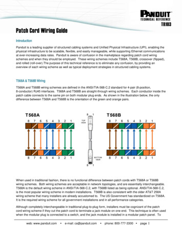
wwWiringDiagramsintroductionThis booklet has been prepared as a guide tosome of the useful ways Allen-Bradley’smanual and magneticacross-the-linestartersmay be applied. It will also serve as a usefulaid where simple wiring systems are to bestudied.When applying these diagrams, it is well torememberthat the featuresdescribedinseveral diagrams may be combined into oneto produce another useful way of applyingAllen-Bradleyequipment.As you becomefamiliar with the diagrams, most such changeswill prove simple.be extremelyunderstandingExercisesof this kind willbeneficial to a student’s betterof motor control wiring dia-grams. It is important to note: A particularapplicationmust satisfy the needs of the userand comply with applicable codes, laws andstandardsbefore using any of the typicalcircuits shown in this publication.Thesymbolsusedin thisbookletwereadoptedby Allen-Bradleyfor use in all itspublications.They are in accordancewithNEMA standards.The Allen-BradleyCompanyis veryinter-ested in helping engineers, electriciansandstudents to a better understandingof motorcontrolequipment.bookletfurthersIt is our hope that thisthis purpose.
WIRING DIAGRAMSwnvc o n t e n t sPLATEPAGEIntroduction . . . . . . . . . . . . . . . . . . . . . . . . . . . . . . . . . . . . . . . . . . . . .2Wiring Diagram Symbols . . . . . . . . . . . . . . . . . . . . . . . . . . . . . . . . .4Common and Important Terms. . . . . . . . . . . . . . . . . . . . . . . , . . . .6Bulletin 600 Manual Single Phase Starters . . . . . . . . . . . . . . . . .1 thru 47Bulletin 609 Manual Starters . . . . . . . . . . . . . . . . . . . . . . . . . . . . . .5 thru 138Bulletin 509 Magnetic Full Voltage Starters . . . . . . . . . . . . . . . .Three-Phase Starters . . . . . . . . . . . . . . . . . . . . . . . . .Single-Phase Using 3-Phase Starter . . . . . . . . . . .Variations With START-STOP Stations . . . . . . . .Step-Down Transformer in Controls Circuits . . .Jogging . . . . . . . . . . . . . . . . . . . . . . . . . . . . . . . . . . . . .Two-Wire Control Circuits . . . . . . . . . . . . . . . . . . . .Pump Operation (Backspin and Surge Protection)Sequence Control . . . . . . . . . . . . . . . . . . . . . . . . . . . .14 thru 1718 and 1920 thru 242526 and 2728 thru 3233 and 3435 thru 37111214151819202324Bulletin 505 Magnetic Reversing Starter . . . . . . . . . . . . . . . . . . . .Three-Phase Starters. . . . . . . . . . . . . . . . . . . . . . . . . .Push Button Variations . . . . . . . . . . . . . . . . . . . . . . . .Jogging . . . . . . . . . . . . . . . . . . . . . . . . . . . . . . . . . . . . . .Plugging . . . . . . . . . . . . . . . . . . . . . . . . . . . . . . . . . . . . .Anti-plugging . . . . . . . . . . . . . . . . . . . . . . . . . . . . . . . .38 and 3940 thru 444546 and 4748262728313234Bulletin 520 Multi-Speed Motor Starters . . . . . . . . . . . . . . . . . . . .49 thru 51353
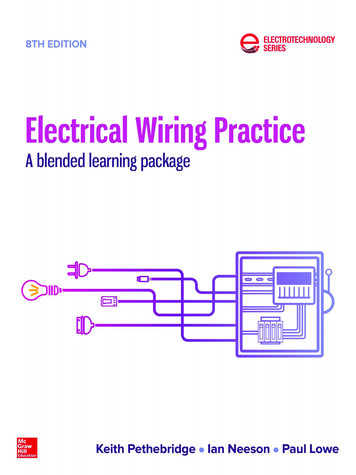
Key to SymbolsShown here are the symbols most often used in this book. Althoughthe explanationsaccompanyingthe diagramsdescribe the devices used, familiaritywith the varioussymbols will lead to a quicker understandingof each circuit.The symbols,device designations,and abbreviationsStandard Publication/No.in this book are taken from the NEMAICS-1-1978.Wiring Diagram n E -OranoeAmb&BlueClearGreenRedWhiteYellow3 PhaseSquirrelAuxiliaryCageInductionTN.O.T.C.P - Purple- OpalescentGeneral#S# i?(N.C.)Normally-FL - FluorescentCoilsMotorsN.C.T.C.SingleTimeOpening- tifierContactorsFull WavewithColor Code- r IRedBlkManuallyOperatedACYelYel
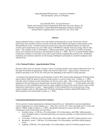
WIRINGDIAGRAMSSymbolDeviseSyfnbolH-q -m cwPlugging(P4Of.t Shown)Opening OnRising Press.Closing OnRising Press.PressureTandTemperatureTTTOpening OnRising Temp.Closing OnRising Temp.ThermalOverloadPush ButtonStandardL0LLLQ0NONCRelaysPush ButtonIiL0rLl300Heavy Duty,Oiltight0MushroomHeadSwitcheswTiming’Push ButtonInst. Jog0 0and JogAttachmentOn Delay‘3p T.C.9T.O.StandardJoDutySelectorJo3 Position2 ector1s HeldOpenCurrent2PolarityMark
mwcWIRINGDIAGRAMSSOME COMMONand IMPORTANTTERMSIn this booklet, and wherever motor control is discussed, there are several terms which are used repeatedlybut whosemeanings are often not completelyunderstoodby the reader. These terms represent things which are actually quitesimple and everyoneshould become familiar with them as standard“motor control jargon.”UNDERVOLTAGERELEASEAlso Called: Low-Voltage ReleaseTwo-Wire ControlUNDERVOLTAGEPROTECTIONAlso Called: Low-Voltage ProtectionThree-Wire ControlThese terms mean that the starter will drop out whenthere is a voltage failure and will pick up again as soonas voltage returns. Reference to the diagram below willshow how this occurs. The pilot device is unaffectedbythe loss of voltage and its contact remains closed, readyto carry currentas soon as line voltagereturnstonormal.These terms mean that the starter will drop out whenthere is a voltage failure but will not pick up automaticallywhenvoltagereturns.The controlcircuitiscompletedthroughthe STOP button and also througha “holding”contact(2-3) on the starter.When thestarterdrops out, this contactopens,breakingthecontrol circuit until the START button is pressed onceagain.L3%T3 tThreeTwo wres lead from the plot devrce to the starter. “Undervoltage release”and“two-wwecontrol”should brrng to mrnd an automatrc p/lot devrce such as alrmrt swrtch or float switch whose functron IS openmg and closrng the controlcrrcurt by means of a smgle contact.WiresThree wjfes lead from the p/lot devtce to thestarter.“Undervoltageprotection”and “three-wrre”control should brmg to mrnd a START-STOPpush buttonstat/on whrch IS the most common means of provrdrng this type of control.The main distinctionbetweenthe above two types of controlis that with undervoltage release the coil circuit ismaintainedthroughthe pilot switch contact,and with undervoltage protection it is maintainedthrougha “stop”contacton the push button station and also an auxiliarycontact on the starter. The designations“two-wire”and“three-wire”are used only because they describethe simplest applicationsof the two types. Actually,in othersystems, there might be more wires leading from pilot device to starter but the principle of “two-wire”or “three-wire”control would still be present.“WIRING DIAGRAMS”Most of the diagramsin this book are shown in twoways. There is a “wiring diagram”and adjacent to it a“line diagram.”Line diagramsare includedbecausetheir use is becomingmore widespreadand we believeit is advantageousto learn to use them.Wiring diagrams or connectiondiagramsinclude allof the devices in the system and show their physicalrelationto each other. All poles, terminals,coils, etc.are shown in their proper place on each device. Thesediagramsare helpfulin wiring-upsystems,becauseconnectionscan be made exactly as they are shown onthe diagram. In followingthe electrical sequence of anycircuit, however, the wiring diagram does not show theconnectionsin a manner that can be easily followed.For this reason a rearrangementof the circuit elementsto form a line diagram is desirable.The line diagram (sometimesreferredto as anelementary diagram or a schematic diagram) is arepresentation6of the systemshowingit in the simplestvs “LINE DIAGRAMS”way. No attempt is made to show the various devices intheir actual relative positions.All controldevices areshownbetweenverticallines whichrepresentthesourceof controlpower,and circuitsare shownconnectedas directlyas possiblefrom one of theselines to the other. All connectionsare made in such away that the functioningof the various devices can beeasily traced. Note: In this publicationthe line diagramsshow the controlcircuitsonly - power circuitsareomitted for clarity, since they can be traced readily onthe wiring diagrams(heavy lines).A wiring diagram gives the necessary informationforactuallywiring-upa group of controldevices or essary.A line diagram gives the necessary information for easily followingthe operationof the variousdevicesin the circuit.It is a great aid in troubleshootingas it shows, in a simple way, the effect thatopeningor closingvariouscontactshas on otherdevices in the circuit.
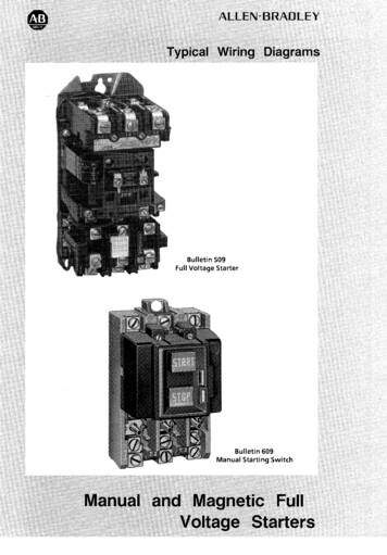
WIRINGDIAGRAMSm cw600BulletinBulletin 600 manual starting switches are designed for starting andprotecting small AC and DC motors rated at 1 HP or less whereundervoltage protection is not needed. They are operated by a togglelever mounted on the front of the switch. Wiring diagrams do not show theoperating mechanism since it is not electrically controlled.These motor starters consist of an “ON-OFF” snap switch combined witha thermal overload device operating on the eutectic alloy ratchet principle.Terminal markings corresponding to those shown on the diagrams will befound on each switch.--7L2I:--.%. i)Catalog No. 600-TAX4liSingle pole switchescan be used wherevertheelectricalrequirementspermit only one motorline to be broken.1*;;F LrFI,.“rc-l.L. ’.*Catalog No. 600-TAX109Double pole switch with built-into indicate when switch is on.NeonpilotlightSingle Phase Lines.L2 .LlClosing“r-”Rising Temp.Tl.?iI : .G“.1 , “r r.i-&rCatalog No. 600-TAX9Catalog No. 600-TAX293For use with automaticpilot devicessuch asthermostats,and float switches. A selector switchis mountedin the same enclosureto allowmanual operationof the automaticallycontrolledequipment.Two speed manual motor starter is designedforstarting and protectingsmall, single phase, twospeed AC fan motors.*.I3c-se;- .- *-'-E irnr .
WIRINGDIAGRAMSBulletin 609 manual starters are operated by “START-STOP” pushbuttons mounted on the front of the starter. They are used inapplications which do not require undervoltage protection. Wiringdiagrams do not show the operating mechanism since it is notelectrically controlled. Pushing the “START” button mechanicallycloses the contacts, connecting the motor to the line. The contactsare opened by pressing the “STOP” button. Terminal markingscorresponding to those shown on the diagrams will be found oneach switch.--Tli;Sizes 0 and 1Sizes 0 & 13 Phase(For 2 Phase,or 2 Phase,Direct3 WireCurrent3 Wire, L2 and T2 are common)6Sgl. Phase LinesPilotLightRedBlackSizes 0,lSingle8and 1PPhaseSizes 0 & 13 PhaseWith PilotLight
WIRINGBulletinDIAGRAMS609RSw& 609TSThe Bulletin 609RS manual reversing starters and theBulletin 609TS manual two-speed starters consist oftwo standard Bulletin 609 starters mounted in a singleenclosure. Internal wiring of these starters provides thenecessary connections for interchanging two motorconnections in the case of the 609RS or switching toanother winding in the case of the 609TS. Bulletin609TS is for two-speed separate winding motors only.Terminal markings corresponding to those shown onthe diagrams will be found on each switch.ReversingStarterBulletin609RSSizes 0 & 13 Phase2 Phase, 3 WireTwo-SpeedStarterBulletin609TSSizes 0 & 13 Phase2 Phase, 3 WireTlTlTll(For separatewindingmotorsonly)
WIRINGwBulletinDIAGRAMS609UThe Bulletins609U and 609TU are the same as the standardBulletin609 Manual Starters except for the additionof UnderThese startersprovidefull line voltagevoltageProtection.starting,reliable thermal overloadprotection,as well as UndervoltageProtection.Typicalapplicationsare on woodworkingmachinery,metal sawing machines,and many other machinetools where UndervoltageProtectionis needed to meet safetystandards.Sizes 0, 1 and 1P?1Pilot Light2 - v.b-71-r-i,1d13 PhaseRemove jumper “A” to connectremote emergencystop operator wiresto vacatedterminals.Note: The remote stop terminalblock and jumpers are not availableon devices inNEMA Type 7 and 9 enclosures.Sizes 0, 1 and 1PSingle-- LUndervoltageCoilPilot LightIL --------------------/’BlackLT2/PhaseRemove jumper“A” to connectremote emergencystop operator wiresto vacated terminals.Note: The remote stop terminalblock and jumpers are not availableon devicesinNEMA Type 7 and 9 enclosures.12Sizes 0, 1 and 1P3 Phase With 120 Volt SeparateCoilThesestartersmustbe properlyapplied with a remote control transformer to provide undervoltageprotection.Connecttransformerprimary to the line side of the starterand the 120 volt secondaryto theundervoltagecoil as shownin thediagram.10
WIRINGDIAGRAMSBulletinw509THE BULLETIN 509 AS REPRESENTED BY A WIRING DIAGRAMCoilIBulletin 509 Starter, Size 1Wiring Diagram ForBulletin 509 Starter, Size 1Comparisonof the picture and drawing shown above should help the reader becomefamiliar with the Allen-BradleyBulletin 509 starter as it is representedin wiring diagramform. Principal correspondingparts are labeled so that the wiring diagram can be comparedwith the actual starter. This should aid in visualizingthe starter when studying a wiringdiagram and will help in making connectionswhen it is actually wired up. Note that thewiring diagram shows as many parts as possible in their proper relative positions. It is notnecessary to show the armature and crossbar or the overload reset mechanism in the wiringdiagram since these parts need not be consideredfrom the wiring standpoint.The Size 1 starter is shown here because all of the special wiring diagrams in this booklet useSize 1 starters as examples. The other sizes of starters have a similar appearance as the Size1 and their principle of operation is the same. Wiring of the other sizes of starters is the sameas for Size I although some of the connectionsare not physically located in the same placesas on the Size 1.
m6 WIRINGwBulletin509DIAGRAMS3-Phase StartersT3Bulletin 509Sizes 0, 1, 2, 3 814Bulletin 509Size 00Standardwiring with STARTSTOP push button stationStandardwiring with STARTSTOP push button station3-Phase LinesdIIBulletin 509Size 5Standardwiring with START-STOPpush buttonstation.Currentformers are utilized thereby allowingthe use of Size 1 overloadtransrelays.16
WIRINGDIAGRAMSw509Bulletin3 Phase “(A2Xj’II251AStartI2236%’ ’ (AIX)5,(A3X)’ ‘(A3Y)-1 Econ.Cap.Bulletin 509 Sizes 7 and .YIlh4,)
wBulletinWIRINGDIAGRAMS509Single Phase Using Standard S-Phase StartersSizes 0, 1, 2, 3, & 4Standardwiring with STARTSTOP push button station.115 Volt Motor230 Volt Motor18Variations with START-STOP StationsMore Than One START-STOP StationUsed to Control a Single StarterThis is a useful arrangementwhen amotor must be started and stopped fromany of several widely separated locations.Notice that it would also be possible touse only one “START-STOP”station andhave several “STOP” buttons at differentlocationsto serve as emergencystops.Standardduty “START-STOP”stationsare providedwith the connections“A”shownin the adjacentdiagram.Thisconnectionmust be removed from all butone of the “START-STOP”stations used.Heavydutyand oiltightpush buttonstations can also be used but they do nothave the wiring connection“A”, so it mustbe added to one of the stations.
WIRINGDIAGRAMSBulletinVariations With START-STOP Stationsm 5w509,. .I.START-STOP Station with Pilot Lightto Indicate When Starter is Energized.A pilot light is to be used with a three-wire“START-STOP”station, so that it will beon when the starter is energized.The light is shownhere as separatelymounted,but it can be combinedin thesame enclosurewith the start and stopbuttons. Stations combiningall three are:CatalogNumberStandardDuty120 or 24O.V800S-2SAPHeavy Duty120 V240 V480 V, 60 Hz600 V, 60 Hz800H-2HAR800H-2HAP800H-2HAY800H-2HAVOiltight120 v240 V480 V600 V800T-2TAR800T-2TAP800T-2TAY800T-2TAV20Pilot LightStation with Pilot Light to IndicateWhen Starter is Deenergized.If it is necessaryfor a pilot light to showwhen the starteris de-energized,thisrequirementis most easily fulfilledbyattachinga normallyclosed Bulletin 595auxiliary contact to the starter and connectingit betweenLl and L2 in serieswith the pilot light. “A” representstheBulletin 595 auxiliarycontact which canbe added to any Allen-BradleyBulletin500 Line starter, sizes 0 through4.If the pilot light is to be includedin thesame enclosurewith the start and stopbuttons,any of the push button stationslisted with drawingNo. 20 can be used.The Bulletin595 auxiliarycontacthasmany other uses besides the ones shownhere. It can also be used to operate othercontrol circuit devices, interlock starters,etc.
wBulletinWIRINGDIAGRAMS509Variations With START-STOP Stations--.,, j ”Is,,\. *,Startr-7I-- III1Three Starters are Operated from a Single “START-STOP” Station. An Overload on AnyOne of the Motors will Drop Out All Three StartersThree Bulletin 509 solenoid type starters are to be connectedso that all are controlledfrom asingle “START-STOP”push button station. A maintainedoverloadon any motor, trippingout the overloadrelays on its respectivestarter, will drop out all three starters disconnectingall motors from the line.Assumingthat standardBulletin 509, Form 2 starters are to be used, then in order to obtainthe desired operation,the wiring connection“Y” must be removed from each starter. Thecontrolcircuitsof the several startersare interconnected.It is thereforenecessarytodisconnectthe power to the line terminalsof all the startersin order to completelydisconnectthe equipmentfrom line voltage.16
WIRINGDIAGRAMSVariations With START-STOP Stations- . .-*.T”“ TddT36!r-%TdT26yT36otor JT26L(.otorT36vEach Starter is Operated by Its Own “START-STOP” Station. Overload on One DropsOut All Starters. A Master “STOP” Station Can Be ProvidedSeveral starters (3 used in diagram)are to be wired so that each starter is operated from itsown “START-STOP”push button station. However, a maintainedoverload, tripping a relayon any one of the starters, will automaticallydrop out all of the starters. A master “STOP”station wired into the circuit as illustratedwill trip out all starters when pushed.To obtain the desired operationusing standard Bulletin 509 Form 2starters, wire“X”must beremovedfrom all but one of the starters. The controlcircuits of the several starters areinterconnected.It is thereforenecessaryto disconnectthe power to the terminals of all thestarters in order to completelydisconnectthe equipmentfrom line voltage.
* .1 . i - I.cI’.- ”apxLlllrwssYi-a’ StationsTwo Starters are to Be Operated from a Single Station,But a Short Delay Must Prevent Them from Being Energized TogetherIn some cases, the power distributionsystem does not havesufficientcapacity to start several motors simultaneously.Ifseveral motors are to be startedfrom the same push buttonstation under these conditionsa time delay can be providedbetweenthe operationof themotor starters.When the STARTbuttonispushed, the first starter is energizedalong with a timingrelay. When the timingrelaytimes out, it operates a contactwhich closes the controlcircuit of the second starter. (Thetimer can be a Bulletin 849.)-7TN.0.T.CYYMotor1If more than two starters are tobe used, additionaltimers willhave to be added in the sameway as the one shown connected to Ml here.24Step-Down Transformer Provides Low Voltage for ControlCircuit Wired for Three-WireControlThe starter coil is to be operated on a voltagelower thanline voltage. (Usually done forsafety reasons.) This requiresthe use of a stepdowntransformer in the pilot circuit. Thestarteris operatedfroma“START-STOP”push buttonstation,either Bulletin8OOS800H or 800T.When a controlcircuitstepdown transformeris used witha standard Bulletin 509 starter,the wiring connection“X” mustbe removed. Note that a fuse isadded to the transformersecondary.18T3 *Motorb1
WIRINGDIAGRAMSJogging-3Separate “START-STOP-JOG” withStandard Push Buttons and a JOG RelayThe Bulletin 509 starter is to be operated by a“START-JOG-STOP”push button station.The purpose of joggingis to have the motoroperate only as long as the “JOG” button isheld down. The startermust not “lockin”during jogging,and for this reason the “jogrelay” is used.StartJogT3:stopI’stop 1 Jog &CRm-Relayn,Pushing the “START”button operates the jogrelay, causingthe starter to lock in throughone of the relay contacts.When the “JOG”button is pressed, the starter operates, but thistime the relay is not energizedand thus thestarter will not lock in.CR representstheNumber 700-C200.“jogrelay,”a CatalogFor a surface mountedheavy duty “STARTJOG-STOP”station, specify Catalog Number800H-3HG.A Catalog Number 800T-3TG canalso be used.Combined “START, JOG” and Separate“STOP” With Selector SwitchJogging With a Selector SwitchtHere, a three-unitpush button station with aSTART-STOPand selectorswitchis used.Heavy duty station is Catalog Number 800H3HW14 and oiltight Catalog Number is 800T3TW15.The circuitto the hold-incontact“M” isbrokenwhen the selectoris in the “JOG”position.The “START”buttonis used to“JOG” or “RUN” the motor, dependingon theposition of the selector switch.
Q3CWIRINGBxtinDIAGRAMS509Two-Wire Control CircuitsStarter Operated by Pressure Switch or Thermostat with Manual Control Provided by aSelector Switch. High Pressure Cut-OutSwitch Can be AddedThe selector switchpart of the starter.featurecan be obtainedasThe selectorswitchmakes it possibletooperate the starter manuallyfor testing or incase of failure of the automaticpilot control.When a standardBulletin 509 across-the-linestarter withoutpush buttons is used, connection “Y” is removed and the wiring follows thesolid lines of the diagram.If a “high pressure” cut-out switch is added, itshould be inserted in the line leading from Llto the “HAND”terminal of the selectorswitch.“A” representsthe thermostator “lowsure” switchand “B” representsthepressure”cut-outor “safety”switch.pres“highFor the “HAND-OFF-AUTO”selector switch,either a Catalog Number 800T-R3SX(standard duty),a CatalogNumber800H-R3HA(heavyduty),or a CatalogNumber800TR3TA (oiltight)can be used.Two-Wire Control with Control Relay Addedto Provide Under Voltage ProtectionUndervoltageprotectionis often necessarywhen two-wirecontrolis used in a locationwhere line disturbancesare frequent.Sincethe two-wirepilot device is not affectedbyloss of voltage, its contact will remain closedeven though there is no power on the line. Thismeans that withoutthe featureof sethe starterto “chatter”andweldingof contactsmight result.Undervoltageprotectioncan beimprovesafety,where automaticafter a power outage is hazardous.Reset- I2-q-0%---CRaddedtorestartingIf a voltage failure relay is added, it will openthe pilot circuit at a bad voltage dip or poweroutage and will not permit the starter to closeagain until the relay has been reset.“A”representsthe two-wirepilotdevice.The reset button,can be a Catalog800H-1 HG (heavy duty) or a Catalog800T-1 TG (oiltight).NumberNumberLlReset1-LL7CR representsthe voltagefailurerelay. ACatalog Number 700-C200 relay can be used.Device20
WIRINGDIAGRAMSBulletinmmnv509Two-Wire Control CircuitsStarter is Controlled by a Gauge-TypeThermostatSince the contacts of a thermostatof this typeusually cannot handle the current to a startercoil, a “thermostatrelay” must be used as anintermediatestep betweenthermostatandstarter.The relayis energizedwhenthe“CLOSE”contactis made and de-energizedwhenthe “OPEN”contactis made. The“OPEN”contactby-passesthe relay coil tode-energizeit. A resistor, built into the relay,guardsagainsta short circuitwhen this isdone.IIIThe thermostatcontactsmustbe adjustedtoo close to onethis may burn out the resistanceadvisableto check the inrushrelay against the current ratingstat. This schemecan alsopressure controls.I1 Close “A” OpenI7“A” representsthe three-wiretemperaturecontrol device.Res.not overlap oranother,sinceunit. It is alsocurrentof theof the thermobe used withgaugetypeCR represents the thermostatrelay. A CatalogNumber 700-BA200can be used here.L3fOpenI“A” Closel-bIStarter is Controlled by a Gauge-Type Thermostat Whose Contacts Can Switch Only aSmall Amount of CurrentHere is another method of protectingthermostat contacts from high current. This scheme,however,is for use with a thermostatwhosecontacts can handle even less current than theones in the previousexample.In a case like this, it is advisableto use relayshavingcoils which operateat a very smallvalue of volt-amperes.This will reduce theburdenon the thermostatcontactsand isespeciallyadvisable where frequent operationis required.“A” representsthe three-wiresensitive gauge type control.CR1 and CR2 representlow coil currentrelays, Catalog Numbers 700-CL200 and 700CL1 10, respectively.21
loat Switch Controls StarterThe diagram shows a floatswitchintended fortank operation.When the water reaches “low”level the float switch closes. Pumpingactionwill continueuntil the water reaches “high”level.For sumppumpingremovewire “A” andconnectas per the dotted line. At “low” levelthe floatswitchoperatesand stopsthepumpingaction.Sump pumpingaction willnot commenceuntil the water reaches “high”level.A Bulletin840 Float Switch with an appropriate float switch accessorymay be used for thisapplication.22FloatSwitch
WIRINGPump OperationSurge Protection is oftenDIAGRAMSmdBulletin509“Backspin” is the name given to the backwardnecessarywhen the pump isturned off and the long columnof water is stoppedby acheck valve. The force of the sudden stop may cause surgeswhich operate the pressureswitchcontacts, thus subjectingthe starter to “chattering.”jr- ,” , - r “,.L.,. .‘,w)/Iturning of acentrifugalpump when a head of water runs back throughthe pump just after it has been turned off. Obviouslystartingthe pump duringbackspinmight damagethe pump ormotor.System Provides Backspin Protection andSurge Protection on Stopping.- Time DelayBetween Pressure Switch Closing and MotorStartingThe pressure switch energizes the timer (TR),but the motor cannot start until the time delaycontact has closed. The timer can thus be setfor a time long enough to allow all surges andbackspinto stop.The dotted lines show how a selector switchcan be added to by-pass the pressure switch ifnecessary. This is often used for motor testingpurposes.It does not eliminate the time delayhowever.If the selector switch is added, thewire “A” must be removed.33T.C.System Provides Surge Protection on BothStarting and Stopping. Backspin ProtectionAutomatically IncludedT3Two timingrelaysare used here, one toprovide surge protectionon starting and oneto provide surge protectionon stoppingandbackspinprotection.TRlis an “on-delay”timer used for surge protectionon starting.When the pressureswitchcontactcloses,relay CR, the starter and the two timers areenergized.The instantaneouscontact on TRlcloses, by-passingthe pressure switch contact and preventingthe pump motor starterfrom dropping out even though starting surgesopen the pressurecontact.After the timingperiod, the time delay contact TRl opens theby-pass and PS can then stop the pump at theproper pressure.TR2 is an “off-delay”timerfor surge protectionon stoppingand backspin protection.Once turned off, the systemcannot be operated again until timer TR2 hastimed out and its normallyclosed contactisclosed.When a standardBulletin 509 starter withoutpush buttons is used, connection“Y” must beremoved.3423
m1WIRINGwBulletin509DIAGRAMSSequence Controla2iL3TTTStartr--1Sequence Control of Two Motors- Oneto Start and Run for a Short Time After theOther StopsI-II-In this systemit is desiredto have asecond motor started automaticallywhenthe first is stopped. The second motor isto run only for a given length of time.Suchan applicationmightbe foundwhere the second motor is needed to runa cooling fan or a pump.To accomplishthis an off-delaytimer(TR) is used. When the start buttonispressed,it energizesboth Ml and TR.The operationof TR closes its time delaycontact but the circuit to M2 is kept openby the openingof the instantaneouscontact.As soon as the stop buttonispressed,both Ml and TR are droppedout. This closes the instantaneouscontact on TR and starts M2. M2 will continueto run until TR times out and the timedelay contact L.YIhT392L2”T.O.35Starters Arranged for Sequence Controlof a Conveyor SystemThe two startersare wired so that M2cannotbe starteduntil Ml is running.This is necessaryif Mlis drivingaconveyorfed by another conveyordrivenby M2. Materialfrom the M2 conveyorwould pile up if the Ml conveyorcouldnot move and carry it away.I-IM--JstopIf a series of conveyorsis involved,thecontrol circuits of the additionalstarterscan be interlockedin the same way. Thatis, M3 would be connectedto M2 in thesame “step” arrangementthat M2 is nowconnectedto Ml, and so on.The Ml stop button or an overload on Mlwill stop both conveyors.The M2 stopbutton or an overload on M2 will stop onlyM2.L2If standard Bul. 509 starters are used, wire“X” must be removedfrom M2.NOTE:Controlcircuitis connectedonlyto the lines of Motor1.
BulletinL--- StartITTTI1-1Ii-i1uMotor 3IIPressureMlOLSwitchYIStartstop0M20L0\I -k03IIstopStartM30L00I2M3,,II-\I I‘r,1)3Motor 4iiNOTE: Line phase connectionsfor all motorsmust be sameOperation of Any One of Several Starters Causes a Pump or Fan Motor to StartSeveral motors are to be run independentsome by three-wirepilot devices. Wheneverrun.of each other, with some of the starters actuatedby two-wireandany one of these motors is running, a pump or fan motor must alsoA master start and stop push button station with a control relay is us
show the control circuits only - power circuits are omitted for clarity, since they can be traced readily on the wiring diagrams (heavy lines). A wiring diagram gives the necessary information for actually wiring-up a group of control devices or for physically tracing wires when trouble-shooting is necessary.