Transcription
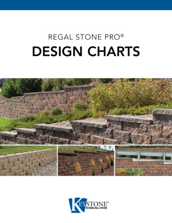
REGAL STONE PRO DESIGN CHARTS
REGAL STONE PRO - DESIGN CHARTSDESIGN/ESTIMATINGCHARTSThis section contains Keystone's design/estimating charts for Regal Stone Pro seriesgravity walls or geogrid-reinforced walls. The gravity wall charts help determine themaximum possible gravity wall height before geogrid reinforcement is required.The wall charts consider multiple factors for determining gravity wall stability and thenecessary geogrid length. First, determine the wall load condition that most closelyresembles the final project conditions. Then select the soil condition that most closelymatches the project site soils. Finally, select the wall height (including embedment) that willbest fit the project wall profile.The design/estimating charts in this section are to be used for reference and preliminarydesign and estimating only. These charts are not to be considered as a standardizedengineering document. A qualified professional should be consulted for final designassistance. Keystone accepts no liability for the use of these charts.The information contained herein has been compiled by Keystone Retaining Wall Systems LLC and to the best of our knowledge, accurately represents the Keystone product used in the applications which are illustrated.Final determination of the suitability for the use contemplated and its manner of use are the sole responsibility of the user. Design and analysis shall be performed by a qualified engineer.2Keystone Construction ManualRegal Stone Pro Units
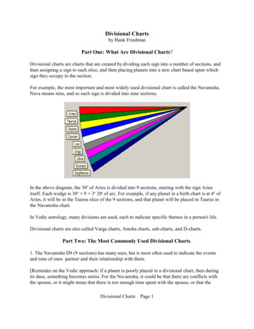
B:1 - MAXIMUM HEIGHT GRAVITY WALLSlopeTotalHeight1Retaining Soil Type1-inch Setback - Regal Stone Pro MAX HGT.ONE INCH SETBACK WALL(1" (25mm) min. setback per unit)BACKSLOPESoil 2.00'Silty Sand2.67'2.67'2.00'1.33'Silt/Lean Clay2.00'2.00'1.33' 1.00'NOTES: Wall height (H) is the total height from top to bottom. Minimum wall embedment should be 6-inches or one unit below grade, whichever is greater. (See page 11) Subsurface soils must be capable of supporting wall system. Unit drainage fill is ¾-inch clean crushed stone. Leveling pad is crushed stone base material. All backfill materials are compacted to minimum 95% standard proctor density or 92% modified proctor density. Finished grade must provide positive drainage. C alculations assume a unit weight of 120 Pcf for all soil types. Assumed angles for earth pressure calculations are: Sand/Gravel 34 ,Silty Sand 30 and Sandy Silt/Lean Clay 26 . Walls are non-critical structures with FS 1.5. Gravity wall charts are performed usingCoulomb earth pressure analysis. (NCMA 3rd Edition) Walls utilize 7 batter. No surcharges, except slopes, were used in the analysis. S urcharges or special loading conditions will reduce maximum wall heights. Sliding calculations assume a 6-inch crushed stoneleveling pad as compacted foundation material. The information provided is for preliminary design use only. A qualified professionalshould be consulted. Keystone accepts no liability for the use of these tables.REGAL STONE PRO ROCKFACE 3-PCThe information contained herein has been compiled by Keystone Retaining Wall Systems LLC and to the best of our knowledge, accurately represents the Keystone product used in the applications which are illustrated.Final determination of the suitability for the use contemplated and its manner of use are the sole responsibility of the user. Design and analysis shall be performed by a qualified engineer.3Keystone Construction ManualRegal Stone Pro UnitsREGAL STONE PRO - DESIGN CHARTSGravity Wall Schematic
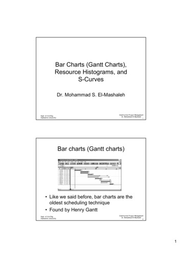
The Keystone reinforced wall charts are graphically presented to show the proper location and lengths of geogrids used with Keystone RegalStone Pro units at 1-inch setback batter (7 ). The chart includes design heights from 4.3 feet tall to 11 feet tall. Engineering judgment shouldbe used when interpolating between heights. In general, geogrid should be placed at the design elevation for the entire wall length or until awall step is reached. These preliminary design and estimating charts are for individual walls and do not apply to any tiered wall applications.Minimum reinforcement lengths were set for 4-feet and a 70% reinforcement length-to-wall height ratio. Top layers of geogrid shall neverbe more than 2 units from the top of the wall. Bottom layers of geogrid shall never be more than 2 units from the top of the leveling pad.Soil ranges were selected to approximate good, medium and poor soil conditions to cover the typical design range. Wall height is the totalheight of the wall from the top of the leveling pad to the top of the wall. The charts use Coulomb earth pressure theory, based on NCMA3rd Edition for calculations. The following charts assume the use of a coated polyester geogrid with a minimum allowable design strength of:LTDS 1,800 plf, Tal 1,200 plf. The following geogrid types are suitable with these design charts: (1) Miragrid 3XT by TC Mirafi, (2) Stratagrid200 by Strata Systems and (3) Synteen SF35 by Synteen. 250 psf surcharge is applied 6-inches behind the tail of the units.All geogrid lengths shown are the actual lengths of geogrid required as measured from the front wall face to the end of the geogrid. Thecharts assume that the walls are constructed in accordance with Keystone specifications and good construction practice. All soil zones(reinforced, retained, and foundation) must be compacted in 8-inch lifts to minimum 95% standard proctor density or 92% modified proctordensity as determined by laboratory testing. The information contained in the design/estimating charts are for preliminary design andestimating use only. A qualified professional should be consulted for final design assistance. Keystone accepts no liability for the use of thesecharts.B:2 - REINFORCED WALL SCHEMATICNOTES: Wall height (H) is thetotal height from top tobottom.SetbackKeystone Units Minimum wallembedment is 6-inches.Backslope or SurchargeCap UnitFinished Grade Subsurface soilsmust be capable ofsupporting the wallsystem.Low permeability SoilReinforced Soil Zone Leveling pad is crushedstone base material.Retained Soil ZoneWall HeightGeosyntheticReinforcementLimit of ExcavationEmbedmentUnit Drainage FillLeveling PadDrainage Collection Pipe Unit drainage fill is¾-inch clean crushedstone. All backfill materialsare compacted to95% standard proctordensity or 92%modified proctordensity. Geogrids must be ofappropriate type andlength per the design. Finished grade mustprovide positivedrainage. The symbol 5'indicates location andlength of geogridmeasured from the frontof the wall to the end ofthe geogrid.The information contained herein has been compiled by Keystone Retaining Wall Systems LLC and to the best of our knowledge, accurately represents the Keystone product used in the applications which are illustrated.Final determination of the suitability for the use contemplated and its manner of use are the sole responsibility of the user. Design and analysis shall be performed by a qualified engineer.4Keystone Construction ManualRegal Stone Pro UnitsREGAL STONE PRO - DESIGN CHARTSDesign/Estimating Charts: Reinforced Wall Charts
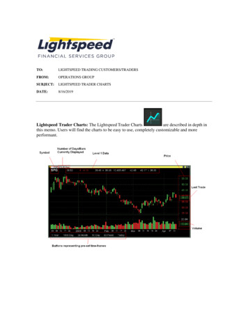
REGAL STONE PRO UNITS - 1-INCH SETBACKSAND/GRAVEL: 34 , 120 pcfCASE 1: Level - No SurchargeNO 8.0'7.0'6.0'REINFORCEDSOIL ZONE8.3’8.0'9.7’11.0’CASE 2: Level - 250 psf Surcharge250 PSF SURCHARGE8.0'7.0'H6.0'REINFORCEDSOIL 3’9.7’11.0’CASE 3: 3H:1V Backslope139.0'8.0'7.0'HREINFORCEDSOIL 9.7’9.0'11.0’The information contained herein has been compiled by Keystone Retaining Wall Systems LLC and to the best of our knowledge, accurately represents the Keystone product used in the applications which are illustrated.Final determination of the suitability for the use contemplated and its manner of use are the sole responsibility of the user. Design and analysis shall be performed by a qualified engineer.5Keystone Construction ManualRegal Stone Pro UnitsREGAL STONE PRO - DESIGN CHARTSDesign/Estimating Charts: Reinforced Wall Charts
REGAL STONE PRO UNITS - 1-INCH SETBACKSILTY SAND: 30 , 120 pcfCASE 1: Level - No SurchargeNO SURCHARGE8.0'8.0'REINFORCEDSOIL '8.0'9.7’8.0'11.0’CASE 2: Level - 250 psf Surcharge250 PSF 0'7.0'6.0'9.0'9.0'8.0'REINFORCEDSOIL ZONE9.7’11.0’CASE 3: 3H:1V .0'7.0'6.0'10.0'9.0'8.0'REINFORCEDSOIL ZONE9.7’10.0'11.0’The information contained herein has been compiled by Keystone Retaining Wall Systems LLC and to the best of our knowledge, accurately represents the Keystone product used in the applications which are illustrated.Final determination of the suitability for the use contemplated and its manner of use are the sole responsibility of the user. Design and analysis shall be performed by a qualified engineer.6Keystone Construction ManualRegal Stone Pro UnitsREGAL STONE PRO - DESIGN CHARTSDesign/Estimating Charts: Reinforced Wall Charts
REGAL STONE PRO UNITS - 1-INCH SETBACKSILT/LEAN CLAY: 26 , 120 pcfCASE 1: Level - No SurchargeNo Surcharge9.0'8.0'H7.0'ReinforcedSoil 3’9.7’11.0’CASE 2: Level - 250 psf Surcharge250 psf SurchargeH9.0'ReinforcedSoil Zone8.0'7.0'7.0'6.0'6.0'4.3’7.0’ENGINEER SHOULD EVALUATE DESIGN FORPOOR SOILS AND ’11.0’CASE 3: 3H:1V Backslope1H3ReinforcedSoil ZoneENGINEER SHOULD EVALUATE DESIGN FORPOOR SOILS AND .3’9.7’11.0’The information contained herein has been compiled by Keystone Retaining Wall Systems LLC and to the best of our knowledge, accurately represents the Keystone product used in the applications which are illustrated.Final determination of the suitability for the use contemplated and its manner of use are the sole responsibility of the user. Design and analysis shall be performed by a qualified engineer.7Keystone Construction ManualRegal Stone Pro UnitsREGAL STONE PRO - DESIGN CHARTSDesign/Estimating Charts: Reinforced Wall Charts
CHARTS This section contains Keystone's design/estimating charts for Regal Stone Pro series gravity walls or geogrid-reinforced walls. The gravity wall charts help determine the maximum possible gravity wall height before geogrid reinforcement is required. The wall charts consider multiple factors for determining gravity wall stability and the