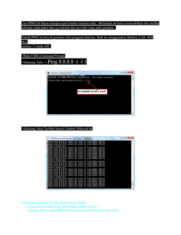
Transcription
Design Of A PI Rate Controller ForMitigating SIP OverloadYang Hong, Changcheng Huang, James YanDept. of Systems and Computer Engineering, Carleton University, Ottawa, CanadaE-mail: {yanghong, huang}@sce.carleton.ca, jim.yan@sympatico.caAbstract—Recent collapses of SIP servers in the carriernetworks (e.g., Skype outage) indicate that the built-in SIPoverload control mechanism cannot mitigate overload effectively.In this paper, by employing a control-theoretic approach thatmodels the interaction between an overloaded downstream serverand its upstream server as a feedback control system, weinvestigate the root cause of SIP server crash by studying theimpact of the retransmission on the queuing delay of theoverloaded server. Then we design a PI rate controller to mitigatethe overload by regulating the retransmission rate based on theround trip delay. We derive the guidelines for choosing PIcontroller gains to ensure the system stability. Our OPNETsimulation results demonstrate that our proposed controltheoretic approach can cancel the short-term SIP overloadeffectively, thus preventing widespread SIP network failure.I. INTRODUCTIONInternet protocol (IP) telephony is experiencing rapidlygrowing deployment due to its lower-cost telecommunicationssolutions for both consumer and business services. SIP(Session Initiation Protocol) [1] has become the mainsignaling protocol to setup, manage and terminate sessions forIP telephony applications such as Voice-over-IP, instantmessaging and video conferencing. 3rd Generation PartnershipProject (3GPP) has adopted SIP as the basis of its IPMultimedia Subsystem (IMS) architecture [2]. With the 3rdGeneration wireless technology being adopted by more andmore carriers, most cellular phones and other mobile devicesare starting to use or are in the process of supporting SIP forsession establishment te180Ringing200OKACKSession DataBye200OKBye200OKBye200OKFig. 1. A typical procedure of session establishment.Fig. 1 illustrates a basic operation of a SIP system. To setup a call, a user agent client (UAC) sends an “Invite” requestto a user agent server (UAS) via the two proxy servers. Theproxy server returns a provisional “100 (Trying)” response toconfirm the receipt of the “Invite” request. The UAS returns a“180 (Ringing)” response after confirming that the parametersare appropriate. It also evicts a “200 (OK)” message to answerthe call. The UAC sends an “ACK” response to the UAS afterreceiving the “200 (OK)” message. Finally the mediacommunication between the UAC and the UAS is establishedthrough the call session. The “Bye” request is generated toclose the session, thus terminating the communication.SIP introduces a retransmission mechanism to provide thereliable message delivery [1, 4]. In practice, a SIP sender usestimeout to detect message losses. One or more retransmissionswould be triggered if the corresponding reply message is notreceived in predetermined time intervals.When the message arrival rate exceeds the service capacityat a SIP server, overload occurs and the queue builds up,which may result in a long queuing delay and triggerunnecessary retransmissions from its upstream servers. Theredundant retransmissions increase the CPU loads of both theoverloaded server and its upstream servers. Such overloadpropagation may bring potential SIP network collapse [5-18].SIP RFC 3261 [1] suggests that the SIP retransmissionmechanism should be disabled for hop-by-hop transactionwhen running SIP over TCP to avoid redundantretransmissions at both SIP and TCP layer [1]. However,nearly all vendors choose to run SIP over UDP instead of TCPfor the following reasons [5-19]: (1) The overhead of statemanagement such as three-way handshake prevents TCP fromreal-time application which is a critical requirement for SIPprotocol; (2) Designed for preventing congestion caused bybandwidth exhaustion, the complex TCP congestion controlmechanism provides little help for SIP overload which iscaused by CPU constraint.RFC 5390 [20] identified the various reasons that maycause server overload in a SIP network. These include poorcapacity planning, component failures, flash crowds, denial ofservice attacks, etc. In general, anything that may trigger ademand burst or a server slowdown can cause server overloadand lead to server crash.The contributions of this paper are: (1) Extending classicalcontrol theory to model the impact of the retransmission rateon the queuing delay of an overload SIP server. As shown inEq. (6), we have used the frequency domain technique toaccomplish the modeling; (2) Developing a PI controller tomitigate the SIP overload by controlling retransmission rate
based on the round trip delay (i.e., the approximated queuingdelay as discussed later on); (3) Providing the guidelines forobtaining PI controller parameters to guarantee the stability ofthe SIP overload control system. We perform OPNETsimulation to validate the efficiency of the proposed controltheoretical approach on SIP overload control.II. RELATED WORKRecent collapses of SIP servers in carrier networks (e.g.,Skype outage [21]) have motivated numerous overload controlsolutions (e.g., [5-15]). For example, both centralized anddistributed overload control mechanisms for SIP weredeveloped in [9]. Three window-based feedback algorithmswere proposed to adjust the message sending rate of theupstream SIP servers based on the queue size or queuing delay[10]. Retry-after control, processor occupancy control, queuedelay control and window based control were proposed toimprove goodput and prevent overload collapse in [6].However, these overload control proposals suggested thatthe overloaded receiving server informs its upstream sendingservers to reduce their original message sending rates. Suchpushback control solution would increase the queuing delaysof newly arrival original messages at the upstream servers,which in turn cause overload at the forwarding upstreamservers. Overload may thus propagate server-by-server tosources and block large amount of calls which means therevenue loss for carriers.Since unnecessary retransmissions caused by overloadwould exacerbate the overload [15], different from all existingsolutions discussed above, our goal for mitigating the overloadis to reduce the retransmission rate only. Controllingretransmission rate based on redundant retransmission ratiowas proposed in [22]. However, redundant retransmissionmessages can only be detected after their correspondingresponse messages are received, such delay might lead tosluggish reaction and potential throughput loss. The queuingdelay has been well accepted as a more reliable indicator ofoverload by some push-back solutions (e.g., [5, 10]), therefore,in this paper, we propose to control retransmission rate basedon the queuing delay of an overloaded server which can beapproximated by the round trip delay of its upstream server.UAC 0UACUACUACUASProxy1Proxy2UASUASUASFig. 2. SIP network topology with an overloaded downstream receiving Server2 (which is marked with diagonal lines) and its upstream sending Server 1.III. PI CONTROLLER FOR MITIGATING SIP OVERLOADThe topology of a real SIP network can be quite complex.Fig. 2 depicts a typical SIP network topology [9]. To focus ourstudy on the interactions between overloaded receiving Server2 and its upstream sending Server 1, we assume the upstreamservers of Server 1 and the downstream servers of Server 2have sufficient capacity to process all arrival messages withoutany delay. Practical buffer sizes vary with the actual servicerates and system configuration plans. With the memorybecoming cheaper and cheaper, typical buffer sizes are likelyto become larger and larger. We assume that the buffer sizesfor all servers are large enough to hold all arrival messages.Given the proportionate nature and the general similarity ofthe retransmission mechanisms between the “Invite” and“non-Invite” messages in a typical session [1], this paper willfocus on the hop-by-hop Invite-100(Trying) transaction.A. Queuing Dynamics of Overloaded ServerFig. 3 depicts the queuing dynamics of Server 1 and Server2. There are two queues at each server: one to store themessages and the other to store the retransmission timers [9,12]. We can obtain the queuing dynamics for the messagequeue of Server 2 as(1)q 2 (t ) 2 (t ) r2 (t ) 2 (t ) 2 (t ) ,where q2(t) denotes the queue size and q2(t) 0; 2(t) denotesoriginal message rate; r2(t) denotes retransmission messagerate; 2(t) denotes response message rate; 2(t) denotes themessage service rate.100Trying responseInvite request 1(t)r1(t)r2' (t )Timer firesMessage buffer q1(t)Reset timerTimer expires qr1(t)Invite requestServer 2 2(t) 2 r2(t)Server 1 2(t)q2(t) 1(t)100Trying responseTimer starts 1Timer bufferFig. 3. Queuing dynamics of an overloaded server and its upstream server.Like Eq. (1), we can obtain the queuing dynamics for themessage queue of Server 1 as(2)q 1 (t ) 1 (t ) r1 (t ) r2 (t ) 1 (t ) 1 (t ) ,where q1(t) denotes the queue size and q1(t) 0; 1(t) denotesarbitrarily distributed original message rate, which mayfollows Poisson, Pareto, Gamma or Lognormal distribution;r1(t) denotes retransmission rate corresponding to 1(t); r'2(t)denotes retransmission message rate generated by Server 1 for 2(t); 1(t) denotes response message rate corresponding to 2(t); 1(t) denotes arbitrarily distributed service rate.When Server 2 performs its routine maintenance andreduces its service capacity for signaling messages, theoriginal message rate 2(t) is larger than the service rate 2(t),the queue size q2(t) tends to increase according to Eq. (1) (i.e.,q 2 (t ) 0 ). After a short period of overload, the queuing delayof Server 2 is long enough to trigger the retransmissions r'2(t)which enter the queue of Server 1. If the total new messagearrival rate of 1(t), 1(t) and r'2(t) is larger than the servicerate 1(t), the queue size q1(t) would increase (i.e., q 1 (t ) 0 ,as indicated by Eq. (2)) and may trigger the retransmissionsr1(t) to propagate the overload from Server 2 to Server 1. Afterqueuing and processing delay at Server 1, the retransmittedmessages r'2(t) enter Server 2 as r2(t) to increase the queue sizeq2(t) more quickly (as described by Eq. (1)), thus making theoverload at Server 2 much worse.B. Overload Control PlantIn order to present our overload control mechanism moreclearly, we assume that the upstream Server 1 can process allarrival messages without any delay before the overload is
propagated from its downstream Server 2, i.e., 2(t) 1(t) andr2(t) r'2(t). Therefore, we can update the queuing dynamics forthe message queue of Server 2 as(3)q 2 (t ) 1(t ) r2 (t ) 2 (t ) 2 (t ) .Then the corresponding message queuing delay of Server 2becomes(4) 2 (t ) [r2 (t ) 1(t ) 2 (t ) 2 (t )] / 2 (t ) .Each request message corresponds to a response message,and the time to process a response message is typically muchsmaller than a request message [1, 10]. Thus we can use therequest message service rate (i.e., the response message rate 1(t)) to approximate the total service rate 2(t). Then we canapproximate the queuing delay of Server 2 as(5) 2 (t ) [r2 (t ) 1 (t ) 2 (t ) 1 (t )] / 1 (t ) ,We assume that the system is locally stable and thereforethe uncontrolled variables 1, 2 and 1 are constant around anoperating point. Truncating the component ( 1 2 1) onlyhas impact on the zeros of closed-loop overload control system,and thus will not reduce the system stability margin. Therefore,the transfer function between the instantaneous queuing delay 2(t) and the retransmission rate r'2(t) can be approximated asP(s) 2(s)/r'2(s) ℒ{ 2(t)}/ℒ{r'2(t)} 1/( 1s).(6)Such control plant approximation has been widely adopted inindustrial process control system design, e.g., [23, 24], whichhas recently found its application in network traffic control,e.g., [25]. The validity of this approximation has also beenverified by our performance evaluation in Section IV.As processing signaling messages are typically CPUcapacity constrained rather than bandwidth constrained, for theround trip delay between an upstream server and itsoverloaded downstream server, the queuing delay is dominant,while transmission and propagation delay are negligible [10].Therefore, the round trip delay between the upstream Server 1and the downstream Server 2 can approximate the queuingdelay 2 of the overloaded downstream Server 2 when theoverload happens.C. The PI Rate Controller DesignAs the retransmitted messages r'2(t) may increase queuesizes at both Server 1 and Server 2 and bring the overload toboth servers, we propose a PI rate control algorithm that canmitigate the overload by reducing the retransmission rate r'2(t),thus preventing the network collapse (such as Skype outage[21]) caused by overload propagation. 0 e(t) C(s)r'2(t)P(s) 2(t)G(s)Fig. 4. Feedback SIP overload control system.Fig. 4 depicts a feedback SIP overload control system,where the overload control plant P(s) represents the interactionbetween an overloaded downstream receiving server and itsupstream sending server, and adaptive PI rate controller C(s) islocated at the upstream server for mitigating the overload toclamp the round trip delay of the upstream server (i.e., theapproximated queuing delay of the overloaded downstreamserver) below a target value, when the overload is anticipatedat its downstream server.Based on the instantaneous round trip delay of theupstream server (which approximates the queuing delay of theoverloaded downstream server) 2(t), the retransmission rater'2(t) can be obtained by the following PI control algorithmexpressed viatr2 (t ) K P e(t ) K I 0 e( )d t K P ( 0 2 (t )) K I 0 ( 0 2 ( ))d .(7)where KP and KI denote the proportional gain and integral gainof the PI controller at the upstream server, and 0 denotes thetarget round trip delay. In the real-time implementation, aretransmission probability is equal to the ratio between theretransmission rate r'2(t) and the measured timer expirationrate. Since the original message rate is maintained to keep therevenue and achieve the user satisfaction in case of theoverload, PI controller aims at clamping the round trip delayof the upstream server below a desirable target delay 0 ratherthan reaching the target delay 0.It can be easy to obtain the transfer function between theretransmission rate r'2(t) and the round trip delay deviation e(t)asC(s) KP KI/s.(8)Then the open-loop transfer function of overload controlsystem becomesG(s) C(s)P(s) (KP KI/s)/( 1s).(9)From the definition on the phase margin m of G(s) [26],we can obtain K P g arctan (10) m , KI 2 2K P2 g2 K I21 K P2 g2 K I2 1,(11) g 1 g 1 g2where g is the gain crossover frequency of the overloadcontrol system. It is well known that a positive phase margin( m 0) can guarantee the stability of the control system inaccordance with the Nyquist Stability Theorem [23-26]. Acommon control engineering practice suggests an interval ofphase margin as 300 m 600 for a good response [24]. Tosimplify our controller design, we set g 1 based on numeroussimulation results. Thus we can obtain KP and KI as 1 tan( m ) 1KP , KI .(12)1 tan 2 ( m )1 tan 2 ( m )So far we have assumed 1 be constant. In reality, this is notnecessarily true. If the PI controller parameters KP and KIremain unchanged, the varying service rate of the overloadedserver may drive the phase margin out of its desirable interval.Lemma 1 shows the impact of the response message rate onthe phase margin of the overload control system. We omit theproof due to page limit.Lemma 1: If current response message rate '1 is larger thanprevious response message rate 1 (that is, '1 1) and the PIcontroller is designed based on 1, then the overload controlsystem with '1 will have less phase margin than that with 1(that is, 'm m).To achieve a satisfactory performance, we self-tune PIcontroller when dramatic change of message response rate 1exceeds a specified interval. Summary of our overload controlalgorithm is shown in Fig. 5.
Fixed parameter: : Target round trip delay m : Phase marginFig. 5. A PI rate control algorithm for mitigating SIP overload.IV. PERFORMANCE EVALUATION AND SIMULATIONTo verify our PI controller, we conducted OPNETsimulations to observe the dynamic behaviour of theoverloaded server and its upstream server. During ourexperiment, four user agent clients generated original requestmessages with equal rate, and then sent them to four useragent servers via two proxy servers, as shown in Fig. 2. Themessage generation rates are Poisson distributed 1 . Themessage service rate of each server is also Poisson distributed.Since processing a response message takes much less timethan processing a request message, we set the ratio α of themean processing time of a response message to that of arequest message as α 0.5. The mean service capacity of aproxy server is 1000 messages/sec measured based on theprocessing time of request message, i.e. C1 C2 1000 requestmessages/s. That is, the mean processing times for a requestmessage and a response message are 1ms and 0.5msrespectively. The mean service capacity of a UAC or a UAS isequal to 500 request messages/sec. The total message servicerate is bounded by the service capacity C at each server, i.e., C. The target delay 0 is set as 0.5s. The phase margin is setas 450. The Internet Traffic Report indicates that current globalpacket loss statistic averaged 8% packet loss [27], consideringpossible message corruption in the SIP layer, average messageloss probability is set as 10%.To demonstrate the effectiveness of our overload controlsolution, two typical overload scenarios were simulated: (1)Overload at Server 1 due to a demand burst; (2) Overload atServer 2 due to a server slowdown. The simulation time is 90s,1The workload in the real SIP networks can be arbitrarily distributed, whichmay follows Poisson, Pareto, Gamma or Lognormal distribution. Poissondistributed message arrival rate and service rate are widely adopted by mostexisting research work (e.g., [10]).NOLC q1OLC q165432100102030405060708010NOLC q0OLC q08900066000430002090Time (sec)01020304050607080012000x 107OLC Queue size q (messages)Varying parameter: : Instantaneous round trip delay : Response message rateKP : Proportional gain of PI controllerKI : Integral gain of PI controllerr'2 : Message retransmission rate48NOLC Queue size q0 (messages)(2) Measure and upon response messagearrivals.(3) If 1.5 or 0.5 , self-tune PIcontroller gains using Eq. (12), then update ; Otherwise, PI controller remainsunchanged.(4) Calculate the retransmission rate r'2 usingEq. (7); Go to Step (2).A. Overload at Server 1In this scenario, the mean message generation rate for eachuser agent client was 200 messages/sec (i.e., 1 800messages/sec, emulating a short surge of user demands) fromtime t 0s to t 30s, and 50 messages/sec (i.e., 1 200messages/sec, emulating regular user demands) from timet 30s to t 90s. The mean service capacities of two proxyservers were C1 C2 1000 messages/sec.090Time (sec)(a)(b)Fig. 6. (a) Queue size q1 (messages) of Server 1 versus time. (b) Queue size q0(messages) of UAC 0 versus time.Figs. 6 and 7(a) show the dynamic behaviour ofoverloaded Server 1 and its upstream UAC 0.16001200Retransmission rate (msgs/sec)(1) Specify target queuing delay and phasemargin m; Set the initial values for ; ObtainPI controller gains using Eq. (12).Queue size q1 (messages)When each retransmission timer fires or expiresRetransmit the message with a retransmissionprobability corresponding to a retransmissionrate r'2 calculated by a PI rate controllerAdaptive PI rate control algorithm:and the 1st-time retransmission timer is T1 500ms [1]. In eachscenario, we performed our simulations with overload controlalgorithm and without overload control algorithm separately.In all the simulation plots in this paper, we use“OLC”/“NOLC” to indicate that overload control algorithm“was”/“was not” applied to all servers in the SIP network.1400Message rate (msgs/sec)Overload Control Algorithm12001000NOLC 1800OLC 1600OLC r1NOLC r1400200001020304050Time (sec)607080901000800NOLC r1OLC r1600NOLC r 2OLC r2 40020000102030405060708090Time (sec)(a)(b)Fig. 7. (a) Scenario A: Moving average original message rate 1 (messages/sec)of Server 1 and moving average retransmission rate r1 (messages/sec) forServer 1 versus time. (b) Scenario B: Moving average retransmission rate r1(messages/sec) for Server 1 and moving average retransmission rate r 2(messages/sec) for Server 2 versus time.Without overload control algorithm applied, it is easy to seefrom Fig. 6(a) that Server 1 became CPU overloadedimmediately and the overload deteriorated as time evolves,leading to the eventual crash of Server 1. Since the aggregateservice capacity of four user agent clients was larger than thatof proxy Server 1, the queue size of each user agent clientdecreased slowly (see Fig. 6(b)) after new original messagegeneration rates decreased.Our overload control algorithm made the queue size ofServer 1 increase slowly during the period of the demand burst,and cancelled the overload at Server 1 within 27s (11s fasterthan the overload control algorithm in [22]) after the new userdemand rate reduced at time t 30s.B. Overload at Server 2In this scenario, the mean server capacities of the twoproxy servers were C1 1000 messages/sec from time t 0s to
t 90s, C2 100 messages/sec from time t 0s to t 30s, andC2 1000 messages/sec from time t 30s to t 90s. The meanmessage generation rate for each user agent client was 50messages/sec.41048OLC q13624120010203040506070800902[2][3]x 101.8Queue size q2 (messages)NOLC q1OLC Queue size q1 (messages)1NOLC Queue size q (messages)54x 10REFERENCES[1]NOLC q21.6[4]OLC q21.41.210.8[5]0.60.40.20010Time (sec)2030405060708090Time (sec)(a)(b)Fig. 8. (a) Queue size q1 (messages) versus time. (b) Queue size q2 (messages)versus time.Without overload control algorithm applied, Figs. 7(b) and8 demonstrate that Server 2 became overloaded first, whichwas followed by a later overload at Server 1. The queue size atServer 1 increased more quickly due to the extra work load forhandling retransmissions for both Server 1 and Server 2. AfterServer 2 resumed its normal service at time t 30s, Server 1and Server 2 had the same service capacity. Because Server 1had to process part of r1 which would not enter Server 2, thetotal arrival rate at Server 2 was less than its service capacity.Eventually the overload at Server 2 was cancelled, while theoverload at Server 1 persisted (see Fig. 8).With our overload control algorithm applied, the overloadat Server 2 was mitigated and the queue size of Server 2increased relatively slowly. In the mean time, Server 1 hadenough capacity to process the limited retransmissions forServer 2, thus maintaining a small queue. After Server 2resumed its normal service, it only spent 7s (2s faster than theoverload control algorithm in [22]) to cancel the overload andthe buffer became empty at time t 37s.V. CONCLUSIONSIn order to study the impact of the retransmission rate onthe queuing delay of an overloaded server, we have employeda control-theoretic approach to model the interaction betweenthe overloaded downstream receiving server and its upstreamsending server as a feedback control system. Then we havedeveloped a novel PI rate control algorithm to mitigate theoverload by reducing retransmission rate only, whilemaintaining the original message rate to avoid excessiverevenue loss.By analyzing queuing dynamics and performing OPNETsimulations, we have demonstrated that without overloadcontrol algorithm applied, the overload at downstream servermay propagate or migrate to its upstream servers eventually.Our overload control algorithm can cancel the short-termoverload effectively and prevent the overload propagation.Without requiring modification in the SIP header and thecooperation among different carriers in different countries, anycarrier can freely implement our proposed solution in its SIPservers to avoid potential widespread server crash.ACKNOWLEDGMENTThis work was supported by the NSERC grant #CRDPJ354729-07 and the OCE grant J. Rosenberg et al., “SIP: Session Initiation Protocol,” IETF RFC 3261,June 2002.“3rd Generation Partnership Project”. http://www.3gpp.org.S.M. Faccin, P. Lalwaney, and B. Patil, “IP Multimedia Services:Analysis of Mobile IP and SIP Interactions in 3G Networks,” IEEECommunications Magazine, 42(1), January 2004, pp. 113-120.M. Govind, S. Sundaragopalan, K.S. Binu, and S. Saha, “Retransmissionin SIP over UDP - Traffic Engineering Issues,” in Proceedings ofInternational Conference on Communication and BroadbandNetworking, Bangalore, India, May 2003.E. Noel and C.R. Johnson, “Initial simulation results that analyze SIPbased VoIP networks under overload,” in Proceedings of 20thInternational Teletraffic Congress, Ottawa, Canada, 2007, pp. 54-64.E. Noel and C.R. Johnson, “Novel Overload Controls for SIPNetworks,” in Proceedings of 21st International Teletraffic Congress,Paris, France, 2009.R.P. Ejzak, C.K. Florkey, and R.W. Hemmeter, “Network Overload andCongestion: A comparison of ISUP and SIP,” Bell Labs TechnicalJournal, 9(3), 2004, pp. 173–182.M. Ohta, “Overload Control in a SIP Signaling Network,” in Proceedingof World Academy of Science, Engineering and Technology, Vienna,Austria, March 2006, pp. 205—210.V. Hilt and I. Widjaja, “Controlling Overload in Networks of SIPServers,” in Proceedings of IEEE ICNP, Orlando, Florida, October 2008,pp. 83-93.C. Shen, H. Schulzrinne, and E. Nahum, “SIP Server Overload Control:Design and Evaluation,” in Proceedings of IPTComm, Heidelberg,Germany, July 2008.A. Abdelal and W. Matragi, “Signal-Based Overload Control for SIPServers,” in Proceedings of IEEE CCNC, Las Vegas, NV, January 2010.“SIP Express Router” http://www.iptel.org/ser/.T. Warabino, Y. Kishi, and H. Yokota, “Session Control CooperatingCore and Overlay Networks for “Minimum Core” Architecture,” inProceedings of IEEE Globecom, Honolulu, Hawaii, December 2009.I. Dacosta, V. Balasubramaniyan, M. Ahamad, and P. Traynor,“Improving Authentication Performance of Distributed SIP Proxies,”Proceedings of IPTComm, Atlanta, GA, July 2009.J. Sun, R.X. Tian, J.F. Hu, and B. Yang, “Rate-based SIP FlowManagement for SLA Satisfaction,” in Proceedings of 11th InternationalSymposium on Integrated Network Management (IEEE/IFIP IM), NewYork, USA, June 2009, pp. 125-128.V. Hilt and H. Schulzrinne, “Session Initiation Protocol (SIP) OverloadControl,” IETF Internet-Draft, January 2011.Y. Hong, C. Huang, and J. Yan, “Analysis of SIP RetransmissionProbability Using a Markov-Modulated Poisson Process Model,” inProceedings of IEEE/IFIP Network Operations and ManagementSymposium, Osaka, Japan, April 2010, pp. 179–186.E.M. Nahum, J. Tracey, and C.P. Wright, “Evaluating SIP serverperformance,” in Proceedings of International Conference onMeasurement and Modeling of Computer Systems (ACM SIGMETRICS),San Diego, CA, US, 2007, pp. 349–350.Y. Hong, O. W. W. Yang, and C. Huang, “Self-Tuning PI TCP FlowController for AQM Routers With Interval Gain and Phase MarginAssignment,” in Proceedings of IEEE Globecom, Dallas, TX, U.S.A,November 2004, pp. 1324-1328.J. Rosenberg, “Requirements for Management of Overload in theSession Initiation Protocol,” IETF RFC 5390, December 2008.R. Ando, “Internet phone and video service Skype went down in a globalservice outage,” Reuters News, December 22nd, 2010.Y. Hong, C. Huang, and J. Yan, “Mitigating SIP Overload Using aControl-Theoretic Approach,” in Proceedings of IEEE Globecom,Miami, FL, U.S.A, December 2010.W.K. Ho, T.H. Lee, H.P. Han, and Y. Hong, “Self-Tuning IMC-PIDControl with Interval Gain and Phase Margin Assignment,” IEEE Trans.on Control Systems Technology, 9(3), May 2001, pp. 535-541.W.K. Ho, Y. Hong, A. Hansson, H. Hjalmarsson, and J.W. Deng, “RelayAuto-Tuning of PID Controllers Using Iterative Feedback Tuning,”Automatica, 39(1), January 2003, pp. 149-157.D. Katabi, M. Handley, and C. Rohrs, “Congestion Control for HighBandwidth Delay Product Networks”, in Proceedings of ACMSIGCOMM, August 2002.K. Ogata, Modern Control Engineering, fourth edition, Prentice Hall,New Jersey, 2002.“Internet Traffic Report”, http://www.internettrafficreport.com/, 2010.
Fig. 2. SIP network topology with an overloaded downstream receiving Server 2 (which is marked with diagonal lines) and its upstream sending Server 1. 0 III. PI CONTROLLER FOR MITIGATING SIP OVERLOAD The topology of a real SIP network can be quite complex. Fig. 2 depicts a typical SIP network topology [9]. To focus our