Transcription
Cisco Icons and Symbols1
Data NetworksSharing data through the use of floppy disks is not an efficientor cost-effective manner.Businesses needed a solution that would successfully addressthe following three problems: How to avoid duplication of equipment and resources How to communicate efficiently How to set up and manage a networkBusinesses realized that networking technology could increaseproductivity while saving money.2
Networking DevicesEquipment that connects directly to a network segment isreferred to as a device.These devices are broken up into two classifications. End-user devices Network devicesEnd-user devices include computers, printers, scanners, andother devices that provide services directly to the user.Network devices include all the devices that connect the enduser devices together to allow them to communicate.3
Network Interface CardA network interface card (NIC) is a printed circuit boardthat provides network communication capabilities to andfrom a personal computer. Also called a LAN adapter.4
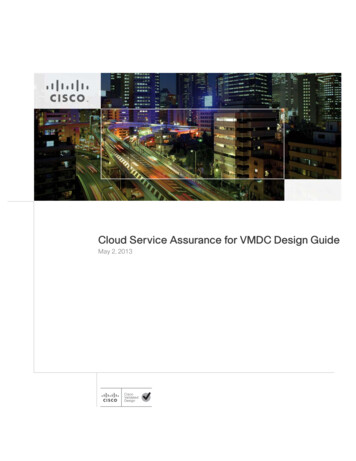
HubConnects a group of Hosts5
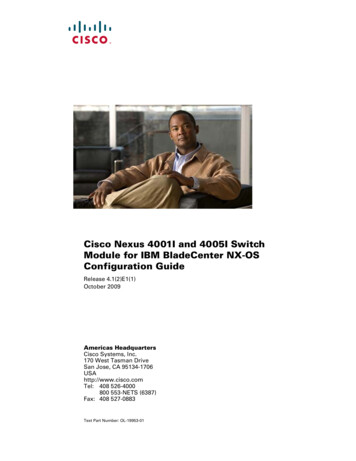
SwitchSwitchesaddmoreintelligence to data transfermanagement.6
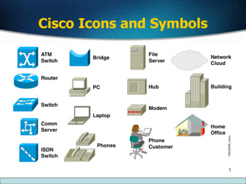
Router Routers are used to connect networks together Route packets of data from one network to another Cisco became the de facto standard of routers because of their highquality router products Routers, by default, break up a broadcast domain7
Network TopologiesNetwork topology defines the structure of the network.One part of the topology definition is the physical topology,which is the actual layout of the wire or media.The other part is the logical topology,which defines how themedia is accessed by the hosts for sending data.8
Bus Topology A bus topology uses a single backbone cable that isterminated at both ends. All the hosts connect directly to this backbone.9
Ring Topology A ring topology connects one host to the next and the lasthost to the first. This creates a physical ring of cable.10
Star Topology A star topology connects all cables to a central point ofconcentration.11
Extended Star Topology An extended star topology links individual stars together byconnecting the hubs and/or switches.This topology can extendthe scope and coverage of the network.12
Mesh Topology A mesh topology is implemented to provide as muchprotection as possible from interruption of service. Each host has its own connections to all other hosts. Although the Internet has multiple paths to any onelocation, it does not adopt the full mesh topology.13
Physical and Logical Topology14
LANs, MANs, & WANs One early solution was the creation of local-area network(LAN) standards which provided an open set of guidelines forcreating network hardware and software, making equipmentfrom different companies compatible. What was needed was a way for information to moveefficiently and quickly, not only within a company, but alsofrom one business to another. The solution was the creation of metropolitan-area networks(MANs) and wide-area networks (WANs).15
LANs16
WANs17
Virtual Private NetworkA VPN is a private network that is constructed within a public networkinfrastructure such as the global Internet. Using VPN, a telecommutercan access the network of the company headquarters through theInternet by building a secure tunnel between the telecommuter’s PCand a VPN router in the headquarters.18
Bandwidth19
Measuring Bandwidth20
Internetworking Devices21
What Are The Components Of ANetwork ?MobileUsersHomeOfficeInternetBranch OfficeMain Office22
Network Structure &HierarchyCore LayerDistributionLayerAccessLayer23
Institute of Electrical and ElectronicsEngineers (IEEE) 802 Standards IEEE 802.1: Standards related to network management. IEEE 802.2: General standard for the data link layer in the OSIReference Model. The IEEE divides this layer into two sublayers -the logical link control (LLC) layer and the media access control(MAC) layer. IEEE 802.3: Defines the MAC layer for bus networks that useCSMA/CD. This is the basis of the Ethernet standard. IEEE 802.4: Defines the MAC layer for bus networks that use atoken-passing mechanism (token bus networks). IEEE 802.5: Defines the MAC layer for token-ring networks. IEEE 802.6: Standard for Metropolitan Area Networks (MANs)24
25
Why do we need the OSI Model? To address the problem of networks increasing in size and in number, theInternational Organization for Standardization (ISO) researched manynetwork schemes and recognized that there was a need to create a networkmodel This would help network builders implement networks that couldcommunicate and work together ISO therefore, released the OSI reference model in 1984.26
Don’t Get Confused.ISO - International Organization for StandardizationOSI - Open System InterconnectionIOS - Internetwork Operating SystemTo avoid confusion, some people say “InternationalStandard Organization.”27
The OSI Reference Model7 Application6 Presentation5 SessionThe OSI Model will beused throughout yourentire networkingcareer!4 Transport3 Network2 Data LinkMemorize it!1 Physical28
OSI onSessionTransportNetworkData-LinkData FlowLayersPhysical29
Layer 7 - The Application Layer7 Application6 PresentationThis layer deal withnetworkingapplications.5 Session4 Transport3 Network2 Data Link1 PhysicalExamples: Email Web browsersPDU - User DataEach of the layers have Protocol Data Unit (PDU)30
Layer 6 - The Presentation Layer7 Application6 Presentation5 Session4 Transport3 NetworkThis layer is responsiblefor presenting the data inthe required format whichmay include: Code Formatting Encryption Compression2 Data Link1 PhysicalPDU - Formatted Data31
Layer 5 - The Session Layer7 Application6 Presentation5 Session4 Transport3 Network2 Data Link1 Physical This layer establishes, manages, andterminatessessionsbetweentwocommunicating hosts. Creates Virtual Circuit Coordinates communication between systems Organize their communication by offeringthree different modes Simplex Half Duplex Full DuplexExample: Client Software( Used for logging in)PDU - Formatted Data32
Half Duplex It uses only one wire pair with a digital signal running inboth directions on the wire. It also uses the CSMA/CD protocol to help preventcollisions and to permit retransmitting if a collision doesoccur. If a hub is attached to a switch, it must operate in halfduplex mode because the end stations must be able todetect collisions. Half-duplex Ethernet—typically 10BaseT—is only about30 to 40 percent efficient because a large 10BaseTnetwork will usually only give you 3 to 4Mbps—at most.33
Full DuplexIn a network that uses twisted-pair cabling, one pair is used to carry the transmittedsignal from one node to the other node. A separate pair is used for the return orreceived signal. It is possible for signals to pass through both pairs simultaneously.The capability of communication in both directions at once is known as full duplex.34
Layer 4 - The Transport Layer7 Application6 Presentation This layer breaks up the data from thesending host and then reassembles it in thereceiver.2 Data Link It also is used to insure reliable datatransport across the network. Can be reliable or unreliable Sequencing Acknowledgment Retransmission Flow Control1 PhysicalPDU - Segments5 Session4 Transport3 Network35
Layer 3 - The Network Layer7 Application6 Presentation5 Session4 Transport3 Network2 Data Link Sometimes referred to as the “Cisco Layer”. End to End Delivery Provide logical addressing that routers use forpath determination Segments are encapsulated Internetwork Communication Packet forwarding Packet Filtering Makes “Best Path Determination” FragmentationPDU – Packets – IP/IPX1 Physical36
Layer 2 - The Data Link Layer Performs Physical Addressing This layer provides reliable transit ofdata across a physical link. Combines bits into bytes andbytes into frames Access to media using MAC address Error detection, not correction LLC and MAC Logical Link Control performs Linkestablishment MAC Performs Access method7 Application6 Presentation5 Session4 Transport3 Network2 Data Link1 PhysicalPreambleDMACPDU - FramesSMACData lengthDATAFCS37
Layer 1 - The Physical Layer7 Application6 Presentation5 Session4 Transport3 Network2 Data Link1 Physical This is the physical mediathroughwhichthedata,represented as electronic signals,is sent from the source host tothe destination host. Move bits between devices EncodingPDU - Bits38
Data ayer DataTCP HeaderTransportUpper-Layer DataIP HeaderDataLLC HeaderDataFCSMAC acketData-LinkFramePhysicalBits39
Data Encapsulation40
OSI Model AnalogyApplication Layer - Source HostAfter riding your new bicycle a few times inHyderabad, you decide that you want to give it toa friend who lives in DADAR, Mumbai.41
OSI Model AnalogyPresentation Layer - Source HostMake sure you have the proper directions todisassemble and reassemble the bicycle.42
OSI Model AnalogySession Layer - Source HostCall your friend and make sure you have hiscorrect address.43
OSI Model AnalogyTransport Layer - Source HostDisassemble the bicycle and put different piecesin different boxes. The boxes are labeled“1 of 3”, “2 of 3”, and “3 of 3”.44
OSI Model AnalogyNetwork Layer - Source HostPut your friend's complete mailing address (andyours) on each box.Since the packages are toobig for your mailbox (and since you don’t haveenough stamps) you determine that you need to45go to the post office.
OSI Model AnalogyData Link Layer – Source HostHyderabad post office takes possession of theboxes.46
OSI Model AnalogyPhysical Layer - MediaThe boxes are flown from Hyderabad to Mumbai.47
OSI Model AnalogyData Link Layer - DestinationDadar post office receives your boxes.48
OSI Model AnalogyNetwork Layer - DestinationUpon examining the destination address,Dadar post office determines that yourboxes should be delivered to your writtenhome address.49
OSI Model AnalogyTransport Layer - DestinationYour friend calls you and tells you he got all 3boxes and he is having another friend namedBOB reassemble the bicycle.50
OSI Model AnalogySession Layer - DestinationYour friend hangs up because he is done talkingto you.51
OSI Model AnalogyPresentation Layer - DestinationBOB is finished and “presents” the bicycle toyour friend. Another way to say it is that yourfriend is finally getting him “present”.52
OSI Model AnalogyApplication Layer - DestinationYour friend enjoys riding his new bicycle inDadar.53
Data Flow Through a Network54
Type of Transmission Unicast Multicast Broadcast55
Type of Transmission56
Broadcast Domain A group of devices receiving broadcast framesinitiating from any device within the group Routers do not forward broadcast frames,broadcast domains are not forwarded from onebroadcast to another.57
Collision The effect of two nodes sending transmissionssimultaneously in Ethernet. When they meet on thephysical media, the frames from each node collide andare damaged.58
Collision Domain The network area in Ethernet over which framesthat have collided will be detected. Collisions are propagated by hubs and repeaters Collisions are Not propagated by switches,routers, or bridges59
Physical LayerDefines Signaling type802.3 Connector typePhysical Media type802.3 is responsible for LANs based on the carrier sense multiple accesscollision detect (CSMA/CD) access methodology. Ethernet is an exampleof a CSMA/CD network.60
Physical Layer:Ethernet/802.310Base2—Thin Ethernet10Base5—Thick EthernetHostHub10BaseT—Twisted PairHosts61
Device Used At Layer 1PhysicalABCD All devices are in the same collision domain. All devices are in the same broadcast domain. Devices share the same bandwidth.62
Hubs & Collision Domains More end stations meansmore collisions. CSMA/CD is used.63
Layer 2MAC Layer—802.3Number of Bytes866Preamble Destination Address Source Address0000.0CIEEE CSEthernet IIuses “Type”here anddoes not use802.2.MAC Addresssynchronize senders and receivers64
Devices On Layer 2(Switches & Bridges)Data-Link1234OR12 Each segment has its own collision domain. All segments are in the same broadcast domain.65
SwitchesSwitchMemory Each segment is itsown collision domain. Broadcasts areforwarded to allsegments.66
Data-Link Defines pathsthrough networkIP, IPX802.2Physical Defines logicalsource anddestinationaddressesassociated with aspecific protocolNetworkLayer 3 : Network Layer802.3EIA/TIA-232V.3567
Layer 3 : (cont.)Network Layer End-Station PacketIP sData172.15.1.1NetworkNode Route determination occurs at this layer, so a packet must include a source anddestination address. Network-layer addresses have two components: a network component forinternetwork routing, and a node number for a device-specific address. Theexample in the figure is an example of an IP packet and address.68
Layer 3 (cont.)AddressMask172.16.122.204 255.255.0.017216122204BinaryAddress 10101100 00010000 01111010 11001100255BinaryMask25511111111 11111111Network0000000000 00000000Host69
Device On Layer 3Router Broadcast control Multicast control Optimal pathdetermination Traffic management Logical addressing Connects to WANservices70
Layer 4 : Transport Layer Defines flow control Provides reliable orunreliable services fordata transferNetwork Establishes end-to-endconnectivity betweenapplicationsTransport Distinguishes betweenupper-layer applicationsTCPUDPIPSPXIPX71
Reliable ServiceSenderReceiverSynchronizeAcknowledge, SynchronizeAcknowledgeConnection EstablishedData Transfer(Send Segments)72
How They OperateHubBridgeSwitchRouterCollision Domains:14Broadcast Domains:11441473
74
Why Another Model?Although the OSI reference model is universally recognized, thehistorical and technical open standard of the Internet isTransmission Control Protocol / Internet Protocol (TCP/IP).The TCP/IP reference model and the TCP/IP protocol stackmake data communication possible between any twocomputers, anywhere in the world, at nearly the speed of light.The U.S. Department of Defense (DoD) created the TCP/IPreference model because it wanted a network that could survive75any conditions, even a nuclear war.
TCP/IP Protocol ta-Link11PhysicalPhysical76
Application Layer OverviewApplicationTransportInternetFile Transfer- TFTP*- FTP*- NFSE-Mail- SMTPRemote Login- Telnet*- rlogin*Network Management- SNMP*Name Management- DNS*Data-Link*Used by the RouterPhysical77
Transport Layer OverviewApplicationTransportTransmission ControlProtocol (TCP)ConnectionOrientedUser DatagramProtocol (UDP)ConnectionlessInternetData-LinkPhysical78
TCP Segment FormatBit 0Bit 15 Bit 16Source Port (16)Bit 31Destination Port (16)Sequence Number (32)Acknowledgment Number (32)HeaderLength (4)Reserved (6) Code Bits (6)Checksum (16)20BytesWindow (16)Urgent (16)Options (0 or 32 if Any)Data (Varies)79
Port DNSTFTPSNMPRIP2123255369161520TCPPortNumbersUDP80
TCP Port NumbersSourcePortDestinationPort Telnet ZHost ZHost ASPDP102823 Destination port 23.Send packet to myTelnetapplication.81
TCP Port Numbers82
TCP Three-WayHandshake/Open ConnectionHost A1Host BSend SYN(seq 100 ctl SYN)SYN ReceivedSYN Received3Established(seq 101 ack 301ctl ack)Send SYN, ACK 2(seq 300 ack 101ctl syn,ack)83
Opening & Closing Connection84
Windowing Windowing in networking means the quantity of datasegments which is measured in bytes that a machine cantransmit/send on the network without receiving anacknowledgement85
TCP Simple AcknowledgmentSenderReceiverSend 1Receive 1Send ACK 2Receive ACK 2Send 2Receive 2Send ACK 3Receive ACK 3Send 3Receive 3Send ACK 4Receive ACK 4 Window Size 186
TCP Sequence andAcknowledgment NumbersSourcePortDestinationPortI justsent number11.SequenceAcknowledgment I just got number11, now I neednumber 12.Source Dest. Seq. Ack.10282310100Source Dest. Seq. Ack.23 1028 10011Source Dest. Seq. Ack.10282311101Source Dest. Seq. Ack.231028 1011287
Windowing There are two window sizes—one set to 1 and one set to3. When you’ve configured a window size of 1, the sendingmachine waits for an acknowledgment for each datasegment it transmits before transmitting another If you’ve configured a window size of 3, it’s allowed totransmitthreedatasegmentsbeforeanacknowledgment is received.88
Windowing89
Transport Layer Reliable Delivery90
Flow Control Another function of the transport layer is to provideoptional flow control. Flow control is used to ensure that networking devicesdon’t send too much information to the destination,overflowing its receiving buffer space, and causing it todrop the sent information The purpose of flow control is to ensure the destinationdoesn't get overrun by too much information sent by thesource91
Flow ControlASEQ 1024SEQ 204833072BSEQ 307292
User Datagram Protocol (UDP)User Datagram Protocol (UDP) is the connectionless transport protocol inthe TCP/IP protocol stack.UDP is a simple protocol that exchanges datagrams, withoutacknowledgments or guaranteed delivery. Error processing andretransmission must be handled by higher layer protocols.UDP is designed for applications that do not need to put sequences ofsegments together.The protocols that use UDP include: TFTP (Trivial File Transfer Protocol) SNMP (Simple Network Management Protocol) DHCP (Dynamic Host Control Protocol) DNS (Domain Name System)93
UDP Segment FormatBit1 0Bit 15 Bit 16Source Port (16)Bit 31Destination Port (16)Length (16)8BytesChecksum (16)Data (if Any) No sequence or acknowledgment fields94
TCP vs UDP95
Internet Layer OverviewInternet Protocol (IP)ApplicationTransportInternetInternet Control MessageProtocol (ICMP)Address ResolutionProtocol (ARP)Data-LinkPhysicalReverse AddressResolution Protocol (RARP) In the OSI reference model, the network layercorresponds to the TCP/IP Internet layer.96
IP DatagramBit1 0Version(4)Bit 15 Bit 16HeaderLength (4)Priority &Typeof Service (8)Total Length (16)Flags(3)Identification (16)Time-to-Live (8)Bit 31Protocol (8)Fragment Offset (13)Header Checksum (16)20BytesSource IP Address (32)Destination IP Address (32)Options (0 or 32 if Any)Data (Varies if Any)97
Protocol umbersIP Determines destination upper-layer protocol98
Internet Control eachableICMPEcho (Ping)InternetOtherData-LinkPhysical99
Address Resolution ProtocolI need theEthernetaddress of176.16.3.2.I heard that broadcast.The message is for me.Here is my Ethernetaddress.172.16.3.1172.16.3.2IP: 172.16.3.2 ?IP: 172.16.3.2Ethernet: 0800.0020.1111 Map IP Local ARPMAC100
Reverse ARPI heard thatbroadcast.Your IPaddress is172.16.3.25.What ismy IPaddress?Ethernet: 0800.0020.1111 IP ?Ethernet: 0800.0020.1111IP: 172.16.3.25 Map MACIP101
102
Origin of Ethernet Found by Xerox Palo Alto Research Center (PARC) in1975 Original designed as a 2.94 Mbps system to connect100 computers on a 1 km cable Later, Xerox, Intel and DEC drew up a standardsupport 10 Mbps – Ethernet II Basis for the IEEE’s 802.3 specification Most widely used LAN technology in the world103
10 Mbps IEEE Standards - 10BaseT 10BaseT 10 Mbps, baseband,over Twisted-pair cableUnshielded twisted-pair Running Ethernet over twisted-pairwiring as specified by IEEE 802.3 Configure in a star pattern Twisting the wires reduces EMI Fiber Optic has no EMIRJ-45 Plug and Socket104
Twisted Pair Cables Unshielded Twisted Pair Cable (UTP) most popular maximum length 100 m prone to noiseCategory 1Category 2Category 3Category 4Category 5Category 6Voice transmission of traditional telephoneFor data up to 4 Mbps, 4 pairs full-duplexFor data up to 10 Mbps, 4 pairs full-duplexFor data up to 16 Mbps, 4 pairs full-duplexFor data up to 100 Mbps, 4 pairs full-duplexFor data up to 1000 Mbps, 4 pairs full-duplex105
Baseband VS Broadband Baseband Transmission Entire channel is used to transmit a single digital signal Complete bandwidth of the cable is used by a single signal The transmission distance is shorter The electrical interference is lower Broadband Transmission Use analog signaling and a range of frequencies Continuous signals flow in the form of waves Support multiple analog transmission dband106Transmission
Straight-through cable107
Straight-through cable pinout108
Crossover cable109
Crossover cable110
Rollover cable111
Rollover cable pinout112
Straight-Thru or Crossover Use straight-through cables for the following cabling: Switch to router Switch to PC or server Hub to PC or server Use crossover cables for the following cabling: Switch to switch Switch to hub Hub to hub Router to router PC to PC Router to PC113
114
Decimal to Binary172 – Base 101721101001000270100172100 1101 10102 100103 10001010110010101100– Base 212481632641280048032012820 121 222 423 824 1625 3226 6427 128172115
Base 2 Number System101102 (1 x 24 16) (0 x 23 0) (1 x 22 4) (1 x 21 2) (0 x 20 0) 22116
Converting Decimal to BinaryConvert 20110 to binary:201 / 2 100 remainder 1100 / 2 50 remainder 050 / 2 25 remainder 025 / 2 12 remainder 112 / 2 6 remainder 06 / 2 3 remainder 03 / 2 1 remainder 11 / 2 0 remainder 1When the quotient is 0, take all the remainders inreverse order for your answer: 20110 110010012117
Binary to Decimal Chart118
Hex to Binary to Decimal Chart119
Introduction to 0.1172.16.0.1HDR SA DA 68.1.1– Unique addressing allows communicationbetween end stations.– Path choice is based on destination address. Location is represented by an address120
IP Addressing32 BitsDottedDecimalNetwork16 1725524 253211111111 1111111111111111 11111111128643216842112864321684218 HostExample17216122204DecimalExample 10101100 00010000 01111010 11001100121Binary
IP Address Classes8 Bits8 Bits8 Bits8 BitsHostHostHostHostHost Class A:Network Class B:Network Network Class C:Network Network Network Class D:Multicast Class E:ResearchHost122
IP Address ClassesBits:Class A:Bits:Class B:Bits:Class C:Bits:Class D:18 90NNNNNNN16 1724 25HostHost32HostRange (1-126)18 910NNNNNN16 17NetworkRange (128-191)18 9110NNNNNHost16 17NetworkRange (192-223)18 91110MMMM24 25Host24 25Network16 173232Host24 2532Multicast Group Multicast Group Multicast GroupRange (224-239)123
Host 0172.16.2.110.250.8.11172.16.12.12172.16Network.12 . 12Host10.180.30.118Routing TableNetworkInterface172.16.0.0E010.0.0.0E1124
Classless Inter-Domain Routing(CIDR) Basically the method that ISPs (Internet ServiceProviders) use to allocate an amount ofaddresses to a company, a home Ex : 192.168.10.32/28 The slash notation (/) means how many bits areturned on (1s)125
CIDR Values126
Determining Available HostAddressesNetwork00.10101100 00010000 00000000 0000000000000000 0000000100000000 111 1111110111111111 1111111011111111 11111111655346553565536– 22N – 2 216 – 2 6553465534127
IP Address Classes 0128
IP Address Classes HostNonexistent129
Subnetting Subnetting is logically dividing the networkby extending the 1’s used in SNM Advantage Can divide network in smaller parts Restrict Broadcast traffic Security Simplified Administration130
Formula Number of subnets – 2x-2Where X number of bits borrowed Number of Hosts – 2y-2Where y number of 0’s Block Size Total number of AddressBlock Size 256-Mask131
Subnetting Classful IP Addressing SNM are a set of 255’s and 0’s. In Binary it’s contiguous 1’s and 0’s. SNM cannot be any value as it won’t follow the rule ofcontiguous 1’s and 0’s. Possible subnet mask 52254255132
Addressing Without Subnets172.16.0.1 172.16.0.2 172.16.0.3172.16.255.253 172.16.255.254 .172.16.0.0 Network 172.16.0.0133
Addressing with Subnets172.16.3.0172.16.4.0172.16.1.0172.16.2.0 Network 172.16.0.0134
Subnet ork.172.16.3.1502 . 160New Routing 35
Subnet ork.2172.16.3.150.160Subnet HostNew Routing TableNetworkInterface172.16.2.0E0172.16.3.0E1136
Subnet 00000000000000 Also written as “/16,” where 16 represents the number of 1sin the maskNetworkSubnetHost2552552550 Also written as “/24,” where 24 represents the number of1s in the mask137
Decimal Equivalents of BitPatterns128 643216842100000000 010000000 12811000000 19211100000 22411110000 24011111000 24811111100 25211111110 25411111111 255138
Subnet Mask Without kNumber Subnets not in use—the default139
Subnet Mask with 54255255.255.255.0SubnetNetworkNumber20 Network number extended by eight bits140
Subnet Mask with 52254255Network172162128 Network number extended by ten bits141
Subnet Mask ExerciseAddressSubnet 010.30.36.12255.255.255.0ClassSubnet142
Subnet Mask Exercise AnswersAddressSubnet 5.255.0A10.30.36.0143
Broadcast 72.16.3.255(Directed Broadcast)X255.255.255.255(Local Network Broadcast)172.16.255.255(All Subnets Broadcast)144
Addressing Summary Example17216216031010110000010000255.255.255.192 1111111189172.16.2.128101011001111111111111111 11000000 Mask 20001000000000010 10000000 Subnet 4101011000001000000000010 10111111 Broadcast172.16.2.160172.16.2.19100000010 10100000 Host172.16.2.1291010110000010000500000010 10000001 First172.16.2.190101011000001000000000010 10111110 Last167145
Class B Subnet ExampleIP Host Address: 172.16.2.121Subnet Mask: 255.255.255.0NetworkNetworkSubnetHost172.16.2.121: 10101100000100000000001001111001255.255.255.0: 11111111111111111111111100000000Subnet: 10101100000100000000001000000000Broadcast: 10101100000100000000001011111111 Subnet Address 172.16.2.0Host Addresses 172.16.2.1–172.16.2.254Broadcast Address 172.16.2.255Eight Bits of Subnetting146
Subnet Planning20 Subnets5 Hosts per SubnetClass C .5.32192.168.5.48147
Class C Subnet PlanningExampleIP Host Address: 192.168.5.121Subnet Mask: 255.255.255.248NetworkNetworkNetworkSubnet Host192.168.5.121: 11000000101010000000010101111001255.255.255.248: 11111111111111111111111111111000Subnet: 11000000Broadcast: 111111 Subnet Address 192.168.5.120Host Addresses 192.168.5.121–192.168.5.126Broadcast Address 192.168.5.127Five Bits of Subnetting148
Exercise 192.168.10.0 /27? – SNM? – Block Size?- Subnets149
Exercise /27? – SNM – 224? – Block Size 256-224 32?- Broadcast10.3110.6310.64150
Exercise 192.168.10.0 /30? – SNM? – Block Size?- Subnets151
Exercise /30? – SNM – 252? – Block Size 256-252 4?- dcast10.310.710.8152
Exercise/26/27/28/29/30Mask?Subnets?Host?153
8163264Host62301462154
Exam Question Find Subnet and Broadcast address– 192.168.0.100/27155
Exercise 192.168.10.54 /29 Mask ? Subnet ? Broadcast ?156
Exercise 192.168.10.130 /28 Mask ? Subnet ? Broadcast ?157
Exercise 192.168.10.193 /30 Mask ? Subnet ? Broadcast ?158
Exercise 192.168.1.100 /26 Mask ? Subnet ? Broadcast ?159
Exercise 192.168.20.158 /27 Mask ? Subnet ? Broadcast ?160
Class B172.16.0.0 /19Subnets ?Hosts ?Block Size ?161
Class B172.16.0.0 /19Subnets 23 -2 6Hosts 213 -2 8190Block Size 256-224 27.255162
Class B172.16.0.0 /27Subnets ?Hosts ?Block Size ?163
Class B172.16.0.0 /27Subnets 211 -2 2046Hosts 25 -2 30Block Size 256-224 32Subnets0.00.320.640
Route packets of data from one network to another Cisco became the de facto standard of routers because of their high-quality router products Routers, by default, break up a broadcast domain . 8 Network Topologies Network topology defines the structure of the network. One part of the topology definition is the physical topology,