Transcription
GETTING STARTED GUIDENI USRP-2920/2921/2922Universal Software Radio PeripheralThis document explains how to install, configure, and test the National Instruments universalsoftware radio peripheral (USRP) 2920, 2921, or 2922 (NI 292x) device. The NI 292x cansend and receive signals for use in various communications applications. This device shipswith the NI-USRP instrument driver, which you can use to program the device.To access NI 292x documentation, navigate to Start»All Programs»National omagnetic Compatibility Guidelines. 2Verifying the System Requirements.2Unpacking the Kit. 2Verifying the Kit Contents. 3Preparing the Environment. 4Installing the Software. 4Installing NI 292x Devices. 5Synchronizing NI 292x Devices (Optional).5Configuring NI 292x Devices. 6Setting Up the Network (Ethernet Only). 6Programming the NI 292x.8NI-USRP Instrument Driver. 8NI-USRP Examples. 8Testing the Device (Optional). 9Troubleshooting. 9Device Troubleshooting. 9Network Troubleshooting.11Front Panels and Connectors.13Direct Connections to the NI 292x. 13NI USRP-2920. 13NI USRP-2921. 15NI USRP-2922. 17Where to Go Next. 20Worldwide Support and Services. 20
Electromagnetic Compatibility GuidelinesThis product was tested and complies with the regulatory requirements and limits forelectromagnetic compatibility (EMC) stated in the product specifications. These requirementsand limits provide reasonable protection against harmful interference when the product isoperated in the intended operational electromagnetic environment.This product is intended for use in industrial locations. However, harmful interference mayoccur in some installations, when the product is connected to a peripheral device or test object,or if the product is used in residential or commercial areas. To minimize interference withradio and television reception and prevent unacceptable performance degradation, install anduse this product in strict accordance with the instructions in the product documentation.Furthermore, any changes or modifications to the product not expressly approved by NationalInstruments could void your authority to operate it under your local regulatory rules.Caution To ensure the specified EMC performance, operate this product only withshielded cables and accessories.Caution To ensure the specified EMC performance, the length of all I/O cablesexcept those connected to the Ethernet antenna ports must be no longer than 3 m(10 ft).Caution This product is not approved or licensed for transmission over the airusing an antenna. As a result, operating this product with an antenna may violatelocal laws. Ensure that you are in compliance with all local laws before operatingthis product with an antenna.Verifying the System RequirementsTo use the NI-USRP instrument driver, your system must meet certain requirements.Refer to the product readme, which is available on the driver software media or online atni.com/manuals, for more information about minimum system requirements,recommended system, and supported application development environments (ADEs).Unpacking the KitCaution To prevent electrostatic discharge (ESD) from damaging the device,ground yourself using a grounding strap or by holding a grounded object, such asyour computer chassis.Touch the antistatic package to a metal part of the computer chassis.1.2.2Remove the device from the package and inspect the device for loose components or anyother sign of damage. ni.com NI USRP-2920/2921/2922 Getting Started Guide
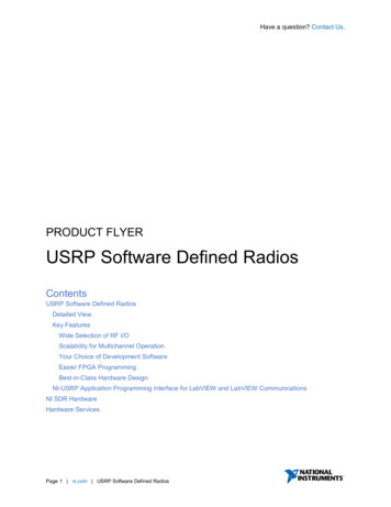
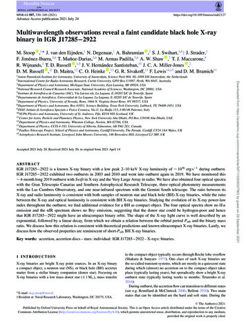
Caution Never touch the exposed pins of connectors.Note Do not install a device if it appears damaged in any way.3.Unpack any other items and documentation from the kit.Store the device in the antistatic package when the device is not in use.Verifying the Kit ContentsNI USRP-2920R1234561. NI 29xx Device2. AC/DC Power Supply and Power Cable3. Shielded Ethernet Cable4. SMA (m)-to-SMA (m) Cable5. 30 dB SMA Attenuator6. Getting Started Guide (This Document)Caution If you directly connect or cable a signal generator to your device, or ifyou connect multiple USRP devices together, you must connect a 30 dB attenuatorto the RF input (RX1 or RX2) of each receiving USRP device.Other Required ItemsIn addition to the kit contents, you must provide the following additional items: Computer with available gigabit Ethernet interface.Caution This product is not approved or licensed for transmission over the airusing an antenna. As a result, operating this product with an antenna may violatelocal laws. Ensure that you are in compliance with all local laws before operatingthis product with an antenna.NI USRP-2920/2921/2922 Getting Started Guide National Instruments 3
Optional Items LabVIEW Modulation Toolkit (MT), included on the driver software media, whichincludes MT VIs and functions, examples, and documentationNote You must install the LabVIEW Modulation Toolkit for proper operationof the NI-USRP Modulation Toolkit example VIs. LabVIEW Digital Filter Design Toolkit, included on the driver software mediaLabVIEW MathScript RT Module, included on the driver software mediaUSRP MIMO sync and data cable, available at ni.com, to synchronize clock sources Additional SMA (m)-to-SMA (m) cables to connect both channels with external devicesor to use the REF IN and PPS IN signalsGPS antenna for devices with GPS disciplined oscillator (GPSDO) support Preparing the EnvironmentEnsure that the environment you are using the USRP device in meets the followingspecifications.Operating temperature23 5 COperating humidity10% to 90% relative humidity, noncondensingPollution Degree2Maximum altitude2,000 mIndoor use only.Note Refer to the USRP device specifications at ni.com/manuals for completespecifications.Caution Do not operate the NI 292x in a manner not specified in this document.Product misuse can result in a hazard. You can compromise the safety protectionbuilt into the product if the product is damaged in any way. If the product isdamaged, return it to NI for repair.Installing the SoftwareYou must be an Administrator to install NI software on your computer.1. Install an ADE, such as LabVIEW.2.Visit ni.com/info and enter the Info Code usrpdriver to access the driver downloadpage for the latest NI-USRP software.3.Download the NI-USRP driver software.4 ni.com NI USRP-2920/2921/2922 Getting Started Guide
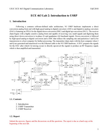
4.Follow the instructions in the installation prompts.Note Windows users may see access and security messages duringinstallation. Accept the prompts to complete the installation.5.When the installer completes, select Restart in the dialog box that prompts you to restart,shut down, or restart later.Installing NI 292x DevicesInstall all the software you plan to use before you install the hardware.1.Note The NI 292x device connects to a host computer using a standard gigabitEthernet interface. Refer to the documentation for your gigabit Ethernet interface forinstallation and configuration instructions.Power on the computer.2.Attach the antenna or cable to the front panel terminals of the NI 292x device as desired.3.Use the Ethernet cable to connect the NI 292x device to the computer. For maximumthroughput over Ethernet, NI recommends that you connect each NI 292x device to itsown dedicated gigabit Ethernet interface on the host computer.4.Connect the AC/DC power supply to the NI 292x device.5.Plug the power supply into a wall outlet. Windows automatically recognizes the NI 292xdevice.Synchronizing NI 292x Devices (Optional)You can connect two USRP devices so that they share clocks and the Ethernet connection tothe host.1. Connect the MIMO cable included with the kit to the MIMO EXPANSION port of eachdevice.NI USRP-292XNI USRP-292X2.If you have not already done so, attach antennas to the USRP devices.If you want to use one USRP device as a receiver and the other as a transmitter, attachone antenna to the RX 1 TX 1 port of the transmitter, and attach another antenna to theRX 2 port of the receiver.The NI-USRP driver ships with some examples that you can use to explore the MIMOconnection, including USRP EX Rx Multiple Synchronized Inputs (MIMO Expansion).vi andUSRP EX Tx Multiple Synchronized Outputs (MIMO Expansion).vi.NI USRP-2920/2921/2922 Getting Started Guide National Instruments 5
Configuring NI 292x DevicesSetting Up the Network (Ethernet Only)The device communicates with a host computer over gigabit Ethernet. Set up the network toenable communication with the device.Note The IP addresses for the host computer and each connected USRP devicemust be unique.Configuring the Host Ethernet Interface with a Static IP AddressThe default IP address for the NI 292x is 192.168.10.2.1. Ensure the host computer uses a static IP address.You may need to modify the network settings for the local area connection using theControl Panel on the host computer. Specify the static IP address in the Properties pagefor Internet Protocol Version 4 (TCP/IPv4).2.Configure the host Ethernet interface with a static IP address on the same subnet as theconnected device to enable communication, as shown in the following table.Table 1. Static IP AddressesComponentAddressHost Ethernet interface static IP address192.168.10.1Host Ethernet interface subnet mask255.255.255.0Default USRP device IP address192.168.10.2Note NI-USRP uses user datagram protocol (UDP) broadcast packets tolocate the device. On some systems, the firewall blocks UDP broadcast packets.NI recommends that you change or disable the firewall settings to allowcommunication with the device.Changing the IP AddressTo change the USRP device IP address, you must know the current address of the device, andyou must configure the network.1. Verify that your device is powered on and connected to your computer using the gigabitEthernet interface.2.Select Start»All Programs»National Instruments»NI-USRP»NI-USRPConfiguration Utility to open the NI-USRP Configuration Utility.3.Select the Devices tab of the utility.Your device should appear in the list on the left side of the tab.4.In the list, select the device for which you want to change the IP address.If you have multiple devices, verify that you selected the correct device.6 ni.com NI USRP-2920/2921/2922 Getting Started Guide
The IP address of the selected device displays in the Selected IP Address textbox.5.Enter the new IP address for the device in the New IP Address textbox.6.Click the Change IP Address button or press Enter to change the IP address.7.The utility prompts you to confirm your selection. Click OK if your selection is correct;otherwise, click Cancel.8.The utility displays a confirmation to indicate the process is complete. Click OK.9.Power cycle the device to apply the changes.The IP address of the selected device displays in the Selected IP Address textbox.10. After you change the IP address, you must power cycle the device and click RefreshDevices List in the utility to update the list of devices.Confirming Network Connection1.Select Start»All Programs»National Instruments»NI-USRP»NI-USRPConfiguration Utility to open the NI-USRP Configuration Utility.2.Select the Devices tab of the utility.Your device should appear in the list on the left side of the tab.Note If your device is not listed, verify that your device is powered on andcorrectly connected, then click the Refresh Devices List button to scan forUSRP devices.Configuring Multiple Devices with EthernetYou can connect multiple devices in the following ways: Multiple Ethernet interfaces—One device for each interface Single Ethernet interface—One device connected to the interface, with additional devicesconnected using an optional MIMO cable Single Ethernet interface—Multiple devices connected to an unmanaged switchTip Sharing a single gigabit Ethernet interface among devices may reduce overallsignal throughput. For maximum signal throughput, NI recommends that youconnect no more than one device per Ethernet interface.Multiple Ethernet InterfacesTo configure multiple devices connected to separate gigabit Ethernet interfaces, assigneach Ethernet interface a separate subnet, and assign the corresponding device an addressin that subnet, as shown in the following table.Table 2. Multiple Host Ethernet Interface ConfigurationDeviceHost IP AddressHost Subnet MaskDevice IP AddressUSRP Device 0192.168.10.1255.255.255.0192.168.10.2USRP Device 1192.168.11.1255.255.255.0192.168.11.2NI USRP-2920/2921/2922 Getting Started Guide National Instruments 7
Single Ethernet Interface—One DeviceYou can configure multiple devices using a single host Ethernet interface when the devices areconnected to each other using a MIMO cable.1. Assign each device a separate IP address in the subnet of the host Ethernet interface, asshown in the following table.Table 3. Single Host Ethernet Interface—MIMO ConfigurationDeviceHost IP AddressHost Subnet MaskDevice IP AddressUSRP Device 0192.168.10.1255.255.255.0192.168.10.2USRP Device 1192.168.10.1255.255.255.0192.168.10.32.Connect Device 0 to the Ethernet interface and connect Device 1 to Device 0 using aMIMO cable.Single Ethernet Interface—Multiple Devices Connected to an UnmanagedSwitchYou can connect multiple USRP devices to a host computer through an unmanaged gigabitEthernet switch that allows a single gigabit Ethernet adapter on the computer to interface withmultiple USRP devices connected to the switch.Assign the host Ethernet interface a subnet, and assign each device an address in thatsubnet, as shown in the following table.Table 4. Single Host Ethernet Interface—Unmanaged Switch ConfigurationDeviceHost IP AddressHost Subnet MaskDevice IP AddressUSRP Device 0192.168.10.1255.255.255.0192.168.10.2USRP Device 1192.168.10.1255.255.255.0192.168.10.3Programming the NI 292xYou can use the NI-USRP instrument driver to create communications applications for theNI 292x.NI-USRP Instrument DriverNI-USRP features a set of VIs and properties that exercise the functionality of the NI 292x,including configuration, control, and other device-specific functions. Refer to theNI-USRP Help for information about using the instrument driver in your applications.NI-USRP ExamplesThe instrument driver examples are instructional tools that demonstrate some of thefunctionality of the NI 292x. You can use these examples separately or integrate them intoyour systems. NI-USRP includes examples for getting started and other SDR functionality.You can access the NI-USRP examples from the following locations:8 ni.com NI USRP-2920/2921/2922 Getting Started Guide
From the Start menu at Start»All Programs»National Instruments»NI-USRP»Examples.In LabVIEW from Functions»Instrument I/O»Instrument Drivers»NI‑USRP»Examples palette.You can access additional examples from the code sharing community at ni.com/usrp.Note The NI Example Finder does not include NI-USRP examples.Testing the Device (Optional)Perform a loopback test to confirm that the device transmits and receives signals and isconnected correctly to the host computer.1. Attach the included 30 dB attenuator to one end of the SMA (m)-to-SMA (m) cable.2.Connect the 30 dB attenuator to the RX 2 TX 2 connector on the front panel of the USRPdevice, and connect the other end of the SMA (m)-to-SMA (m) cable to the RX 1 TX 1port.3.On the host computer, open the niUSRP EX Tx Continuous Async example VI and run it.If the device is transmitting signals, the IQ graph displays I and Q waveforms.4.Open the niUSRP EX Rx Continuous Async example VI and run it.If the device is receiving signals, the IQ graph displays I and Q waveforms.TroubleshootingIf an issue persists after you complete a troubleshooting procedure, contact NI technicalsupport or visit ni.com/support.Device TroubleshootingShould I Update Device Firmware and FPGA Images?NI 292x devices ship with firmware and FPGA images compatible with NI-USRP driversoftware. You may need to update the device for compatibility with the latest version of thesoftware.When you use the NI-USRP API, a default FPGA loads from persistent storage on the device.The driver software media also includes the NI-USRP Configuration Utility, which you canuse to update the devices.Updating NI 292x Firmware and FPGA Images (Optional)The firmware and FPGA images for NI 292x devices are stored in the device internal memory.You can reload the FPGA image or firmware image using the NI-USRP Configuration Utilityand an Ethernet connection, but you cannot create custom FPGA images using the Ethernetconnection.NI USRP-2920/2921/2922 Getting Started Guide National Instruments 9
1.If you have not already done so, connect the host computer to the device using theEthernet port.2.Select Start»All Programs»National Instruments»NI-USRP»NI-USRPConfiguration Utility to open the NI-USRP Configuration Utility.3.Select the N2xx/NI-29xx Image Updater tab. The utility automatically populates theFirmware Image and FPGA Image fields with the paths to the default firmware andFPGA image files. If you want to use different files, click the Browse button next to thefile you want to change, and navigate to the file you want to use.4.Verify that the firmware and FPGA image paths are entered correctly.5.Click the Refresh Device List button to scan for USRP devices and update the devicelist.If your device does not appear in the list, verify that the device is on and is correctlyconnected to the computer.If your device still does not appear in the list, you can manually add the device to the list.Click the Manually Add Device button, enter the IP address of the device in the dialogbox that displays, and click OK.6.Select the device to update from the device list, and verify that you selected the correctdevice.7.Verify that the version of the FPGA image file matches the board revision for the deviceyou are updating.8.To update the device, click the WRITE IMAGES button.9.A confirmation dialog box displays. Confirm your selections and click OK to continue.A progress bar indicates the status of the update.10. When the update completes, a dialog box prompts you to reset the device. A device resetapplies the new images to the device. Click OK to reset the device.Note The utility is unresponsive while it verifies that the device resetcorrectly.11. Close the utility.Related InformationRefer to the Load the images onto the on-board flash (USRP-N Series only) section of theUHD - USRP2 and N Series Application NotesWhy Doesn't the USRP Device Appear in MAX?MAX does not support NI 292x devices. Use the NI-USRP Configuration Utility instead.Open the NI-USRP Configuration Utility from the Start menu at Start»All Programs»National Instruments»NI-USRP»NI-USRP Configuration Utility.10 ni.com NI USRP-2920/2921/2922 Getting Started Guide
Why Doesn't the Device Power On?Check the power supply by substituting a different adapter.Why Doesn't the USRP Device Appear in the NI-USRPConfiguration Utility?1.Check the connection between the USRP device and the computer.2.Ensure that the USRP device is connected to a computer with a gigabit-compatibleEthernet adapter.3.Ensure that a static IP address of 192.168.10.1 is assigned to the adapter in yourcomputer.4.Allow up to 15 seconds for the device to completely start up.In the NI-USRP Configuration Utility, Why Does USRP2 AppearInstead of NI 292x?An incorrect IP address on the computer may cause this error. Check the IP address and runthe NI-USRP Configuration Utility again.An old FPGA or firmware image on the device may also cause this error. Upgrade the FPGAand firmware using the NI-USRP Configuration Utility.Why Don't NI-USRP Examples Appear in theNI Example Finder?NI-USRP does not install examples into the NI Example Finder.You can access the NI-USRP examples from the following locations: From the Start menu at Start»All Programs»National Instruments»NI-USRP»Examples. In LabVIEW from Functions»Instrument I/O»Instrument Drivers»NI‑USRP»Examples palette.Network TroubleshootingWhy Doesn't the Device Respond to a Ping(ICMP Echo Request)?The device should reply to an internet control message protocol (ICMP) echo request. To pingthe device, open a Windows command prompt and enter ping 192.168.10.2, where192.168.10.2 is the IP address for your USRP device. If you do not receive a response,verify that the host network interface card is set to a static IP address corresponding to thesame subnet as the IP address of the corresponding device. Also verify that the device IPaddress is set properly.Related InformationChanging the IP Address on page 6NI USRP-2920/2921/2922 Getting Started Guide National Instruments 11
Why Doesn't the NI-USRP Configuration Utility Return a Listingfor My Device?If the NI-USRP Configuration Utility does not return a listing for your device, search for aspecific IP address.1. Navigate to Program Files \National Instruments\NI-USRP\.2. Shift -right-click the utilities folder, and select Open command window herefrom the shortcut menu to open a Windows command prompt.3.Enter uhd find devices --args addr 192.168.10.2 in the command prompt,where 192.168.10.2 is the IP address for your USRP device.4.Press Enter .If the uhd find devices command does not return the listing for your device, thefirewall may be blocking replies to UDP broadcast packets. Windows installs and enablesa firewall by default. To allow UDP communication with a device, disable any firewallsoftware associated with the network interface for the device.Why Doesn't the Device IP Address Reset to the Default?If you cannot reset the default device IP address, your device may be on a different subnet thanthe host network adapter. You can power cycle the device in a safe (read-only) image, whichsets the device to the default IP address of 192.168.10.2.1. Open the device enclosure, making sure to take appropriate static precautions.2.Locate the safe-mode button, a push-button switch (S2), inside the enclosure.3.Press and hold the safe-mode button while you power cycle the device.4.Continue to press the safe-mode button until the front panel LEDs blink and remain solid.5.While in safe-mode, run the NI-USRP Configuration Utility to change the IP addressfrom the default, 192.168.10.2, to a new value.6.Power cycle the device without holding the safe-mode button to return the normal mode.Note NI recommends that you use a dedicated network with no other USRPdevices connected to the host computer to avoid the possibility of an IP addressconflict. Also, verify that the static IP address of the host network adapter onthe computer that runs the NI-USRP Configuration Utility is different from thedevice default IP address of 192.168.10.2 and different from the new IPaddress to which you want to set the device.Note If the device IP address is on a different subnet from the host networkadapter, the host system and configuration utility cannot communicate with andconfigure the device. For example, the utility recognizes, but cannot configure adevice with an IP address of 192.168.11.2 connected to a host networkadapter with a static IP address of 192.168.10.1 and a subnet mask of255.255.255.0. To communicate with and configure the device, change thehost network adapter to a static IP address on the same subnet as the device,12 ni.com NI USRP-2920/2921/2922 Getting Started Guide
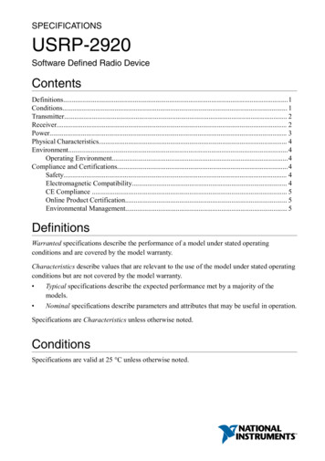
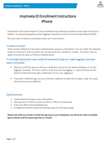
such as 192.168.11.1, or change the subnet mask of the host networkadapter to recognize a wider range of IP addresses, such as 255.255.0.0.Related InformationChanging the IP Address on page 6Why Does the Device Not Connect to the Host Interface?The host Ethernet interface must be a gigabit Ethernet interface to connect to the USRPdevice.Ensure the connection between the host network interface card and the device cableconnection is valid and both the device and computer are powered on.A lit green LED in the upper left corner of the gigabit Ethernet connection port on thedevice front panel indicates a gigabit Ethernet connection.Front Panels and ConnectorsDirect Connections to the NI 292xThe NI 292x is a precision RF instrument that is sensitive to ESD and transients. Ensure youtake the following precautions when making direct connections to the NI 292x to avoiddamaging the device.Caution Apply external signals only while the NI 292x is powered on. Applying external signals while the device is powered off may cause damage.Ensure you are properly grounded when manipulating cables or antennas connected to theNI 292x TX 1 RX 1 or RX 2 connector.If you are using noninsulated devices, such as a noninsulated RF antenna, ensure thedevices are maintained in a static-free environment.If you are using an active device, such as a preamplifier or switch routed to the NI 292xTX 1 RX 1 or RX 2 connector, ensure that there are no signal transients greater than theRF and DC specifications for the device that are being generated and sourced to theNI 292x TX 1 RX 1 or RX 2 connector.NI USRP-2920Figure 1. NI USRP-2920 Front PanelRX 1TX 1NI USRP-2920RX 250 MHz - 2.2 GHz6VACEREF INPPS INMIMO EXPANSION3ABDFGB ETHERNETNI USRP-2920/2921/2922 Getting Started Guide POWER National Instruments 13
Table 5. NI USRP-2920 Module Front Panel ConnectorsConnectorRX 1UseInput and output terminal for the RF signal. RX 1 TX 1 is an SMA (f)connector with an impedance of 50 Ω and is a single-ended input oroutput channel.TX 1RX 2Input terminal for the RF signal. RX 2 is an SMA (f) connector withan impedance of 50 Ω and is a single-ended input channel.REF INInput terminal for an external reference signal for the local oscillator(LO) on the device. REF IN is an SMA (f) connector with animpedance of 50 Ω and is a single-ended reference input. REF INaccepts a 10 MHz signal with a minimum input power of 0 dBm(.632 Vpk-pk) and a maximum input power of 15 dBm (3.56 Vpk-pk)for a square wave or sine wave.PPS INInput terminal for the pulse per second (PPS) timing reference.PPS IN is an SMA (f) connector with an impedance of 50 Ω and is asingle-ended input. PPS IN accepts 0 V to 3.3 V TTL and 0 V to 5 VTTL signals.MIMOEXPANSIONThe MIMO EXPANSION interface port connects two USRP devicesusing a compatible MIMO cable.GB ETHERNETThe gigabit Ethernet port accepts an RJ-45 connector and gigabitEthernet compatible cable (Category 5, Category 5e, or Category 6).POWERThe power input accepts a 6 V, 3 A external DC power connector.Table 6. NI USRP-2920 Module LEDsLEDIndicationAIndicates the transmit status of the module:OFF—The module is not transmitting data.GREEN—The module is transmitting data.BIndicates the status of the physical MIMO cable link:OFF—The modules are not connected using the MIMO cable.GREEN—The modules are connected using the MIMO cable.14 ni.com NI USRP-2920/2921/2922 Getting Started Guide
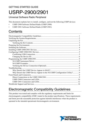
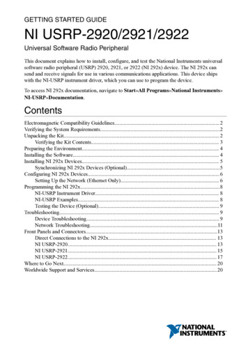
Table 6. NI USRP-2920 Module LEDs (Continued)LEDIndicationCIndicates the receive status of the module:OFF—The module is not receiving data.GREEN—The module is receiving data.DIndicates the firmware status of the module:OFF—The firmware is not loaded.GREEN—The firmware is loaded.EIndicates the reference lock status of the LO on the module:OFF—There is no reference signal, or the LO is not locked to a reference signal.BLINKING—The LO is not locked to a reference signal.GREEN—The LO is locked to a reference signal.FIndicates the power status of the module:OFF—The module is powered off.GREEN—The module is powered on.NI USRP-2921Figure 2. NI USRP-2921 Front PanelRX 1TX 1NI USRP-2921RX 2TX 22.4 - 2.5 GHz, 4.9 - 5.85 GHz6VREF INPPS INMIMO EXPANSIONABCDEFGB ETHERNET3APOWERTable 7. NI USRP-2921 Module Front Panel ConnectorsConnectorRX 1TX 1RX 2UseInput and output terminal for the RF signal. RX 1 TX 1 is an SMA (f)connector with an imped
This document explains how to install, configure, and test the National Instruments universal software radio peripheral (USRP) 2920, 2921, or 2922 (NI 292x) device. The NI 292x can send and receive signals for use in various communications applications. This device ships with the NI-USRP instrument driver, which you can use to program the device.