Transcription
All Sport 100Control ConsoleOperations ManualED-13432Rev 3 – 10 October 2007
ED13432Product 1196Rev 3 – 10 October 2007DAKTRONICS, INC.Copyright 2003-07All rights reserved. While every precaution has been taken in the preparation of this manual, the publisherassumes no responsibility for errors or omissions. No part of this book covered by the copyrights hereon may bereproduced or copied in any form or by any means – graphic, electronic, or mechanical, including photocopying,taping, or information storage and retrieval systems – without written permission of the publisher. All-Sport is a trademark of Daktronics, Inc
Table of ContentsSection 1:Introduction. 11.11.2How To Use This Manual.1Daktronics Nomenclature .3Section 2:Controller Overview . 52.12.22.32.4All Sport 100 Overview .5Display Connection.6Replacement Parts List .6Daktronics Exchange and Repair and Return Programs .6Exchange Program.6Before Contacting Daktronics .7Repair & Return Program .8Shipping Address.8Section 3:Basic Operation . 93.13.23.33.43.5Console Operation .9All Sport 100 Inserts and Codes .9Sport Insert Operation Concepts .10Startup.10Common Sport Keys.11Start.11Stop.11Enter/Edit.11Clear/Alt .11Set Time.11Count Up/Down.12Auto Horn .12Manual Horn.13Dimming.13Section 4:Clock/Score Operation. 154.1Clock Keys.15Set Time.15Period 1.16Score Keys .17Home/Guest Score Keys.17Bonus Keys.17Possession Key .184.2Table of Contentsi
Section 5:Segment Timer Operation. 195.15.2Segment Timer Information.19Segment Timer Keys.20Main Screen .20First/Last Segment .20Segment Number/Time.20Set Program .21Interval Time.21Copy Range .22Auto Stop .22Warning Time .22Reset Current Segment .23Edit Current Segment.23Reset to First Segment .23TI-2025/2026 Segment Timer.23Send Program Information to Display .23TI-2025/2026 Play Clock (Segment Timer Program 6).24TI-2025/2026 Two-Minute Drill (Segment Timer Program 7).24RC-50 Segment Timer .25Controls (Programs 1-5) .25RC-50 Play Clock Controls (Program 6) .25RC-50 Two-Minute Drill Controls (Program 7) .25Section 6:Baseball Operation. 276.1Baseball Keys.27Out 1, Inning 1.27Ball, Strike, Clear Ball/Strike .28Hit, Error.28Home/Guest Score 1, -1.28Appendix A: Reference Drawings . 29iiIntroduction
Section 1: Introduction1.1How To Use This ManualImportant Safeguards:Read and understand these instructions before installing the display.Do not drop the control console or allow it to get wet.Properly ground the scoreboard with a grounding electrode at the scoreboardlocation.Disconnect power when the scoreboard is not in use.Disconnect power when servicing the scoreboard.Do not modify the scoreboard structure or attach any panels or coverings to thescoreboard without the express written consent of Daktronics, Inc.1.2.3.4.5.6.Figure 1 illustrates theDaktronics drawingnumbering system.Daktronics identifiesindividual engineeringdrawings by their drawingnumber (7087-P08A-69945in the example), which islocated in the lower rightcorner of the drawing. ThisFigure 1: Daktronics Drawing Labelmanual refers to drawings by their last set of numbers and the letter preceding them. Theexample would be Drawing A-69945.Reference drawings are grouped and inserted in alphanumeric order in the Appendix.Listed below are a number of drawing types commonly used by Daktronics, along with theinformation that each is likely to provide. IntroductionSystem riser diagrams: overall system layout from control room to display,power and phase requirementsShop drawings: fan locations, transformer locations, mounting information,power and signal entrance points and access method (Front or rear)Schematics: power wiring, signal wiring, panelboard or power terminationpanel assignments, signal termination panel assignments and transformerassignmentsFinal assembly: component locations, part numbers, display dimensions andassembly/disassembly instructions1
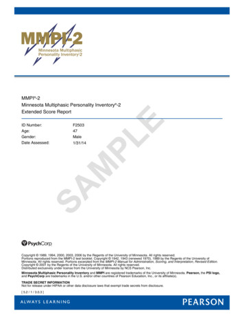
All references to drawing numbers, appendices, figures, or other manuals are presented inbold typeface, as in this example: “Refer to Drawing A-66945 for the location of the driverenclosure.” Additionally, any drawings referenced within a particular subsection are listed atthe beginning of that subsection in the following manner:Reference Drawing:Segmentation, 7 Seg Bar Digit . Drawing A-69945Daktronics identifies manuals by their engineering document (ED) number, which is locatedon the cover page of the manual. For example, this manual would be referred to as ED-13432.The serial and model numbers of a Daktronics scoreboard can be found on the ID label on thedisplay. The label will be similar to the one shown in Figure 2. When calling DaktronicsCustomer Call Center, please have this information available to ensure quick service. Forfuture reference, note the scoreboard model number serial number, and installation date onthe second page of this manual.Figure 2: Scoreboard ID LabelDaktronics displays are built for long life and require little maintenance. However, from timeto time, certain display components will have to be replaced. The Replacement Parts List inSection 2.3 provides the names and part numbers of components that may require replacementduring the life of this display.Following the Replacement Parts List is an explanation of Daktronics Exchange and Repair andRepair Programs. Refer to these instructions if replacement components or repair is needed.2Introduction
1.2Daktronics NomenclatureTo fully understand some Daktronics drawings, such as schematics, it is necessary to knowhow various components are labeled in those drawings. This information is useful whentrying to communicate maintenance or troubleshooting efforts.The label “A” on a drawing item typically denotes an assembly. An assembly can be a singlecircuit board or a collection of components that function together, usually mounted on asingle plate or in a single enclosure.In addition, the following labeling formats might be found on various Daktronics drawings: “TB ” denotes a termination block for power or signal cable.“F ” denotes a fuse.“E ” denotes a grounding point.“J ” denotes a power or signal jack.“P ” denotes a power or signal plug for the opposite jack.Finally, Daktronics part numbers are commonly found on drawings. Those part numbers canbe used when requesting replacement parts from Daktronics Customer Call Center. Takenote of the following part number formats. (Not all possible formats are listed here). “0P- - ” denotes an individual circuit board, such as a driver board.“0A- - ” denotes an assembly, such as a circuit board and the plate or bracketto which it is mounted. A collection of circuit boards working as a single unit may alsocarry an assembly label.“W- ” denotes a wire or cable. Cables may also carry the assembly numberingformat in certain circumstances. This is especially true for ribbon cables.“F- ” denotes a fuse.“T- ” denotes a transformer.“PR- - ” denotes a specially ordered part.“M- ” denotes a metal part, and “0M- ” typically denotes a fabricatedmetal assembly.Introduction3
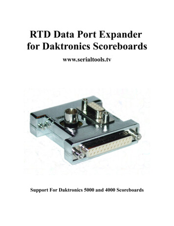
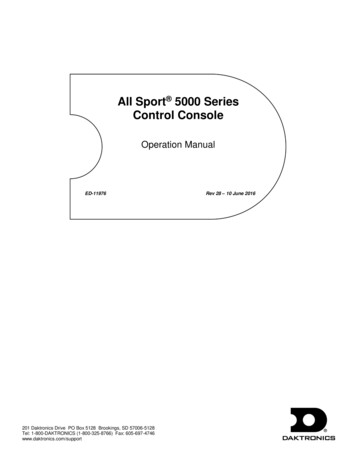
Section 2:Controller OverviewSection 2 includes the following subsections:All Sport 100 Overview: identifies the control equipment and how it operates the displaysReplacement Parts List: includes the components of the All Sport 100 that may need to be replacedDaktronics Exchange and Repair and Return Programs: covers the procedure for returningequipment to Daktronics and/or requesting new parts2.1All Sport 100 OverviewThe All Sport 100 Series controller, shown in Figure 3, is ahand-held controller designed to operate Daktronics BB-114portable basketball scoreboard. This lightweight, 6" high by4 1/4" wide controller is encased in ABS plastic, making it adurable as well as convenient control option. The console’sliquid crystal display (LCD) will guide you through theoperation of the system.The All Sport 100, identified by the series number AS-100,can be configured to display game time, game scores andpossession and bonus information. For details onconfiguring the All Sport 100 to operate a display, refer toSection 3: Basic Operation.When opening the packages, inspect for shipping damagesuch as rattles and dents. See that all equipment is includedas shown on the packing slip. Immediately report anydeficiencies to Daktronics. Save all packing materials forshipping if warranty repair or exchange is needed.Controller OverviewFigure 3: All Sport 1005
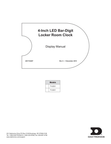
2.2Display ConnectionA 2-pair, shielded cable at 22 AWGconnects the All Sport 100 controller toDaktronics BB-114 portable basketballscoreboards.The cable extends from the XLR jack atthe rear of the BB-114 to the 9-pin jack onthe top of the controller, as shown inFigure 4.For more information regarding the BBFigure 4: Display Connection114 portable basketball display, refer toED-13315, the BB-114 Portable LEDBasketball Scoreboard Installation, Maintenance, and Operation Manual.2.3Replacement Parts ListThe following is a list of possiblereplacement parts for the All Sport 100controller. When re-ordering a part, besure to use its corresponding partnumber.2.4PartPart NumberAll Sport 100 controllerCableClock/score insertSegment timer insertWall pack -1118Daktronics Exchange and Repair and Return ProgramsTo serve customers’ repair and maintenance needs, Daktronics offers both an ExchangeProgram and a Repair and Return Program.Exchange ProgramDaktronics unique Exchange Program is a quick service for replacing key parts in need ofrepair. If a part requires repair or replacement, Daktronics sends the customer a replacement,and the customer sends the defective part to Daktronics. This decreases display downtime.6Controller Overview
Before Contacting DaktronicsIdentify these important part numbers:Display Serial Number:Display Model Number:Contract Number:Date Installed:Location of Sign (Mile Marker Number):Daktronics Customer ID Number:To participate in the Exchange Program, follow these steps.1.Call Daktronics Customer Service:Market DescriptionSchools (primary through community/juniorcolleges), religious organizations, municipal clubsand community centersUniversities and professional sporting events, liveevents for auditoriums and arenasFinancial institutions, petroleum, sign companies,gaming, wholesale/retail establishmentsDepartment of Transportation, mass transits,airports, parking facilities2.Customer Service 3157When the new exchange part is received, mail the old part to Daktronics.If the replacement part fixes the problem, send in the problem part which is beingreplaced.a.Package the old part in the same shipping materials in which the replacementpart arrived.b. Fill out and attach the enclosed UPS shipping document.c. Ship the part to Daktronics.3.A charge will be made for the replacement part immediately, unless a qualifyingservice agreement is in place.In most circumstances, the replacement part will be invoiced at the time it is shipped.4.If the replacement part does not solve the problem, return the part within 30working days or the full purchase price will be charged.If, after the exchange is made the equipment is still defective, please contactCustomer Service immediately. Daktronics expects immediate return of an exchangepart if it does not solve the problem. The company also reserves the right to refuseparts that have been damaged due to acts of nature or causes other than normal wearand tear.Controller Overview7
Repair & Return ProgramFor items not subject to exchange, Daktronics offers a Repair & Return Program. To send apart for repair, follow these steps:1.Call or fax Daktronics Customer Service:Refer to the appropriate market number in the chart listed on the previous page.Fax: 605-697-44442.Receive a Return Material Authorization (RMA) number before shipping.This expedites repair of the part.3.Package and pad the item carefully to prevent damage during shipment.Electronic components, such as printed circuit boards, should be placed in anantistatic bag before boxing. Daktronics does not recommend Styrofoam peanuts inpackaging.4.Enclose: your name address phone number the RMA number should be written clearly on the outside of the box a clear description of symptomsShipping AddressDaktronics Customer ServicePO Box 5128331 32nd AveBrookings, SD 570068Controller Overview
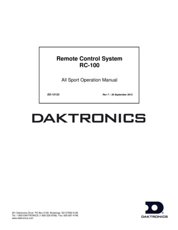
Section 3:3.1Basic OperationConsole OperationThe console face consists of a two-line-by-16-character liquid crystal display and a sportspecific keyboard insert. In most cases, the top line of the LCD shows the main clock time, thedirection the clock is counting and when the main horn is sounding. Generally, the bottomline of the LCD displays the home and guest team scores.Throughout this manual, the names or letters of keys on the keyboard are enclosed in anglebrackets (such as ENTER* ). Keys and functions common to all sports are explained inSection 3.5. All of the keys that pertain to a specific sport code insert are explained in detailin the section of the manual for that specific sport.3.2All Sport 100 Inserts and CodesReference Drawings:Insert; A/S 100 Clock/Score Code-01 . Drawing A-167854Insert; A/S 100 Insert; Baseball . Drawing A-184219Insert; LL-2648 Segment Timer Code-06 . Drawing A-274996Sport inserts are used to allow a single console to control multiple sports. Select the properinsert from the chart below and slide it into the insert opening, on the left side of the console,until it stops. To remove a sport insert, pull on the tab that extends from the left side of theconsole. The insert will easily slide out.The All Sport 100 uses two different keypadinserts to program game time,segment/practice timing, game score andbonus and possession information intoDaktronics BB-114 portable basketball displays.Segment timing is controlled by sport insertLL-2648, and all other data is entered usingsport insert LL-2550.Figure 5 at right illustrates one AS-100 insertused to control the displays. For more detailson the inserts, refer to the All Sport 100 insertdrawings, Drawings A-167854, and A-274996,located in Appendix A: Reference Drawings.If an insert is lost or damaged, a copy of theinsert drawings are located in Appendix A:Reference Drawings can be used until areplacement is ordered.Basic OperationsFigure 5: All Sport 100 Insert LL-26489
The All Sport 100 controls the Daktronics BB-144 portable basketball displays. Operation ofthe displays is discussed in Section 3, Section 4, and Section 5 of this manual. To start up thecontroller and use the insert, refer to Section 3. Read the section carefully to fully understandthe operation instructions.3.3Sport Insert Operation ConceptsA sport insert identifies keys used in the normal course of operation for a specific sport. Inmost cases, pressing a key immediately changes the scoreboard. Sometimes a sequence ofkeys must be pressed before a change takes place on the scoreboard. Keys that require entryof additional information are marked with a dot, for example, SETx . The additionalinformation required usually is a number followed by the ENTER* key.Some keys also include a 1. Pressing one of these keys once increments, or increases, by onethe corresponding field on the scoreboard (such as team score or period). A key with -1decrements, or decreases, the total of a scoreboard field by one.On most inserts, certain keys have been grouped together under the headings Home orGuest. These keys are Team keys, and they work the same for both teams. They affect thestatistics only for the specific home or guest team. Keys not under one of these headings areGame keys. They are general keys for the progress of the game, such as period or quarter.Other keys have been blocked together to emphasize that these keys work together.3.4StartupLCD DisplayALL SPORT 100ED-13375 ver 1.0ActionThe console performs a self-test when it is powered on. During theself-test, a message displays the standard software loaded in theconsole.ED standard software numberENTER CODE 01clock/scoreWhen the self-test completes, the screen displays the last codeentered into controller.To select a new sport code:1.2.3.10Press CLEAR to clear the previous code.Get the code number from the sport insert or the section of themanual for that sport.Use the number keys to enter the new two-digit code. Press ENTER* .Basic Operations
3.5Common Sport KeysStart START is used to start the main clockStop STOP is used to stop the main clock.Enter/EditThe ENTER*/EDIT key has dual functions. This key functions as the enter key whenediting game data. Pressing the key will accept the new data and end the edit. If not in Editmode, the ENTER*/EDIT key allows the user to select the item to be edited, such as teamscore. After pressing the ENTER*/EDIT key, the operator presses one of the increment ordecrement keys for the desired field on the scoreboard. The operator then simply enters thevalue he or she wishes to display and presses ENTER*/EDIT to accept it.Clear/AltThe CLEAR/ALT key has also two functions. The key operates as the clear key whenediting game data. Pressing the key will clear the data being edited, or, if pressed twice, willexit the edit. When not in Edit mode the CLEAR/ALT key allows the user to access thealternate function keys. Pressing the CLEAR/ALT and then one of the alternate functionkeys will initiate the desired function.Set TimeLCD Displaytime editsetcurrmm:ss.tmm:ss.t minutes, seconds,tenths of a secondActionAfter the main clock has been stopped, press SET TIMEx todisplay the current time of the main clock.To change the time, enter the desired time on the number pad andpress ENTER* .Press CLEAR twice to clear changes and return to the game.Basic Operations11
Count Up/DownLCD DisplayActionMAIN CLOCK-DOWN v1-UP, 2-DOWNAfter the main clock has been stopped, the direction of the clock canbe set.Up/down current directionPress ALT , and press SET TIME to move to the main clockmenu.Press 1 or 2 to select Up or Down (default).Notes: The current direction of the main clock is shown on the topline of the LCD with an up (u) arrow to show count up and a down (v)arrow to show count down.The COUNT UP/DOWNx function is disabled while the clock isrunning.Auto HornLCD DisplayAUTO HORN-ON1-ON, 2-OFFActionuhon/off current settingTo get to the Auto Horn menu, press ALT , and then press AUTOHORN .h appears on the upper right corner of the LCD when the Auto Hornis enabled. An up/down (uv) arrow also appears to indicate clockdirection.Press 1 or 2 to select On (default) or Off.12Basic Operations
Manual HornPress MANUAL HORN to sound the main horn. The horn sounds as long as the key ispressed. The horn stops sounding when the key is released.DimmingLCD DisplayDimmingLevel (0-3): noneActionPress 0 , 1 , 2 or 3 to select the intensity for the digits on thescoreboard. Press ENTER* to accept the new dimming level. 0 none (bright) 1 2/3 (dim) 2 1/2 (dimmer) 3 1/3 (dimmest)13Basic Operations
Section 4:Clock/Score OperationReference Drawing:Insert; A/S 100 Clock/Score Code-01 . Drawing A-167854The All Sport 100 controller enters Clock/Scoreinformation into Daktronics BB-114 portablescoreboards using sport insert LL-2550, shown at rightin Figure 6. If this insert is lost or damaged, a copy ofthe insert drawing, Drawing A-167854, can be useduntil a replacement can be ordered.Refer Section 3 for information on starting the consoleand for instructions for use of the sport insert. Read theBasic Operation material carefully to fully understandthe following operating instructions.This section provides instructions for using the AllSport 100 controller to program game time and gamescore into Daktronics BB-114 displays. To run theClock/Score insert for the BB-114 scoreboard, enterCode 01 at the Enter Code command.4.1Figure 6: Clock/Score Insert LL-2550Clock KeysSet TimeThe current time on the main clock is displayed by pressing SET TIMEx and it can bechanged by entering the desired time on the number pad and pressing ENTER* . Thedefault period length can be edited by pressing SET TIMEx a second time.LCD Displaytime editsetcurr mm:ss.t*mm:ss.T minutes, seconds,tenths of a secondTo display the current clock time, press SET TIMEx .To change the current clock time, enter the new time in minutes andseconds on the number pad and press ENTER* .Press CLEAR twice to clear changes and return to the game.Clock/Score Operations15
LCD DisplayTime editeditPeriod mm:ss.t*mm:ss.T minutes, seconds,tenths of a secondActionTo display the configured time for period length, press SETTIMEx twice.To accept the period length as the new clock time, press ENTER* . To decline the selection of the period length,press CLEAR .To change the period length and set the main clock, enter thenew time in minutes and seconds using the number pad andpress ENTER* .Press CLEAR twice to clear changes and return to thegame.Period 1LCD DisplayPeriod:edit 2ActionPress PERIOD 1 to increment the total.The LCD shows which key was pressed and the new value.To edit the period, press the ENTER*/EDIT key followed by PERIOD 1 and then enter the desired number on the keypad. Press ENTER*/EDIT to accept the number.16Clock/Score Operations
4.2Score KeysThis section discusses the All Sport 100 controller keys used to input game score, bonus, andpossession information into the BB-114 portable basketball scoreboard.Home/Guest Score KeysThese scoring keys allow the user to increment the game score by one or two points at a time.Refer to the tables on the following page for instructions on the use of the Home/Guest Scorekeys. The tables use home as an example, but the instructions are the same for both Homeand Guest.LCD DisplayTime mm:ss.th 0 g oActionhuThis screen shown at left is the default screen forthe Clock/Score All Sport insert. The initial gamescore for both teams is zero.MM minutes SS secondsT tenths of a secondHome score 11To add points to the home team score, press HOME SCORE 1 .This key changes the hometeam score by adding one point.Timeh 1The screen at right appears.:56.0g oHome score -10 HOME SCORE 2 operates similarly to the HOME SCORE 1 key, as it adds two points tothe home team score instead of one.To subtract points from the home team score, press HOME SCORE -1 . This key changes the score bysubtracting one point.Bonus KeysThese two keys on the All Sport 100 is used to program bonus and possession informationinto the BB-114 scoreboard. When either home Bonus or Guest Bonus is selected, thecontroller sends the signal to the scoreboard and the corresponding bonus indicatorilluminates. The table uses home as an example, but the instructions are the same for bothHome and Guest.Clock/Score Operations17
LCD DisplayHome bonusOnActionPressing the BONUS g key toggles bonus information on and off for thehome team.To program bonus f
Daktronics identifies manuals by their engineering document (ED) number, which is located on the cover page of the manual. For example, this manual would be referred to as ED-13432. The serial and model numbers of a Daktronics scoreboard can be found on the ID label on the display. The label will be similar to the one shown in Figure 2.