Transcription
Remote Control SystemRC-100All Sport Operation ManualED-15133201 Daktronics Drive PO Box 5128 Brookings, SD 57006-5128Tel: 1-800-DAKTRONICS (1-800-325-8766) Fax: 605-697-4746www.daktronics.comRev 7 – 26 September 2012
ED-15133Product 1110Rev 7 – 26 September 2012DAKTRONICS, INC.Copyright 2007-2012All rights reserved. While every precaution has been taken in the preparation of this manual, the publisherassumes no responsibility for errors or omissions. No part of this book covered by the copyrights hereon may bereproduced or copied in any form or by any means – graphic, electronic, or mechanical, including photocopying,taping, or information storage and retrieval systems – without written permission of the publisher.All Sport , DataTime , and OmniSport are trademarks of Daktronics, Inc. All other trademarks used in this manual are theproperty of their respective owners.
Table of ContentsSection 1:Introduction . 11.11.2Resources. 1Daktronics Exchange and Repair & Return Programs. 2Exchange Program . 2Before Contacting Daktronics . 2Repair & Return Program . 3Shipping Address . 3Daktronics Warranty and Limitation of Liability . 3Section 2:RC-100 System Overview . 5Section 3:RC-100 Base Station . 73.1Function Setting . 7Selecting Functions . 8All Sport Scoreboard Controller Function . 8Gen I Operation. 8Channel Setting . 9Synchronizing Multiple Base Stations and Channel Selection . 10Installations with a Central Base Station . 11Installations with Base Station Groups . 12Server/Client Mode Setting . 13Wireless Base Station LEDs . 14LED Error Diagnostics . 153.23.33.43.5Section 4:RC-100 Handheld Controller. 174.1Powering the Controller On and Off . 17Using the Keypad. 17Using External Power . 17Battery Operation . 17Idle Time . 17Battery Recharging. 17Operation Modes . 18Config Mode . 18Setting Default Radio Channel Number . 18Setting LCD Contrast . 18Setting Power Save Mode . 19Connect Mode . 19Switching to Connect Mode . 19Signal Strength Indicator . 20Common Keys . 20Alternate Function Keys . 214.24.34.44.5Section 5:All Sport Applications . 235.15.2Selecting All Sport Applications (Code Numbers) . 23Keypad Inserts . 24Keypad Insert Operation Concepts . 24Common All Sport Application Keys . 255.3Table of Contentsi
New Code (Alternate Function) . 25New Game (Alternate Function) . 25Start . 26Stop . 26Set Time . 26UP/DN (Alternate Function) . 26Dim (Alternate Function) . 27Manual Horn . 27Auto Horn . 28Section 6:Clock/Score Operation .296.1Clock Score Keys . 29Home/Guest Score 1, -1 . 29Period 1 . 29Set TOD (Alternate Function) . 29Section 7:Volleyball Operation .317.1Volleyball Keys . 31Home/Guest Score 1, -1 . 31Home/Guest Won 1, -1 . 31Reset Game Score . 32Game 1, -1 . 32Section 8:Baseball Operation .338.1Baseball Keys . 33Home/Guest Score 1, -1 . 33Out 1, Inning 1 . 33Ball, Strike, Clear Ball & Strike . 33Hit, Error . 34Time, At Bat, H/E (Alternate Function). 34Time/At Bat . 34Section 9:Play Clock & Pitch Timer Operation.359.1Play Clock & Pitch Timer Keys . 35Set Reset 1, Set Reset 2 . 35Reset 1, Reset 2 . 35Section 10:Segment Timer Operation .3710.110.2Segment Timer Information . 37Segment Timer Keys . 37First/Last Segment . 37Segment Number/Time . 38Interval Time . 38Copy Range . 39Auto Stop. 39Warning Time . 40Current Segment 1 . 40Reset Current Segment . 40Reset to First Segment . 40iiTable of Contents
Section 11:Tennis Operation . 4111.111.2Court Selection . 41Tennis Keys . 41Serve. 41Game 1 . 42Point . 42Reset Game . 42Tie Break . 42TOD/Game . 43Set 1. 43Reset Match (Alternate Function) . 43Matches Won (Alternate Function) . 43Next Match (Alternate Function – DakTennis Only) . 44Winner (Alternate Function – DakTennis Only) . 44Section 12:Basketball Operation . 4512.1Basketball Keys . 45Home/Guest Score 1, 2, ( 3, -1) . 45Fouls 1 . 45Possession . 46Period 1 . 46Set TOD (Alternate Function) . 461/10 SEC (Alternate Function) . 46Bonus (Alternate Function). 47Section 13:Football Operation . 4913.1Football Keys . 49Home/Guest Score 1, 6, ( 3, -1) . 49Ball On . 49Down 1 . 50TOL -1 . 50To Go . 50Possession (Alternate Function) . 50QTR 1 . 51Section 14:Remote Start/Stop Operation . 5314.1Remote Start/Stop Keys . 53Start . 53Stop . 53Manual Horn/Reset . 53Section 15:Goal Judge Operation . 5515.1Goal Judge Keys . 55Goal Light On/Off . 55Section 16:CAN Handheld Operation . 5716.116.2Common CAN Handheld Operation . 57Diving & Synchronized Swimming Operations . 57Table of Contentsiii
16.3Rodeo Operations. 57Section 17:Troubleshooting .5917.117.2Handheld Controller Error Messages . 59Base Station Errors . 60IN RANGE LED On Start-up. 60General Base Station Failures . 60Obtaining Base Station Status Information . 61Replacing Handheld Battery . 6117.3Appendix A:Reference Drawings.63Appendix B:Sport Inserts .65Appendix C:Daktronics Warranty and Limitation of Liability .67ivTable of Contents
Section 1:IntroductionThis manual is designed to explain the operation of the Daktronics RC-100 Remote Control Systemfor All Sport applications. For additional information regarding the safety, installation, operation, orservice of this system, refer to the telephone numbers listed in Section 1.2.Important Safeguards1.11.Read and understand all instructions, both general and for specific applications.2.Do not drop the control console or allow it to get wet.3.Do not disassemble control equipment or electronic controls of the display; failure tofollow this safeguard will make the warranty null and void.4.Always turn off and/or unplug the control equipment when it is not in use. Neveryank the power cord to pull the plug from the outlet. Grasp the plug and pull todisconnect.5.Do not let any power cord touch hot surfaces or hang over the edge of a table thatwould damage or cut the cord.6.If an extension cord is necessary, a three-pronged, polarized cord should be used.Arrange the cord with care so that it will not be tripped over or pulled out.7.Inspect console for shipping damage such as rattles and dents, and verify that allequipment is included as itemized on the packing slip. Immediately report anyproblems to Daktronics; save all packing materials if exchange is necessary.ResourcesFigure 1 illustrates a Daktronicsdrawing label. The drawing number islocated in the lower-right corner of adrawing. This manual refers todrawings by listing the last set ofdigits and the letter preceding them.In the example, the drawing would bereferred to as Drawing C-325405.Figure 1: Daktronics Drawing LabelReference Drawing:System Riser Diagram . Drawing C-325405Daktronics identifies manuals by an ED or DD number located on the cover page of eachmanual. For example, this manual would be referred to as ED-15133.Introduction1
1.2Daktronics Exchange and Repair & Return ProgramsExchange ProgramThe Daktronics Exchange Program is a service for quickly replacing key components in needof repair. If a component fails, Daktronics sends a replacement part to the customer who, inturn, returns the failed component to Daktronics. This decreases equipment downtime.Customers who follow the program guidelines explained below will receive this service.Before Contacting DaktronicsIdentify these important numbers:Assembly Number:Job/Contract Number:Date Installed:Daktronics Customer ID Number:To participate in the Exchange Program, follow these steps.1.Call Daktronics Customer Service.Market DescriptionCustomer Service NumberSchools (including community/junior colleges), religiousorganizations, municipal clubs and community centers877-605-1115Universities and professional sporting events, live eventsfor auditoriums and arenas866-343-60182.When the new exchange part is received, mail the old part to Daktronics.If the replacement part fixes the problem, send in the problem part being replaced.a. Package the old part in the same shipping materials in which the replacementpart arrived.b. Fill out and attach the enclosed UPS shipping document.c. Ship the part to Daktronics.3.The defective or unused parts must be returned to Daktronics within 5 weeks ofinitial order shipment.If any part is not returned within five (5) weeks, a non-refundable invoice will bepresented to the customer for the costs of replenishing the exchange parts inventorywith a new part.Daktronics reserves the right to refuse parts that have been damaged due to acts ofnature or causes other than normal wear and tear.2Introduction
Repair & Return ProgramFor items not subject to exchange, Daktronics offers a Repair & Return Program. To send apart for repair, follow these steps:1.Call or fax Daktronics Customer Service:Refer to the appropriate market number in the chart listed on the previous page.Fax: 605-697-44442.Receive a case number before shipping.This expedites repair of the part.3.Package and pad the item carefully to prevent damage during shipment.Electronic components, such as printed circuit boards, should be placed in anantistatic bag before boxing. Daktronics does not recommend using packing„peanuts‟ when shipping.4.Enclose: name address phone number the case number a clear description of symptomsShipping AddressDaktronics Customer Service[Case #]201 Daktronics Drive, Dock EBrookings, SD 57006Daktronics Warranty and Limitation of LiabilityThe Daktronics Warranty and Limitation of Liability is located in Appendix C. The Warrantyis independent of Extended Service agreements and is the authority in matters of service,repair, and display operation.Introduction3
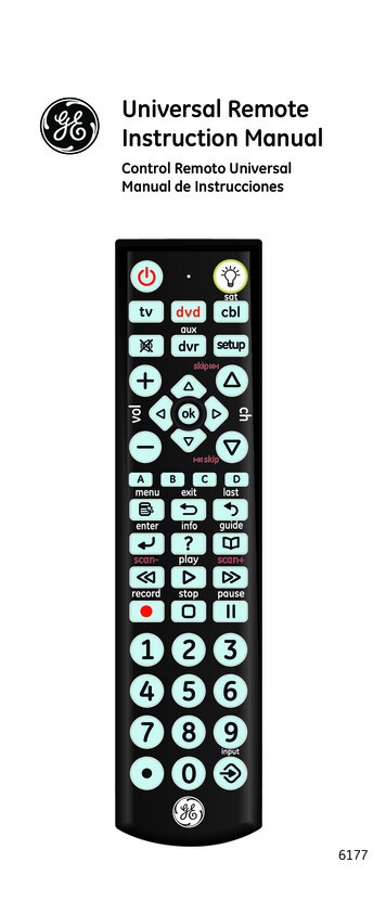
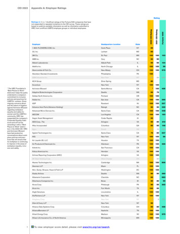
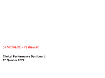
Section 2:RC-100 System OverviewThe RC-100 system allows wireless control of multiple scoring anddisplay applications. This system is made up of two distinct hardwarecomponents: the RC-100 wireless handheld controller, and the RC-100wireless Base Station.The RC-100 wireless handheld controller (Figure 2) includes a 4x4keypad and a 97x32 liquid crystal display (LCD). The RC-100 wirelesshandheld controller is used to enter information to be displayed on ascoreboard or display. The handheld operates using a 900 MHz radiowith internal antenna and comes with a rechargeable Ni-MH (NickelMetal Hydride) 2000 mAh battery which provides 8-10 hours ofoperation. An RC-100 system may include multiple RC-100 wirelesshandheld controllers.The RC-100 wireless Base Station processes information received fromthe wireless handheld controllers and sends this information to thescoreboard or another external controller. Based on the application, anRC-100 wireless receiver may be mounted inside the display (Figure 3),or placed in an external tabletop enclosure (Figure 4). An outdoorenclosure is also available for certain applications.Figure 3: Internal RC-100 ReceiverFigure 2: RC-100 WirelessHandheld ControllerFigure 4: External RC-100 Base Station(Tabletop Enclosure)Important Installation Range ConsiderationsThe wireless Base Station must be located at least 10' (3 m) from the wireless handheld controller andno more than 500' (152 m) away. If the wireless handheld is used outside this range, the wirelesshandheld signal may drop out. Ideally, the handheld controller should have a clear line-of-sight tothe Base Station antenna. Make sure the Base Station antenna is pointed straight up for best reception(it should look like a capital “L” when viewed from the side).RC-100 System Overview5
Section 3:RC-100 Base StationThe RC-100 wireless Base Station is used to communicate with all RC-100 wireless handheldcontrollers on the same channel setting. The RC-100 wireless Base Station also is used to updateconnected displays based with information entered on the wireless handheld controller.The wireless Base Station includes two switches that must be set to specify the function number andchannel of operation. Refer to Section 3.1 and Section 3.2, respectively. In addition, the Base Stationincludes a server/client jumper that must be set to “Client Mode” in some scenarios that featuremultiple displays. Refer to Section 3.4 for more information.3.1Function SettingThe desired RC-100 system function must be configured in the wireless Base Station. A list ofpossible current functions is shown below, along with the corresponding Function se Station Server Mode*)Default Function(last power up function)CAN Handheld (Judges') ConsoleGEN I All Sport Scoreboard ControllerDataTime/Data Master Display ControlReservedGEN II All Sport Scoreboard ReservedReservedReservedReservedReset Memory/Test**Function(Base Station Client Mode*)All Display GroupsDisplay Group 1Display Group 2Display Group 3Display Group 4Display Group 2Reset Memory/Test*** The function of the Base Station depends on whether it is in Server or Client mode. For aserver Base Station, the Function switch sets up the desired application. For a client BaseStation, the Function switch sets up the display group to which this display belongs.**Function Setting “F” is a special setting which resets all saved memory parameters back todefaults. This can be used for situations such as when a password needs to be reset. To usethis function, cycle power to the wireless Base Station with the switch in this position andleave on for 10 seconds. Remove power, change to the desired function and continue. Allsaved memory parameters will be set back to default.RC-100 Base Station7
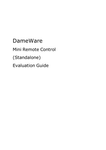
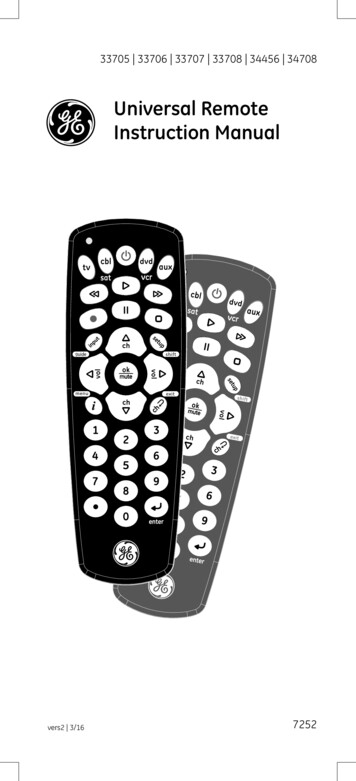
Selecting FunctionsRefer to Figure 5 for the wireless Base Station circuit board assembly drawing.To access the circuit board: For external Base Station enclosures, remove the two screws securing the top cover,and lift it off.For internal Base Stations, refer to the scoreboard/display manual for componentlocation and access instructions.After exposing Base Station circuit board, use a small flathead screwdriver to turn the “S2”rotary switch labeled “FUNCTION” to the desired Function Setting.Function Select SwitchFigure 5: Function Select Switch (Internal Receiver)After 5 seconds, the wireless Base Station Server will change its function to match the newswitch setting. (Any connected wireless handheld controllers should change as well.)When the wireless Base Station Server is turned off and back on, it will always default tothe function set on the switch.All Sport Scoreboard Controller FunctionThe All Sport Scoreboard Controller will normally operate with the Function Setting “5”selected. However, to support legacy products, Gen I mode of operation may be selected byswitching the Function Setting to “2”.Gen I OperationFunction Setting “2” allows Daktronics Gen I handheld controllers to communicate with GenII Base Stations.Gen II handheld controllers will recognize which generation Base Station they arecommunicating with. On first time power-up, the initialization of the radio will take a littlelonger while it attempts to recognize which generation Base Station is present.After a successful connection, the handheld controller will recognize and connectimmediately with that generation of Base Station.8RC-100 Base Station
Keep in mind the following when using the Gen I mode of operation: Gen I handheld controllers or Base Stations will not operate in Function “5”. All Base Stations operating at the same location must be set to the same Function. Gen I handheld controllers display ED14905 Version 1.6 or lower on the LCD atpower-up. Gen I Base Stations are labeled ED14906 Version 2.1 or lower. Gen II handheld controllers displ
All Sport Operation Manual ED-15133 Rev 7 -26 September 2012 201 Daktronics Drive PO Box 5128 Brookings, SD 57006-5128 Tel: 1-800-DAKTRONICS (1-800-325-8766) Fax: 605-697-4746 www.daktronics.com . ED-15133 Product 1110