Transcription
4-Inch LED Bar-DigitLocker Room ClockDisplay ManualRev 5 – 1 December 2015DD1732287ModelsTI-2031TI-3031201 Daktronics Drive PO Box 5128 Brookings, SD 57006-5128Tel: 1-800-DAKTRONICS (1-800-325-8766) Fax: 605-697-4746www.daktronics.com/support
DD1732287Product 1237Rev 5 – 1 December 2015daktronics, inc.Copyright 2011-2015All rights reserved. While every precaution has been taken in the preparation of this manual, the publisher assumes noresponsibility for errors or omissions. No part of this book covered by the copyrights hereon may be reproduced or copied in anyform or by any means – graphic, electronic, or mechanical, including photocopying, taping, or information storage, and retrievalsystems – without written permission of the publisher.All Sport is a registered trademark of Daktronics, Inc. All other trademarks are property of their respective companies.
Table of ContentsSection 1:1.11.21.31.41.5Introduction. 1Resources. 1Specifications Label. 1Daktronics Nomenclature. 1Control Console. 2Specifications. 2Section 2:2.12.2Mechanical & Electrical Installation. 3Surface Mount Method. 3Flush Mount Method. 4Section 3:3.13.23.33.4Maintenance & Troubleshooting. 5Troubleshooting Table. 5Component Access. 5LED Drivers . 5Replacement Parts. 5Section 4:4.1Daktronics Exchange and Repair & Return Programs. 7Exchange Program. 7Before Contacting Daktronics. 7Repair & Return Program. 8Shipping Address. 8Daktronics Warranty & Limitation of Liability. 84.24.3Appendix A:Reference Drawings. 9Appendix B:Daktronics Warranty & Limitation of Liability. 15Table of Contentsi
Section 1:IntroductionThis manual explains the installation and maintenance of Daktronics locker room clocks. For additionalinformation regarding the safety, installation, operation, or service of this system, refer to the DaktronicsCustomer Service contact information in Section 4.IMPORTANT SAFEGUARDS Read and understand all instructions before beginning the installation process. Disconnect the display power when not in use or when servicing. Disconnect the display power before servicing power supplies to avoid electrical shock.Power supplies run on high voltage and may cause physical injury if touched while powered. Do not modify the structure or attach any panels or coverings to the display without the expresswritten consent of Daktronics. Do not disassemble control equipment or electronic controls of the display; failure to follow thissafeguard will make the warranty null and void. Do not drop the control equipment or allow it to get wet.This manual is not specific to a particular installation. Project-specific information takes precedence over anyother general information found in this manual.1.1ResourcesFigure 1 illustrates a Daktronics drawing label. This manualrefers to drawings by listing the last set of digits and the letterpreceding them. In the example, the drawing would be referredto as Drawing D-1007804. All references to drawing numbers,appendices, figures, or other manuals are presented in boldtypeface. Any drawings referenced in a particular section arelisted at the beginning of it as shown below:Drawing NumberFigure 1: Drawing LabelReference Drawings:System Riser Diagram. Drawing D-1007804Daktronics identifies manuals by the DD or ED number located on the cover page. For example, this manualwould be referred to as DD1732287.1.2Specifications LabelPower specifications as well as serial and model numberinformation can be found on an ID label on the display,similar to the one shown in Figure 2.ASSY NO.SER. NO.MFG DATEDAKTRONICS201 DAKTRONICS DR.BROOKINGS, SD 57006-5128PHONE 800-325-8766LL-2306 R01Figure 2: Specifications LabelPlease have the assembly number, model number, and the date manufactured on hand when callingDaktronics customer service to ensure the request is serviced as quickly as possible. Knowing the facilityname and/or job number will also be helpful.1.3Daktronics NomenclatureMost display components have a white label that lists the part number (Figure 3).Part numbers will also appear on certain drawings. If a component is not found in theReplacement Parts List in Section 3.4, use the label to order a replacement. Section 4describes the Daktronics Exchange Policy and the Repair & Return Program. Refer tothese instructions if replacing or repairing any display component.Introduction0P-1127-0024SN:246502/19/12 Rev. 1Figure 3: Part Label1
Main Component Labels1.4Accessory LabelsPart TypePart NumberComponentLabelIndividual circuit board0P-XXXX-XXXXAssembly; a collection ofcircuit boardsTBXX0A-XXXX-XXXXTermination block forpower or signal cableGrounding pointEXXWire or cableW-XXXXPower or signal jackJXXFuseF-XXXXTransformerT-XXXXPower or signal plug forthe opposite jackPXXMetal partM-XXXFabricated metal assembly0S-XXXXXXSpecially ordered partPR-XXXXX-XControl ConsoleDaktronics locker room clocks are typically controlled by the same control console as the scoreboard(s) in thefacility. Refer to Drawing A-102198 in Appendix A for an example of how all the equipment works together.The locker room clocks are designed for use with All Sport 1600, 4000, 5000 or 5500 series consoles. Refer tothe following manuals for operating instructions:ModelControl ConsoleTI-2031All Sport 5000 Series Control Console Operation Manual (ED-11976)All Sport 4000 Series Control Console Operation Manual (ED-9999)All Sport 1600 Series Control Console Operation Manual (ED-12462)TI-3031All Sport 5500 Series Control Console Operations Manual (ED-16809)All of the above manuals are available online at www.daktronics.com/manuals.1.5SpecificationsThis section shows all of the mechanical specifications and power requirements for each display in thismanual. Models are listed in alphanumeric order.Note: All displays require a 120 VAC, 15 A circuit. Displays with a 240 VAC power requirement arealso available.ModelTI-2031TI-3031Dimensions:Height, Width, Depth8" H, 15" W, 3.25" D*(203 mm, 381 mm, 83 mm)Weight4 lb(1.8 kg)Watts40 WAmps120 / 240 V AC0.3 A / 0.2 A* Flush mount depth is 1.375" (35 mm).2Introduction
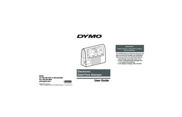
Section 2:Mechanical & Electrical InstallationThe TI-2031 and TI-3031 locker room clocks are connected to the signal from the main scoreboard in thefacility and will display the same time that is shown on the scoreboard.There are two primary methods of installing these locker room clocks: 1) surface mounted on the wall withmounting screws or anchors, or 2) flush mounted in the wall between standard spaced 16" (406 mm) studs.2.1Surface Mount MethodReference Drawings:System Riser- Remote Radio Receiver. Drawing B-260394Installation DWG; TI-2031/3031 Locker Room Clock. Drawing B-1064515The surface mount cabinet mounts centered over an electrical outlet and uses the deep rear mounting panel.1.Drill holes in the wall and install anchors or screws at the locations shown in Drawing B-1064515.The customer is responsible for providing mounting anchors or screws.2.Install a 120 VAC, 15 Amp electrical outlet or use an existing outlet that is located where the displaywill be installed. The outlet should be positioned behind the clock cabinet so that the wall packtransformer fits in the recessed area of the rear mounting panel.3.Mount the rear panel on anchor screws and tighten.4.Route the signal cable to the clock mounting location and allow it to extend at least 12" (305 mm)beyond the wall.5.Connect the signal wire to plug P-1388 signal terminal on the left side of the display (when viewedfrom the rear). Connect the red signal wire to the positive ( ) jack labeled “CL-IN” and the whitesignal wire to the negative (-) jack labeled “CL-IN”.Note: For installations with radio control from the All Sport console, refer to Drawing B-260934.6.Plug the wall pack transformer into the power jack located below the signal terminal, and plug thewall pack into the electrical outlet.7.Line up and mate the rear and front cabinet pieces. Attach the pieces together with included screws.Mechanical & Electrical Installation3
2.2Flush Mount MethodReference Drawings:System Riser- Remote Radio Receiver. Drawing B-260394Installation DWG; TI-2031/3031 Locker Room Clock. Drawing B-1064515The flush mount cabinet mounts between two 2x4 studs and uses the flush mount rear panel.1.Drill holes in the wall and install anchors or screws at the locations shown in Drawing B-1064515.The customer is responsible for providing mounting anchors or screws.2.Rough out the power supply and signal recess behind cabinet mounting location as depicted inDrawing B-1064515.3.Install a 120 VAC, 15 Amp electrical outlet on the stud behind the drywall behind the opening for theclock. This will allow the wall pack transformer to be plugged in and be out of the way of the clockwhen the clock is installed in the wall.4.Route the signal cable to the clock mounting location and allow it to extend at least 12" (305 mm)beyond the wall.5.Plug the wall pack transformer into the outlet.6.Mount the flush-style rear cabinet panel and tighten the anchor screws as needed.7.Connect the signal wire to plug P-1388 signal terminal on the left side of the display (when viewedfrom the rear). Connect the red signal wire to the positive ( ) jack labeled “CL-IN” and the whitesignal wire to the negative (-) jack labeled “CL-IN”.Note: For installations with radio control from the All Sport console, refer to Drawing B-260934.48.Plug the wall pack transformer into the power jack located below the signal terminal.9.Line up and mate the rear and front cabinet pieces. Attach the pieces together with included screws.Mechanical & Electrical Installation
Section 3:Maintenance & TroubleshootingDisconnect power before doing any repair or maintenance work on the display. Permit only qualified servicepersonnel to access internal display electronics. Disconnect power when not using the display.3.1Troubleshooting TableThe table below lists potential problems with the display and indicates possible causes. This list does notinclude every symptom that may be encountered, but it does present several of the most common situationsthat may occur.3.2Symptom/ConditionPossible CauseDisplay will not light Console not connected or poor connectionNo power to the control consoleNo power to the displayLoose incoming signal terminal at the displayGarbled display Control console malfunctionDriver malfunctionDigit will not light Driver malfunctionSegment will not light or stays lit Driver malfunctionComponent AccessTo gain access to the internal components of the display (surface mount):3.31.Remove top and bottom screws connecting front and rear cabinet.2.Separate the front and rear cabinet pieces.3.Unplug both the signal and power wires from the rear of the display.4.Remove screws holding circuit board to front of the cabinet.LED DriversThe LED driver performs the task of switching digits on and off. Locker room clock drivers contain all fourLED digits together in one assembly. Locker room clock drivers have two connectors that provide power andsignal to and from the driver:Connector #3.4FunctionJ2Power InputTB1Signal in and outReplacement PartsThe following table contains display components that may require replacement. Many of the other displaycomponents will have attached part number labels.Part DescriptionDaktronics Part #AS5K 4 Col Clock w/ DriverTransformer (240 V models)Transformer (120 V models)0P-1150-0259T-1106T-1118See Section 4 for information on Daktronics Exchange and Repair and Return program.Maintenance & Troubleshooting5
Section 4:4.1Daktronics Exchange and Repair & ReturnProgramsExchange ProgramThe Daktronics Exchange Program is a service for quickly replacing key components in need of repair.If a component fails, Daktronics sends a replacement part to the customer who, in turn, returns the failedcomponent to Daktronics. This decreases equipment downtime. Customers who follow the programguidelines explained below will receive this service.Before Contacting DaktronicsIdentify these important numbers:Display Serial Number:Display Model Number:Job/Contract Number:Date Manufactured/Installed:Daktronics Customer ID Number:To participate in the Exchange Program, follow these steps:1.2.Call Daktronics Customer Service.Market DescriptionCustomer Service NumberSchools (including community/junior colleges), religiousorganizations, municipal clubs, and community centers877-605-1115Universities and professional sporting events, live eventsfor auditoriums, and arenas866-343-6018When the new exchange part is received, mail the old part to Daktronics.If the replacement part fixes the problem, send in the problem part which is being replaced.a.Package the old part in the same shipping materials in which the replacement part arrived.b. Fill out and attach the enclosed UPS shipping document.c.3.Ship the part to Daktronics.The defective or unused parts must be returned to Daktronics within 5 weeks of initialorder shipment.If any part is not returned within five (5) weeks, a non-refundable invoice will be presented to thecustomer for the costs of replenishing the exchange parts inventory with a new part.Daktronics reserves the right to refuse parts that have been damaged due to acts of nature or causesother than normal wear and tear.Daktronics Exchange and Repair & Return Programs7
4.2Repair & Return ProgramFor items not subject to exchange, Daktronics offers a Repair & Return Program. To send a part for repair,follow these steps:1.Call or fax Daktronics Customer Service.Refer to the appropriate market phone number in the chart on the previous page.Fax: 605-697-44442.Receive a case number before shipping.This expedites repair of the part.3.Package and pad the item carefully to prevent damage during shipment.Electronic components, such as as printed circuit boards, should be placed in an antistatic bag beforeboxing. Daktronics does not recommend using packing peanuts when shipping.4.Enclose: name address phone number the case number a clear description of symptomsShipping AddressDaktronics Customer Service[Case #]201 Daktronics Drive, Dock EBrookings, SD 570064.3Daktronics Warranty & Limitation of LiabilityThe Daktronics Warranty & Limitation of Liability is located in Appendix B. The Warranty is independent ofExtended Service agreements and is the authority in matters of service, repair, and display operation.8Daktronics Exchange and Repair & Return Programs
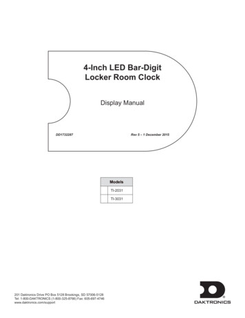
Appendix A:Reference DrawingsRefer to Section 1.1 for information regarding how to read the drawing number. These drawings are listed inalphanumeric order. Any contract-specific drawings take precedence over the general drawings.Drawing TitleDrawing NumberRiser Diagram: A/S 5000 Series High End System.A-102198System Riser- Remote Radio Receiver.B-260934Installation DWG; TI-2031/3031 Locker Room Clock.B-1064515Reference Drawings9
POWERININ -SIGNALOUT OUT -% WIRELESS RECEIVER4424DAKTRONICSDATA OUTPOWER INWILL ACCEPT12 TO 24 VAC OR DCRADIO IN RANGE5(9 ' .7521,&6 ,1& %522.,1*6 6' '2 127 6& /( '5 :,1*' 7( 129 5(9' 7( -81 5(9' 7( - 1 5(9' 7( -8/ 5(9' 7( 8* 5(9' 7( - 1 5(9' 7( - 1 83' 7(' )5217 9,(: '(7 ,/ ''(' /2& 7(' %( ,1' &/2&.127( 83' 7(' 5( 5 9,(: '(7 ,/ 83' 7(' 9,(: 2) 17(11 % 075% 03 /,1( ,1 7 ( :,5,1* 9,(: : 6 ,''(1 ',' &/( 1 1' 385*(2) 7 ( '5 :,1* 72 ),; ,783' 7(' 7(;7 3(5 7 ( *(1 5 ',2 '(9(/230(17% 0:0% 0:0& 1*(' 7 ( :,5( &2/256 21 7 ( 7% 2) 7 ( 5 ',2 5(&(,9(5 (1&/2685( % '.'(1 1&(' : // 287/(7 21 )5217 9,(:% -:& ''(' 7 72 )5217 9,(:% '0'7 ( &21&(376 (;35(66(' 1' '(7 ,/6 6 2:1 21 7 ,6'5 :,1* 5( &21),'(17, / 1' 35235,(7 5 '2 1275(352'8&( % 1 0( 16 :,7 287 7 ( (;35(66(':5,77(1 &216(17 2) ' .7521,&6 ,1& &23 5,* 7 ' .7521,&6 ,1& //63257 5 ',27,7/( 6 67(0 5,6(5 5(027( 5 ',2 5(&,(9(5'(6,*1'5 :1 '',1,1*6& /( 121(352-5(9' 7( 0 ''(' '(7 ,/6 72 6 2: 08/7,3/(&/2&. &21),*85 7,21% 1&%6 ((75(9 -2% 123 )81& 7 3( 6, (5 %' 7( 35 POWERLL-2567
STEP 1: ATTACH REAR COVER TO WALL-THE CLOCK SHIPS WITH TWO DIFFERENT REAR COVERS (FLUSH MOUNT AND SURFACE MOUNT)-THE FLUSH MOUNT OPTION REQUIRES CUTTING A HOLE IN THE WALL AND INSTALLING A 120VAC OUTLETINTERNAL TO THE WALL. OVERALL DEPTH OF CLOCK PROTRUDING FROM THE WALL IS 1.375". SEESUGGESTED CUTOUT AND OUTLET LOCATION IF THIS OPTION IS CHOSEN.-THE SURFACE MOUNT OPTION INSTALLS OVER ANY EXISTING 120VAC OUTLET. THE WALL PACKTRANSFORMER IS CONCEALED BEHIND THE REAR COVER. OVERALL DEPTH OF CLOCK IS 3.25"-CHOOSE DESIRED REAR COVER AND USE AS A JIG TO MARK THE MOUNTING HOLE LOCATIONSAT CHOSEN CLOCK LOCATION.-DRILL HOLES IN WALL AT MARKED LOCATIONS AND INSTALL APPROPRIATE WALL ANCHORS (CUSTOMER SUPPLIED)-PLACE REAR COVER OVER ANCHORS AND SECURE TO WALL WITH APPROPRIATE SCREWS (CUSTOMER SUPPLIED)THROUGH KEYHOLES IN REAR COVER.-COIL UP ANY EXTRA SIGNAL/POWER WIRES IN REAR COVER OR WALLDEPENDING ON MOUNTING METHOD CHOSEN-SLIDE FRONT CLOCK ASSEMBLY ONTO REAR COVER-ATTACH FRONT CLOCK ASSEMBLY TO REAR COVER WITH INCLUDED SCREWS(THREE ON TOP AND THREE ON BOTTOM)2X4 STUDS2X4 STUDS2X4 STUDSSHEETROCK120VACOUTLETSTEP 3: ATTACH FRONT CLOCK ASSEMBLY TO REAR COVERSHEETROCKMOUNTING SCREWS6.5004.500SHEETROCK.000WALL CUTOUT11.750120VAC OUTLETFRONT ROTATED VIEW(FLUSH MOUNT REAR COVER)FRONT VIEWFRONT ROTATED VIEWEXISTING120VAC OUTLETMOUNTING SCREWS14.500.0002.750WALL ANCHORS@2FRONT ROTATED VIEW(SURFACE MOUNT REAR COVER)(SUGGESTED CUTOUT AND OUTLET LOCATIONFOR FLUSH MOUNT REAR COVER)STEP 2: ROUTE/TERMINATE SIGNAL AND POWER-ROUTE SIGNAL CABLE TO THE REAR LEFT SIDE OF CLOCK LOCATION AND ALLOW IT TO EXTENDAT LEAST 12" BEYOND THE WALL-CONNECT SIGNAL WIRE TO PLUG P-1388 SIGNAL TERMINAL. CONNECT THE RED SIGNAL WIRE TO THEPOSITIVE ( )JACK LABELED "CL-IN" AND THE WHITE SIGNAL WIRE TO THE NEGATIVE ( - ) JACK LABELED"CL-IN"-SET DIP SWITCHES AS SHOWN IN THE CHART AT RIGHT BASED ON CONTROLLER TYPE.SWITCH POSITION UP IS ON, SWITCH POSITION DOWN IS OFF-PLUG THE WALL PACK TRANSFORMER INTO THE POWER JACK LOCATED BELOW THE SIGNAL TERMINAL,AND PLUG THE WALL PACK INTO THE ELECTRICAL OUTLET.REAR COVERTRANSFORMERALL SPORT 4000SWITCH 7: ONTI-3031P-1388 SIGNALTERMINAL BLOCKSIGNAL WIREALL SPORT 1600/3000/5000SWITCH 1: ONSWITCH 6: ONSWITCH 7: ONALL SPORT 5500SWITCH 1: ONSWITCH 6: ONPOWER JACKFOR TRANSFORMERPINP-1388 TABLEFUNCTION1CL IN-P2CL IN-N3CL OUT-P4CL OUT-N5SW IN-P6GND/SW IN-N7BUZZER-P8ALLSPORT 5000SWITCH 6: ONSEE DETAIL ABUZZER-NDIP SWITCHES GO FROM 8-1LEFT TO RIGHTSWITCH POSITION UP IS ONSWITCH POSITION DOWN IS OFFTIME OF DAY (T.O.D)DIP SWITCH LOCATION1TRANSFORMERPOWER JACKTI-2031PROSPORT 6000SWITCH 6: ONFRONT CLOCK ASSEMBLYP-1388SPRING CRIMPDIP SWITCH SETTING:DETAIL ASCALE 2/3DAKTRONICS, INC.FRONT CLOCK ASSEMBLYKNOCKOUTS FOR OPTIONALPOWER/SIGNAL ROUTINGLOCATED ON TOP AND BOTTOMOF REAR COVERFRONT ROTATED VIEWBROOKINGS, SD 570060302REAR ROTATED VIEW9 NOV 15ADDED TIME OF DAY NOTE UNDER DIP SWITCH SETTINGADDED P-1388 TABLEMTR23 MAR 15ADDED '3000' TO DIP SWITCH SETTING NOTESKDD0107 NOV 11REVDATE:ADDED TI-2031 AND TI-3031TO DIP SWITCH SETTINGDO NOT SCALE DRAWINGPROJ:TITLE:DESIGN:MBCBY:SCALE:THE CONCEPTS EXPRESSED AND DETAILS SHOWN ONTHIS DRAWING ARE CONFIDENTIAL AND PROPRIETARY.DO NOT REPRODUCE BY ANY MEANS WITHOUT THEEXPRESSED WRITTEN CONSENT OF DAKTRONICS, INC.COPYRIGHT 2011 DAKTRONICS, INC.INDOOR SCOREBOARDSINSTALLATION DWG; TI-2031/3031 LOCKER ROOM CLOCKDRAWN:MCARSRUMCARSRU1/15SHEET:REVJOB NO:1 OF 103P 1237FUNC-TYPE-SIZEE- 10 -BDATE:09-NOV-151064515
Appendix B:Daktronics Warranty & Limitation of LiabilityDaktronics Warranty & Limitation of Liability15
DAKTRONICS WARRANTY & LIMITATION OF LIABILITYThis Warranty and Limitation of Liability (the “Warranty”) sets forth the warranty provided by Daktronics with respect to the Equipment. By accepting delivery of theEquipment, Purchaser and End User agree to be bound by and accept these terms and conditions. Unless otherwise defined herein, all terms within the Warrantyshall have the same meaning and definition as provided elsewhere in the Agreement.DAKTRONICS WILL ONLY BE OBLIGATED TO HONOR THE WARRANTY SET FORTH IN THESE TERMS AND CONDITIONS UPON RECEIPT OF FULL PAYMENT FOR THEEQUIPMENT.1.Warranty CoverageA. Daktronics warrants to the original end user (the “End User”) that the Equipment will be free from Defects (as defined below) in materials andworkmanship for a period of one (1) year (the “Warranty Period”). The Warranty Period shall commence on the earlier of: (i) four weeks from the datethat the Equipment leaves Daktronics’ facility; or (ii) Substantial Completion as defined herein. The Warranty Period shall expire on the first anniversaryof the commencement date.“Substantial Completion” means the operational availability of the Equipment to the End User in accordance with the Equipment’s specifications, withoutregard to punch-list items, or other non-substantial items which do not affect the operation of the Equipment.B. Daktronics’ obligation under this Warranty is limited to, at Daktronics’ option, replacing or repairing, any Equipment or part thereof that is found byDaktronics not to conform to the Equipment’s specifications. Unless otherwise directed by Daktronics, any defective part or component shall bereturned to Daktronics for repair or replacement. This Warranty does not include on-site labor charges to remove or install these components.Daktronics may, at its option, provide on-site warranty service. Daktronics shall have a reasonable period of time to make such replacements or repairsand all labor associated therewith shall be performed during regular working hours. Regular working hours are Monday through Friday between 8:00a.m. and 5:00 p.m. at the location where labor is performed, excluding any holidays observed by Daktronics.C. Daktronics shall pay ground transportation charges for the return of any defective component of the Equipment. All such items shall be shipped byEnd User DDP Daktronics designated facility. If returned Equipment is repaired or replaced under the terms of this Warranty, Daktronics will prepayground transportation charges back to End USer and shall ship such items DDP End User’s designated facility; otherwise, End User shall paytransportation charges to return the Equipment back to the End User and such Equipment shall be shipped Ex Works Daktronics designated facility. Allreturns must be pre-approved by Daktronics before shipment. Daktronics shall not be obligated to pay freight for any unapproved return. End User shallpay any upgraded or expedited transportation charges.D. Any replacement parts or Equipment will be new or serviceably used, comparable in function and performance to the original part or Equipment, andwarranted for the remainder of the Warranty Period. Purchasing additional parts or Equipment from the Seller does not extend the Warranty Period.E. Defects shall be defined as follows. With regard to the Equipment (excepting LEDs), a “Defect” shall refer to a material variance from the designspecifications that prohibit the Equipment from operating for its intended use. With respect to LEDs, “Defects” are defined as LED pixels that cease toemit light. Unless otherwise expressly provided, this Warranty does not impose any duty or liability upon Daktronics for partial LED pixel degradation.Notwithstanding the foregoing, in no event does this Warranty include LED pixel degradation caused by UV light. This Warranty does not provide for thereplacement or installation of communication methods including but not limited to, wire, fiber optic cable, conduit, trenching, or for the purpose ofovercoming local site interference radio equipment substitutions.EXCEPT AS OTHERWISE EXPRESSLY SET FORTH IN THIS WARRANTY, TO THE MAXIMUM EXTENT PERMITTED BY APPLICABLE LAW, DAKTRONICS DISCLAIMSANY AND ALL OTHER PROMISES, REPRESENTATIONS AND WARRANTIES APPLICABLE TO THE EQUIPMENT AND REPLACES ALL OTHER WARRANTIES ORCONDITIONS, EXPRESS OR IMPLIED, INCLUDING, BUT NOT LIMITED TO, ANY IMPLIED WARRANTIES OR CONDITIONS OF MERCHANTABILITY, FITNESS FORA PARTICULAR PURPOSE, OR ACCURACY OR QUALITY OF DATA. OTHER ORAL OR WRITTEN INFORMATION OR ADVICE GIVEN BY DAKTRONICS, ITSAGENTS OR EMPLOYEES, SHALL NOT CREATE A WARRANTY OR IN ANY WAY INCREASE THE SCOPE OF THIS LIMITED WARRANTY.THIS LIMITED WARRANTY IS NOT TRANSFERABLE.2.Exclusion from Warranty CoverageThis Warranty does not impose any duty or liability upon Daktronics for any:A. damage occurring at any time, during shipment of Equipment unless otherwise provided for in the Agreement. When returning Equipment toDaktronics for repair or replacement, End User assumes all risk of loss or damage, agrees to use any shipping containers that might be provided byDaktronics, and to ship the Equipment in the manner prescribed by Daktronics;B. damage caused by: (i)the improper handling, installation, adjustment, use, repair, or service of the Equipment,or (ii) any physical damage whichincludes, but is not limited to, missing, broken, or cracked components resulting from non-electrical causes; altered, scratched, or fractured electronictraces; missing or gauged solder pads; cuts or clipped wires; crushed, cracked, punctured, or bent circuit boards; or tampering with any electronicconnections, provided that such damage is not caused by personnel of Daktronics or its authorized repair agents;C. damage caused by the failure to provide a continuously suitable environment, including, but not limited to: (i) neglect or misuse; (ii) improper powerincluding, without limitation, a failure or sudden surge of electrical power; (iii) improper air conditioning, humidity control, or other environmentalconditions outside of the Equipment’s technical specifications such as extreme temperatures, corrosives and metallic pollutants; or (iv) any other causeother than ordinary use;Copyright Daktronics, Inc. SL-02374 Rev 12 19Nov15 Page 1 of 2
DAKTRONICS WARRANTY & LIMITATION OF LIABILITYD. damage caused by fire, flood, earthquake, water, wind, lightning or other natural disaster, strike, inability to obtain materials or utilities, war,terrorism, civil disturbance, or any other cause beyond Daktronics’ reasonable control;E. failure to adjust, repair or replace any item of Equipment if it would be impractical for Daktronics personnel to do so because of connection of theEquipment by mechanical or electrical means to another device not supplied by Daktronics, or the existence of general environmental conditions at thesite that pose a danger to Daktronics personnel;F. statements made about the product by any salesperson, dealer, distributor or agent, unless
Display Manual DD1732287 Rev 5 - 1 December 2015 Models TI-2031 TI-3031. DD1732287 Product 1237 Rev 5 - 1 December 2015 daktronics, inc. . Figure 1 illustrates a Daktronics drawing label. This manual refers to drawings by listing the last set of digits and the letter preceding them. In the example, the drawing would be referred .


![Amalfi 180 Led Otto [28.01.22]](/img/23/022e99f7-d57e-51b4-8c41-152437a0d633.jpg)