Transcription
UNIVERSITY OF BENINBenin City, NigeriaTrainingTrainingCourseCourse 23BOREHOLE CONSTRUCTION ANDMAINTENANCEModule 1: Introduction and Current Challenges of GroundwaterManagementModule 2: WellsModule 3: Well Construction ProceduresModule 4: Water Sampling and AnalysisModule 5: Well Operation and Maintenance
MODULE 1: Introduction and Current Challenges of Groundwater Management1.0 IntroductionBoreholes are effective ways of tapping into the water bearing aquifer below the ground andpumping the water to the surface. Boreholes for extracting water consist essentially of avertically drilled shaft, a strong lining (casing) to prevent collapse of the walls, which includesa means of allowing clean water to enter the borehole space (screen), surface protection, and ameans of extracting water. The exploitation of ground water is a complicated process whichinvolves sinking a narrow shaft into the ground to reach the aquifer by using a drilling rig.Failure is sometimes experienced when carrying out borehole drilling operations or when usinginstalled borehole systems. These failures are caused by several complications which may arisefrom poor maintenance and rehabilitation of boreholes, lack of expertise poor choice oftechnology, and poor supervision of the drilling project In order to prevent these complications,the following measures must be taken: proper maintenance and rehabilitation of bore hole,proper pump installation and maintenance, proper supervision of borehole projects, the use ofappropriate drilling technology and the standardization of borehole design and drilling process.1.1 Current Challenges of Groundwater Management:The demand for groundwater is likely to increase in the future, the main reason being increasedwater use globally. Another reason may be the need to offset declining surface water availabilitydue to increasing temperature and decreasing precipitation and variability. The ever-increasingdemands along with natural stressors result into major challengesfor management of the vital natural resource in the country. Increasing populationis the major challenge where groundwater is the main source of safe water for drinking anddomestic purposes in rural and urban areas. Meeting the demand for increasing food productionis another major challenge for the world’s most densely populated country. Significant increasein dry season rice production through groundwater irrigation has made the country selfsufficient in rice, and production of all major crops has also increased. Demand for water isalso increasing due to faster rate of urbanization and industrializations; groundwater is themajor source of supply of municipal and industrial waters. The scenario of too much and toolittle surface water compels to use more and more groundwater all over the country, and largegroundwater is fresh and free from pathogenic contaminants over most of the country, andswitching to this source for drinking saved millions of lives over the year.
Occurrences of natural arsenic and salinity are the two most severe water quality issues of thecurrent time. Millions of people are still drinking arsenic above national and internationalstandards, whereas people living in the coastal areas are exposed to high salinity. Also, pollutionof groundwater due to municipal, agricultural and industrial sources is becoming widespread.People living in the slums in the big cities and adjacent to industrial towns suffer from safewater scarcity. Groundwater abstraction is increasing every day without a proper managementand monitoring plan. Conventional water pumps are becoming inoperative in many areas dueto declining water levels and need to be replaced by alternative expensive pumpingtechnologies. Groundwater governance is almost nonexistence in the country due to mainlylack of proper institutional arrangements. There are rules, regulations and policies to ensureproper management, but enforcement is lacking
1.2.0 Well Siting. Testing and Sampling1.2.1 Site Selection.Locating test bores and wells (and eventually water wells), if basedon technical criteria rather than convenience alone, begins with a site selection processbefore drilling or testing is planned. The goal should be pre-selection of the best possiblesites, and anticipation of both technical and other practical problems (e.g., neighbouringwells). This decision-making process involves a combination of hydrogeologicaladvisors, regulatory personnel, well drilling contractors, engineers, and the propertyowners involved. Tools include maps, aerial photographs, well logs and other relevantfile information from the area, and site inspection.1.2.2 Well Site Selection CriteriaThe six potential well site selection criteria are as follows:I.II.Groundwater production potential or yieldGroundwater quality, water quality;III.Vulnerability to known or suspected contamination or natural risks such asIV.Regulated distance from potential contaminant sources (e.g., septic tanks; oilV.VI.Potential for interference with other existing production wells, surface water flows, orPotential for interference with utilitiesPotential drilling sites being analyzed as potential water well sites should have somereasonable expectation of providing sufficient, potable water; meet regulatoryrequirements; and not pose unacceptable health or safety risks to workers or future waterusers. For public water supply wells, will the location allow for a defensible wellheadprotection area that does not include multiple potential pollution sources environmentallyimportant water uses (e.g., wetlands or springs) or areas;1.2.3 Test Borehole and Well Drilling.The purpose of drilling a test hole is to obtain information on ground water quality andformation materials, and to help establish essential "ground truth" at a specified location,including: formations;(1) The depth and extent of the water-bearing formations, or zones within(2) Thickness, nature, and areal extent of confining layers;(3) Existence of specific features of note (oily or sand seams)
(4) Water quality and actual yield and drawdown information.Location of test holes should be based on the objectives of the drilling project, and shouldbe selected based on available geologic information. For example, a test hole drilled totest a location for municipal water supply would be selected for maximumuncontaminated production. Test holes to coder the location of a contaminant plumewould be located based on existing knowledge of the plume and other field informationsuch as geophysical survey results. For a borehole to characterize a water-bearing fracturezone would be located based on maps, and aerial and geophysical surveys1.2.4 Drilling Logs and ReportsDrilling logs and other records of the test hole are critically important for laterevaluation in planning production wells. They may be the only site-specific geologicinformation available for a property or even the local area. Well drillers and geologistsmust prepare and keep complete logs setting for critical hydrogeological information,including: Descriptions of drilling methods;(1) The reference point for all depth measurements;(2) The depth at which each change of formation occurs;(3) The depth at which the first water was encountered;(4) The depth at which each stratum was encountered;(5) The thickness of each stratum;(6) The identification of the material of which each stratum is composed and its(7) Depths of major fractures or other features (e.g., oily seams);(8) The depth interval from which each water and formation sample was taken;(9) The depth at which hole diameters (bit sizes) change.(10) The depth to the static water level (SWL) and changes in SWL with(1 1) Total depth of completed well;(12) Any and all other pertinent information for a complete and accurate log, eg.,temperature, pH, appearance (colour), or odour of any water samples taken;(1 3) Depth or location of any lost drilling fluids, drilling materials or tools;(1 4) The depth and material used for the surface seal, if applicable;(1 5) The nominal hole diameter of the well bore above and below casing seal;(16) The amount of cement (number of sacks) installed for the seal, if applicable;(1 7) The depth and description of the well casing;
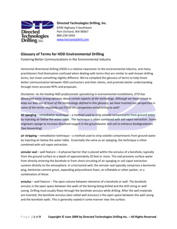
(1 8) The description (to include length, diameter, slot sizes, material, andmanufacturer) and location of well screens, or number, size and location of perforations;(1 9) The sealing off of water-bearing strata, if any, and the exact location thereof.1.2.5 Sample Report of Geophysical Investigation For A Borehole1. The geophysical survey was commissioned for the hydro geophysical characteristic of thesubsurface layers within the location of interest with a view to identifying location that couldbe drilled for a productive borehole.2. The Pre-drilling surveys aimed at delineating the several geologic units beneath the surfaceof the area and determining the suitability of drilling productive borehole within and outsidethe compound were carried out.3. Two locations were surveyed based on the Constant Separation Traverse were selected fordetailed investigations of the hydrogeological characteristics of the subsurface layers usingthe Schlumberger Array of Vertical Electrical Sounding (VES) study.4. The area is characterized by the presence of clayey overburden and fresh basement rocksoccurring at varying depth5. Based on the interpretation of the VES data, it is not advisable to drill a borehole within thecompound.
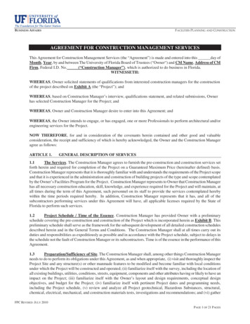
Figure1. Dual spaced and 4p density logs in a cased monitoring well showing completion asinterpreted from the logsThe Geophysical Survey was aimed at the following:a. Delineating the several geologic units beneath the surface of the areab. Ascertaining their hydro-geologic significance of these units.c. Determining the suitability of drilling a productive borehole at the points investigatedd. Making appropriate recommendation, if any, to ensure the success of the boreholes Inc.)
.
MODULE 2: TYPES OF WELLSWells are generally classified according to their type of construction as follows: Dug wells Bored wells Driven wells Jetted wells Drilled wells2.1.1 Dug WellsA dug well can furnish large quantities of water from shallow groundwater sources. Dugwells are uncommon because of the cost to install them and the potential for contaminationof the shallow aquifers and the wells themselves. Small-diameter wells can be constructedmanually with pick and shovel; larger wells are constructed with machinery suchas a clamshell bucket if the soil conditions are suitable.2.1.2 Bored WellsWells can be constructed quickly by boring where the geologic formation types are suitable.The formation must be soft enough for an auger to penetrate yet firm enough so itwill not cave in before a liner can be installed. The most suitable formations for boredwells are glacial till and alluvial valley deposits.A bored well is constructed by driving an auger into the earth. Bored wells are limitedto approximately 3 ft (1 m) in diameter and depths of 25 to 60 ft (8 to 18 m) under suitableconditions. As the auger penetrates, extensions are added to the drive shaft. A casing isforced into the hole as material is removed until the water-bearing strata are reached.Installing well screens or a perforated casing in the water-bearing sand and gravel layercompletes the well.2.1.3 Driven WellsDriven wells are simple to install; however, they are practical only when the water-bearingformations are relatively close to the surface and no boulders or bedrock exist in the soilor other formations between the surface and the aquifer. These wells consist of a pointedwell screen, called a drive point, and lengths of pipe attached to the point. The point has asteel tip that enables it to be pounded through some gravel or hardpan (a hard layer ofcemented soil near the ground surface) to the water-bearing formation (Figure 2-10).The diameter of the well pipe varies from as small as 1 in. (32 mm) up to 4 in. (107 mm).The maximum depth that can be achieved is generally 30 to 40 ft (9 to 12 m).
2.1.4 Jetted WellsA jetting pipe, which is equipped with a cutting knife on the bottom, is used to constructjetted wells. Water is pumped down the pipe and out of the drill bit against the bottom ofthe hole. The high-pressure water jet at the bottom of the pipe, in coordination with thecutting knife, loosens and removes the soil beneath the pipe and allows it to advancedownward.The casing is usually sunk as the drilling progresses until it passes through the waterbearingformation. The well screen connected to a smaller-diameter pipe is then loweredinto the casing, and the outer casing is withdrawn to expose the screen to the formation.These wells are generally suited to sandy formations and cannot be constructed by jettingthrough clay or hardpan or where there are boulders in the formation2.1.5 Drilled WellsDrilled wells are the most commonly used well type for public water supplies because theycan be installed in almost any situation. They can be constructed to extreme depths withsmall or large well diameters (up to 4 ft [1.5 m] or possibly larger). They are also the mostcommon type of well drilled for oil extraction.A drilled well is constructed using a drilling rig and casing. The rig makes the hole,and casing is placed in the hole to prevent the walls from collapsing. Screens are installedwhen water-bearing formations are encountered at one or more levels. The more commonlyused methods of drilling water supply wells are the following: Cable tool method Rotary hydraulic method Reverse-circulation rotary method California method Rotary air method Down-the-hole hammer method
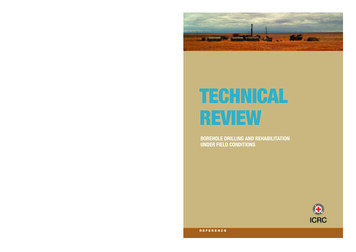
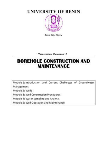
Figure 3: Typical borehole drilling showing water onCombination ofRotary& e ToolCasedHoleRotarycumDTHDuelRotaryOpenHoleFig. 4 Different types of drilling methods2.2.1 Cable tool methodThe percussion drilling method, commonly referred to as the cable tool method, has beenused extensively for wells of all sizes and depths but has waned in popularity because fasterand easier methods have been developed. There are many commercial varieties of cable tool
rigs. The operating principle for all varieties is the same. They use a bit at the end of a cablethat is repeatedly raised and dropped to fracture the soil material. The drilling tool has aclublike chisel edge that breaks the formation into small fragments. The reciprocatingmotion of the drilling tool mixes the loosened material into a sludge like substance.In each run of the drill, a depth of 3–6 ft (1–2 m) of the hole is drilled. The drill is thenpulled from the hole, and a bailer is used to remove the sludge. The bailer consists of asectionof casing 10 to 25 ft (3 to 8 m) long, slightly smaller in diameter than the drilled hole andhaving a check valve in the bottom. A casing is forced into the hole as soon as it isnecessary to prevent a cave-in of the walls.2.2.2 Rotary hydraulic methodIn the rotary method of well drilling, the hole is made by spinning a cylinder-shaped biton the bottom of multiple sections of drill pipe. The speed of rotation can be varied toachieve the best cutting effectiveness for different types of soil and rock.Drilling fluid (typically a thin slurry of clay and water, also called drilling mud) ispumped down to the bit (Figure 2-13). The fluid flows out through holes in the bit, picksup loosened material, and carries it up the borehole to the surface. The circulating fluidalso helps to cool the bit and keep the hole open during drilling. The fluid that flows to thesurface overflows from the well and is routed by a ditch into a settling pit or tub, where thecuttings settle out.2.2.3 Reverse-circulation rotary methodThe reverse-circulation rotary method of drilling differs from the regular rotary method inthat the drilling fluid is circulated in the opposite direction. The advantage is that becausewater is generally used as the drilling fluid, the method can be used where drilling additivesare undesirable. This method is also particularly well suited for constructing gravelpackedwells, because the drilling fluid mixture used in the regular rotary method tends toplug the walls of the well2.2.4 Rotary air methodThe rotary air method is similar to the rotary hydraulic method except that the drilling fluidis air rather than a mixture of water and clay. The method is suitable only for drilling inconsolidated-rock. Most large drill rigs are equipped for both air and hydraulic drilling so thatthe method may be changed as varying strata are encountered
2.2.5 Down-the-hole hammer methodA method frequently chosen to drill wells into rock uses a pneumatic hammer unit that isattached to the end of the drill pipe. The hammer is operated by compressed air. The airalso cleans the cuttings away from the bit and carries them to the surface. For most typesof rock, this is the fastest drilling method available.The drilling rig for this method must be furnished with a very large air compressor.Most standard rigs use 750 to 1,050 ft3/min (0.35 to 0.49 m3/sec) of air at a pressure of250 psi (1,700 kPa). Some rigs are also capable of operating at 350 psi (2,400 kPa), whichwill advance the drill twice as fast as a standard rig2.3.1 Problems in water well drillingThe most common drilling problems are:Loss of circulation.Cave-in hole (collapse)Bridging in wells.Crookedness of wells/deflection of wells.Pollution and corrosion in wells.Mud cake formation.Stacked tools.In light of the above explanation, for examples how the cause-and-effect analyses were donecited as follows: Problem: Loss of circulation. Practical Problem In Water Well Drilling And Pumping Testanalysis
Causes: Natural or intrinsic fractures, induced or created fractures, highly permeableformations, clogging of the opening of the drill bit are the main subsurface causes forcirculation loss problem. Effects: Partial or full interception of the drilling fluid which finally result in staking of thebit and the pipe may occur. In addition to this, at times, collapse of the borehole wall inunconsolidated formation may occur.Solution: Re-establishing circulation can involve several techniques. One can add commercialitems such as chopped paper, straw, cottonseed, and nut hulls to the mud pit. Sometimes,while the loss zone is grouted and re drilled, the grout is lost into the formation. In thissituation, you may have to set casing through the loss zone. Occasionally, reducing fluidvelocity while continuing to drill will plug the loss zone with drill cuttings. Re-establishingcirculation is usually a trial-and-error process. The longer well will drill without circulationthe more difficult it will to re-establish circulation.
MODULE 3: WELL CONSTRUCTION PROCEDURESWells can be constructed using several procedures. The principal factors affecting thechoice of construction method are how deep the well must be and whether the materialaround the well is gravel, clay, or rock. After a well has been constructed, it is usuallynecessaryto specially treat the well to obtain optimum productivity and water quality. Thelast step in well construction is to run pumping tests to confirm the well‘s capacity3.1.0 Well ComponentsComponents common to most wells are: Well casings Gravel pack Well screens Grouting3.1.1 Well Casing Selection and InstallationCasing is installed to prevent the collapse of the walls of the borehole, to excludepollutants from entering the water source at the well, and to provide a channel forconveying the water to the surface (or in the reverse direction, for injection). Casing alsoprovides a housing for the pump mechanism. but not exclusively, PVC) and stainlesssteel. Unfortunately, the terms "casing" and "pipe" can be confused. There is, however, adistinguishing difference between pipe and casing. Steel "pipe" is manufactured incylindrical form at the producing mill, whereas "casing" is made cylindrical by afabricator from steel sheets or plates. Such steel casing is fabricated to resist external andvertical forces, rather than the internal burst forces that line pipe is designed to resist.Plastic casing products are extruded, much like seamless steel casing, but like steelcasing, engineered (and selected during planning) to resist the pressures exerted by thesurrounding materials, forces imposed on it during installation, and corrosion by soil andwater environments. access to the water source from the surface through unstableformations, and through zones of actual or potential contamination. Casing should extendabove known levels of flooding, or be positively sealed against flooding flows. For wellsscreened in sand and gravel, casing should extend to at least five feet below the lowestestimated pumping level of a well to avoid excessive oxidation, clogging and corrosion at
the screen. In consolidated formations, casing should be sealed securely into firmbedrock .An exception may be the case where water immediately on top of rock is thetarget. In this case, the well design should be such that the casing is solidly installed andsediment and unsanitary water excluded. forces are known or expected to occur, a self-
sealing slip joint may be installed in the casing to allow for vertical movement andprevent collapse. Both carbon alloy steel and plastic well casing are now commonly usedsuccessfully around the world. Plastic casing is increasingly used due to its light weight,ease of installation, durability, and corrosion resistance. Concrete, fiberglass and asbestoscement casing have also been used with varying degrees of success. Less common metalcasing materials such as stainless steel, cupro-nickel alloys, silicon bronze, aluminium,and other nonferrous metals, can be used for casing in special situations where the naturalsoil and water-quality conditions (primarily severe corrosion potential) dictate theiremployment, and plastic cannot be used for some reason. Most common materials forwell casing are carbon steel, plastic (most commonly, Casing must be of the proper lengthto accomplish its purpose of providing secure Care must be exercised when placingcasing. In areas where subsidence or shifting3.1.2 Selecting Casing DiameterThe diameter of well casings installed depend on many factors:(1) Maximum flow capacity over the life of the well: Many times, the design ofthe well and casing size is determined by the need at the time the well is constructedwithout sufficient regard for future expansion or need.(2) Flow rate and total dynamic head requirements: The pump housing casing (inthe case of multiple casing-diameter sets) is determined by the bowl and motor diametersof the pumping equipment to be installed.(3) Geology and aquifer considerations: Multiple casings may be necessary insome installations to case off unwanted zones. Smaller-diameter casings and screens mayat times be set in deep wells below the pump. Further casings must fit and be properlysealed inside such conductor casings. If multiple casing sets are required, the casingsmust accommodate the total minimal annular space between liners andor the borehole forinstallation of grout seals or sealing devices.change depending on the method of installation.(4) Installation method: Casing diameters in multiple casing combinations may(5) Plumbness and alignment: Where borehole plumbness and alignment may be aproblem due to severe geologic drilling conditions, a larger casing diameter selection maybe prudent to allow for deviation.
(6) Water quality: Where clogging and corrosion may be expected (and they canbe commonly expected), too small a diameter casing may result in lodging of the pumplater.(7) Other devices: These may include water level transducers, airlines or3.2.0 Well GroutingFilling the annular space with material equal to or better than the materialremoved in drilling. (You don‘t run into slurries in the sub-surface.)3.2.1 Purposes of Well GroutWell grouting consists of filling an annular space between a casing and theformation or outer casing with an impervious material. The reasons for grouting are:(1) Protect ion of the aquifer, or aquifers (including the prevention of watermovement between aquifers) to maintain water quality and preserve the hydraulicresponse of the producing zone(s), anda subsurface zone.(2) Protection of the well against the entry of unwanted water from the surface or(3) Protection of the casing. This may be necessary to guard against attack bycorrosive waters, or where special assurance of structural integrity is desired. In this case,a satisfactory grouting program must result in complete envelopment of thedistortion of casing. They are also important in limiting or eliminating water circulationaround casing pipe, which contributes to corrosion3.2.2.Gravel packGravel pack is used in formations composed of fine-grained soils having uniform grainSize. A bed of gravel is installed around the screen, which in effect gives greater surfacearea for the infiltration of water into the well, while effectively blocking the entrance ofsand.The most common construction method is to install a large-diameter casing into thewater-bearing strata and then lower a small casing with a well screen into the hole. Thearea around the screen is then filled with gravel as the outer casing is withdrawncorresponding to the length of the screen. The gravel used must be clean, washed, andcomposed of well-rounded particles that are four to five times larger than the median size ofthe surrounding natural material. The size and gradation of the gravel are critical ineffectively blocking the entrance of fine sand.
3.3.0Well screens3.3.1 Purpose, Types and Design of Screened WellsWell screens are engineered intake structures that provide known slot openings topermit the entry of water while excluding formation particles. Screens are not designed toexclude the finest material. They are designed to hold out the coarser (more hydraulicallytransmissive) particle sizes, while relying on these particles to assist in excluding finermaterials. This is done by developing the well in such a way that the natural and, in somecases, artificially introduced, coarse-grained materials, retain finer-grained materialswhile enabling the water to enter without excessive head loss. A certain percentage offiner materials will be removed through the casing during development.3.3.2 Screen Type, Aperture Size, and Material Selectionanalysis of the particle sizes of the formation material and its water quality. Filter-packedscreens are selected to retain a filter pack selected to retain the formationScreens designs should provide an open area at least equal to the open area (porosity) ofthe surrounding formation, and provide design pumping volumes at an acceptableentrance velocity for the service life of the well. Screens design also must consider themechanical loading that the screen will ‗experience under installed conditions (tensile,collapse, shear forces) .3.3.3 Screen Type SelectionPunched (with material removed) and slotted Pipe. An economical screen can bemanufactured from pipe that has been mechanically punched (with the material removed)or slotted by saw or mill. The slots should have as uniform spacing and size as practical.Slots or holes should taper outward (widen toward the interior). Due to corrosionconcerns with metal pipe, slotted or punched construction should be limited tothermoplastic pipe material with sufficient strength to withstand the forces of installationand pumping when formed into screen. However, slotted or punched screens should notbe relied upon for strength in deep or unstable settings. Slotted or punched screensgenerally should be completed with artificial filter pack with slot sizes selected for thefilter pack.in it where material has not been removed, but opens outward to form louvers. Louverdesign screens may be selected where strength is a primary criterion for selection. Theopenings need to be uniform and their total area such that the entrance velocity at the
design condition must not exceed 1.2m per second per manufacturer recommendations3.4.0 Grouting3.4.1 Purposes of Well GroutWell grouting consists of filling an annular space between a casing and the formation orouter casing with an impervious material. The reasons for grouting are:(1) Protect ion of the aquifer, or aquifers (including the prevention of water movementbetween aquifers) to maintain water quality and preserve the hydraulicresponse of the producing zone(s), and a subsurface zone.(2) Protection of the well against the entry of unwanted water from the surface or(3) Protection of the casing. This may be necessary to guard against attack by corrosivewaters, or where special assurance of structural integrity is desired. In this case,a satisfactory grouting program must result in complete envelopment of the distortion ofcasing. They are also important in limiting or eliminating water circulationaround casing pipe, which contributes to corrosion3.4.2 Grouting RequirementsIn determining the specific grouting requirements of a well, consideration must begiven to existing surface and subsurface conditions, including the geology, hydrology andlocation of sources of pollution. To protect against contamination or pollution by surfacewaters or shallow subsurface waters (such as effluent from septic tanks) the annular spacemust be sealed to whatever depth is necessary to protect the well, whether 10 feet or morethan 1000 feet. In general, all casings lowered into the drilled borehole are fully grouted.Driven casings may be grouted, depending on subsurface and surface conditions.Formations which yield polluted water or water of an undesirable quality(untreatable to meet standards by practical means) must be adequately sealed off toprevent pollution or contamination of the adjacent water-bearing
uncontaminated production. Test holes to coder the location of a contaminant plume would be located based on existing knowledge . of . the plume and other field information such . as . geophysical survey results. For a borehole to characterize a water-bearing fracture zone would be located based . on . maps, and . aerial and geophysical surveys