Transcription
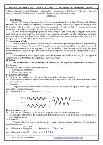
ENGINEERING PHYSICS UNIT I–PHYSICAL OPTICSSV COLLEGE OF ENGINEERING, KADAPASyllabus: Interference and diffraction – introduction – interference in thin film by reflection – Newton’srings – Fraunhofer diffraction due to single slit, double slit and diffraction gratingInterference1.IntroductionIn the 17th century, the properties of light were explained by Sir Isaac Newton and ChristianHuygens. Sir Isaac Newton was explained the properties of light by introducing Corpuscular theory in 1675.It explains reflection, refraction, and dispersion properties of light. It fails to explain interference,diffraction, polarization, photo electric effect, and double refraction.In 1679, Christian Huygens proposed the wave theory of light. According to Huygens wave theory,each point on the wave front is to be considered as a source of secondary wavelets. It explains reflection,refraction, dispersion, double refraction, diffraction, interference, and polarization properties of light. It failsto explain, photo electric effect, black body radiation etc,2. Interference of lightThe best evidence for the wave nature of light is interference phenomenon. This was experimentallydemonstrated by Thomas Young in 180, through double slit experiment. Due to interference, we willobserve many observations in our day today life, such as multiple colours on soap bubbles as well as on oilfilm when viewed under sun light. Interference concept is explained on the basis of superposition of wave’sconcept.When two light waves superimpose, then the resultant amplitude or intensity in the region ofsuperposition is different than the amplitude of individual waves.Definition:The modification in the distribution of intensity in the region of superposition is known asinterference.In case of interference pattern we observe two cases Constructive interference Destructive interferenceConstructive interference The waves are reaching at a point are in phase constructive interference occurs In constructive interference, the resultant amplitude is always equal to the sum of the amplitudes of twoindividual waves. ConditionThe path difference between the two waves is equal to the integral multiple of wave length (𝜆) theconstructive interference occurs.𝑝𝑎𝑡ℎ 𝑑𝑖𝑓𝑒𝑟𝑒𝑛𝑐𝑒 𝑛𝜆Where n 0, 1, 2, 3, 4 Destructive interference The waves are reaching at a point are in out of phase destructive interference occurs In Destructive interference, the resultant amplitude is always equal to the difference of the amplitudes oftwo individual waves. ConditionThe path difference between the two waves is equal to the odd integral multiple of λ/2 destructiveinterference occurs(2𝑛 1)𝜆𝑝𝑎𝑡ℎ 𝑑𝑖𝑓𝑒𝑟𝑒𝑛𝑐𝑒 Where n 1, 2, 3, 4 𝑜𝑟2(2𝑛 1)𝜆𝑝𝑎𝑡ℎ 𝑑𝑖𝑓𝑒𝑟𝑒𝑛𝑐𝑒 2Where n 0, 1, 2, 3, 4 Dr. P. SREENIVASULU REDDYwww.engineeringphysics.weebly.com1
ENGINEERING PHYSICS UNIT I–PHYSICAL OPTICSSV COLLEGE OF ENGINEERING, KADAPA3. Types of interference:For the formation of interference pattern, two coherent light sources are required. To get twocoherent sources form a single light source, two techniques are used. They are1. Division of wave front2. Division of amplitudeDivision of wave frontThe wave front from a single light source is divided into two parts using the phenomenon ofreflection, refraction, or diffraction. Young’s double slit experiment is belongs to this class of interference.Division of amplitudeThe amplitude of a single light beam is divided into two parts by parallel reflection or refraction.Newton’s ring experiment, Michelson’s interferometer is belongs to this class of interference.4. Conditions for interference1) Two light sources of emitting light waves should be coherent.2) Two sources must emit continuous light waves of same wavelengths or frequency.3) The separation between the two sources should be small.4) The distance between the two sources and the screen should be large.5) To view interference fringes, the background should be dark.6) The amplitude of light waves should be equal or nearly equal.7) The sources should be narrow.8) The sources should be monochromatic.5. Interference in thin films by reflectionPrinciple:The formation of colours in thin films can explained as due to the phenomenon of interference. Inthis example, the formation of interference pattern is by the division of amplitude.Consider a thin film of uniform thickness ’𝑡’ and refractive index ‘μ’. Let a monochromatic lightray AB is incident is on the upper surface of the film at point ‘A’ with an angle ‘𝑖’. The incidence light rayAB is divided into two light rays ray 1 (BC) and ray 2 (EF) by the division of amplitude principle. Thesetwo light rays BC and EF are parallel and superimpose and produce interference. The intensity ofinterference fringe depends up on the path difference between the ray 1 and ray 2.Ray 1Ray 2Dr. P. SREENIVASULU REDDYwww.engineeringphysics.weebly.com2
ENGINEERING PHYSICS UNIT I–PHYSICAL OPTICSSV COLLEGE OF ENGINEERING, KADAPAThe path difference between the light rays (1) and (2) is𝑝𝑎𝑡ℎ 𝑑𝑖𝑓𝑓𝑒𝑟𝑒𝑛𝑐𝑒 𝜇(𝐵𝐷 𝐷𝐸) 𝑖𝑛 𝑓𝑖𝑙𝑚 𝐵𝐻 𝑖𝑛 𝑎𝑖𝑟(1)𝐷𝐺𝑡𝑡From 𝐵𝐷𝐺cos 𝑟 𝐵𝐷 𝐵𝐷 𝐵𝐷 cos 𝑟Similarly from 𝐷𝐸𝐺𝐷𝐺𝑡𝑡cos 𝑟 𝐷𝐸 𝐷𝐸 𝐷𝐸 cos 𝑟𝑡 𝐵𝐷 𝐷𝐸 𝑐𝑜𝑠From 𝐵𝐸𝐻 𝐵𝐻 (𝐵𝐺 𝐺𝐸). sin 𝑖From 𝐵𝐷𝐺 𝑎𝑛𝑑 𝐷𝐸𝐺𝐵𝐻 (2𝑡 tan 𝑟). sin 𝑖From Snell’s law at point Bsin 𝑖 𝐵𝐻𝐵𝐸𝑟𝐵𝐻(2) 𝐵𝐺 𝐺𝐸𝐵𝐺 𝐺𝐸 𝑡 tan 𝑟sin 𝑖 𝜇 sin 𝑟 𝐵𝐻 2𝜇𝑡 tan 𝑟 . sin 𝑟(3)Substituting the equations (2) and (3) in equation (1), we get2𝜇𝑡𝑃𝑎𝑡ℎ 𝑑𝑖𝑓𝑓𝑒𝑟𝑒𝑛𝑐𝑒 cos 𝑟 2𝜇𝑡 tan 𝑟 . sin 𝑟2𝜇𝑡sin 2 𝑟 2𝜇𝑡.cos 𝑟cos 𝑟2𝜇𝑡(1 sin 2 𝑟) cos 𝑟2𝜇𝑡 𝑐𝑜𝑠 2 𝑟cos 𝑟 2𝜇𝑡 cos 𝑟At point B the light ray (1) is reflected at the surface of thin film (denser medium). So the light ray (1)undergoes a phase change π or an additional path difference λ/2.𝜆Total path difference 2𝜇𝑡 cos 𝑟 2Constructive interference (or Bright fridge)General condition; �𝑒 𝑛𝜆𝜆2𝜇𝑡 cos 𝑟 𝑛𝜆2𝜆2𝜇𝑡 cos 𝑟 𝑛𝜆 2(2𝑛 1)𝜆2𝜇𝑡 cos 𝑟 2Destructive interference (or Dark fridge)𝜆General condition: �𝑒 (2𝑛 1) 2𝜆 (2𝑛 1)𝜆2𝜇𝑡 cos 𝑟 222𝜇𝑡 cos 𝑟 𝑛𝜆6. Newton’s ringsPrinciple:The formation of Newton’s rings can explained as due to the phenomenon of interference. In thisexample, the formation of interference pattern is obtained by the division of amplitude.Experimental arrangementExperimental arrangement The experimental arrangement of Newton’s rings is shown in figure. The Plano -convex lens (L) of large radius of curvature is placed with its convex surface on the glassplate (P). The Plano convex lens touches the glass plate at O. A monochromatic light is allowed to fall normally on the lens with the help of glass plate M kept at 45 0to the incident monochromatic light. A part of light is reflected by the curved surface of the lens ‘L’ and a part of light is transmitted is partlyreflected back by the upper surface of the plane glass plate P.Dr. P. SREENIVASULU REDDYwww.engineeringphysics.weebly.com3
ENGINEERING PHYSICS UNIT I–PHYSICAL OPTICSSV COLLEGE OF ENGINEERING, KADAPA These reflected rays interfere and give rise to an interference pattern in the form of circular fringes.These rings are seen through microscope.MOExplanation of Newton’s ringsNewton’s rings are formed due to the interference between thelight rays reflected from the lower surface of the lens and theupper surface of the glass plate (or top and bottom surfaces of theair film).Let a vertical light ray AB be partially reflected from the curvedsurface of Plano convex lens with out phase change and partiallytransmitted light ray BC is again reflected at C on the glass platewith additional phase change of π or path difference λ/2.The path difference between the two rays is𝜆2𝜇𝑡 cos 𝑟 2For air film 𝜇 1 and for normal incidence 𝑟 0, so𝜆The path difference 2𝑡 2𝜆At the point of contact 𝑡 0, path difference is 2 i.e., the reflected and incidence light are out of phase anddestructive interference occur. So the center fringe is always dark.Constructive interference (or Bright fridge)General condition: �𝑒 𝑛𝜆𝜆2𝑡 𝑛𝜆2𝜆2𝑡 (2𝑛 1)2Where 𝑛 0, 1, 2, .Destructive interference (or Dark fridge)𝜆General condition: �𝑒 (2𝑛 1) 2𝜆𝜆2𝑡 (2𝑛 1)222𝑡 𝑛 𝜆Where 𝑛 0, 1, 2, .Theory of Newton’s ringsTo find the diameters of a dark and bright fringes construct a circle with the radius of curvature R of a lensL. Let us choose a point P at a distance ‘r’ from the center of lens and 𝑡 be the thickness of air film at pointp.Dr. P. SREENIVASULU REDDYwww.engineeringphysics.weebly.com4
ENGINEERING PHYSICS UNIT I–PHYSICAL OPTICSFrom the property of a circle 𝑁𝑃. 𝑁𝐵 𝑁𝑂. 𝑁𝐷𝑟. 𝑟 𝑡. (2𝑅 𝑡)𝑟 2 2𝑅𝑡 𝑡 2If t is small 𝑡 2 is negligible.𝑟 2 2𝑅𝑡𝑟2𝑡 2𝑅Bright ringsSV COLLEGE OF ENGINEERING, KADAPA𝜆For bright ring, the condition is 2𝑡 (2𝑛 1) 22 𝑟2𝜆 (2𝑛 1)2𝑅2(2𝑛 1)𝜆𝑅2By replacing r by D/2, the diameter of the bright ring is𝐷2 (2𝑛 1)𝜆𝑅 422𝐷 2(2𝑛 1)𝜆𝑅𝑟2 𝐷 2(2𝑛 1)𝜆𝑅𝐷 (2𝑛 1) 2𝜆𝑅𝐷 (2𝑛 1)𝐷 𝑜𝑑𝑑 𝑛𝑎𝑡𝑢𝑟𝑎𝑙 𝑛𝑢𝑚𝑏𝑒𝑟Dark ringsFor dark rings, the condition is2𝑡 𝑛 𝜆2 𝑟2 𝑛𝜆2𝑅𝑟 2 𝑛 𝜆𝑅By replacing r by D/2, the diameter of the dark ring is𝐷2 𝑛 𝜆𝑅4𝐷 4𝑛 𝜆𝑅𝐷 2 𝑛 𝜆𝑅𝐷 𝑛𝐷 𝑛𝑎𝑡𝑢𝑟𝑎𝑙 𝑛𝑢𝑚𝑏𝑒𝑟Note: suppose a liquid is taken in between the lens and glass plate having refractive index 𝜇, then thediameter of the dark nth dark ring can be written as 4𝑛 𝜆𝑅𝐷 𝜇7. Determination of wave length of sodium light using Newton’s ringsBy forming Newton’s rings and measuring the radii of the rings formed, we can calculate thewavelength of the light used if the radius of curvature of the lens is known. Let R be the radius of curvatureof the lens and 𝜆 is the wavelength of the light used.So the diameter of the mth dark ring can be written as𝐷𝑚 2 4 𝑚 𝜆 𝑅(1)Dr. P. SREENIVASULU REDDYwww.engineeringphysics.weebly.com5
ENGINEERING PHYSICS UNIT I–PHYSICAL OPTICSSV COLLEGE OF ENGINEERING, KADAPASimilarly the diameter of the nth dark ring is𝐷𝑛 2 4 𝑛 𝜆 𝑅(2)Subtracting equation (1) from (2) we get𝐷𝑛 2 𝐷𝑚 2 4 𝑛𝜆 𝑅 4 𝑚 𝜆 𝑅𝐷𝑛 2 𝐷𝑚 2 4 (𝑛 𝑚) 𝜆 𝑅𝐷𝑛 2 𝐷𝑚 2𝜆 4(𝑛 𝑚)𝑅Using the above relation wavelength can be calculated8. Determination of refractive index of a liquid using Newton’s ringsBy forming Newton’s rings and measuring the diameter of the rings formed, we can calculate therefractive index of the liquid.In air film, the diameters of the mth and nth dark rings are 𝐷𝑚 and 𝐷𝑛 are measured with the help oftravelling microscope.The diameter of the nth dark ring is𝐷𝑛 2 4 𝑛 𝜆 𝑅(1)The diameter of the mth dark ring is𝐷𝑚 2 4 𝑚𝜆 𝑅(2)Subtracting equation (1) from (2) we get𝐷𝑛 2 𝐷𝑚 2 4 (𝑛 𝑚) 𝜆 𝑅(3)The Newton’s rings setup is taken in a liquid. Now the air film is replaced by liquid film. In liquidfilm, the diameters of the same nth and mth dark rings are 𝐷′ 𝑛 and 𝐷′ 𝑚 are measured with the help oftravelling microscope.24𝑛𝜆𝑅𝐷′ 𝑛 AndSo𝐷′𝜇2𝑚 4𝑚𝜆𝑅𝜇22𝐷′ 𝑛 𝐷′ 𝑚 4 (𝑛 𝑚) 𝜆 𝑅(4)𝜇Dividing equation (3) by (4)𝐷𝑛 2 𝐷𝑚 22𝐷′ 𝑛 𝐷′ 𝑚2 4 (𝑛 𝑚) 𝜆 𝑅4 (𝑛 𝑚) 𝜆 𝑅𝜇𝐷𝑛 2 𝐷𝑚 22𝐷′ 𝑛 𝐷′ 𝑚2 𝜇Using the above relation 𝜇 can be calculated.Dr. P. SREENIVASULU REDDYwww.engineeringphysics.weebly.com6
ENGINEERING PHYSICS UNIT I–PHYSICAL OPTICSSV COLLEGE OF ENGINEERING, KADAPADiffraction1. IntroductionThe wave nature of light is first confirmed by the phenomenon of interference. Further it is confirmed bythe phenomenon of diffraction. The word ‘diffraction’ is derived from the Latin word diffractus whichmeans break to piece. When the light waves encounter an obstacle, they bend round the edges of theobstacle. The bending is predominant when the size of the obstacle is comparable with the wavelength oflight. The bending of light waves around the edges of an obstacle is diffraction. It was first observed byGremaldy.2. DiffractionWhen the light falls on the obstacle whose size is comparable with the wavelength of light thenthe light bends around the obstacle and enters in the geometrical shadow. This bending of light iscalled diffraction.When the light is incident on an obstacle AB, their corresponding shadow is completely dark on thescreen. Suppose the width of the slit is comparable to the wavelength of light, then the shadow consists ofbright and dark fringes. These fringes are formed due to the superposition of bended waves around thecorners of an obstacle. The amount of bending always depends on the size of the obstacle and wavelengthof light used.3. Types of diffractionThe diffraction phenomena are classified into two waysI.II.Fresnel diffractionFraunhofer diffraction.Fresnel diffraction:In this diffraction the source and screen are separated at finite distance. To study this diffractionlenses are not used because the source and screen separated at finite distance. This diffraction can be studiedin the direction of propagation of light. In this diffraction the incidence wave front must be spherical ofcylindrical.Fraunhofer diffraction:In this diffraction the source and screen are separated at infinite distance. To study this diffractionlenses are used because the source and screen separated at infinite distance. This diffraction can be studiedin any direction. In this diffraction the incidence wave front must be plane.4. Fraunhofer single slit diffraction:Let us consider a slit AB of width ‘e’.Let a plane wave front 𝑤𝑤 ′ of monochromatic light of wavelength λ is incident on the slit AB.According to Huygens principle, every point on the wave front is a source of secondary wavelets. Thewavelets spread out to the right in all directions.Dr. P. SREENIVASULU REDDYwww.engineeringphysics.weebly.com7
ENGINEERING PHYSICS UNIT I–PHYSICAL OPTICSSV COLLEGE OF ENGINEERING, KADAPAThe secondary wavelets which are travelling normal to the slit are brought to focus at point P0 on the screenby using the lens.These secondary wavelets have no path difference. Hence at point P0 the intensity is maxima and is knownas central maximum. The secondary wavelets travelling at an angle θ with the normal are focused at pointP1.Intensity at point P1 depends up on the path difference between the wavelets A and B reaching topoint P1. To find the path difference, a perpendicular AC is drawn to B from A.The path difference between the wavelets from A and B in the direction of θ is𝑝𝑎𝑡ℎ 𝑑𝑖𝑓𝑓𝑒𝑟𝑒𝑛𝑐𝑒 𝐵𝐶 𝐴𝐵 𝑠𝑖𝑛 𝜃 𝑒 𝑠𝑖𝑛 𝜃2𝜋(𝑝𝑎𝑡ℎ ��𝑠𝑒 𝑑𝑖𝑓𝑓𝑒𝑟𝑒𝑛𝑐𝑒 𝜆2𝜋(𝑒 sin 𝜃) 𝜆Let the width of the slit is divided into ‘n’ equal parts and the amplitude of the wave front each part is ‘a’.Then the phase difference between any two successive waves from these parts would be11 2𝜋𝑒 sin 𝜃(𝑝ℎ𝑎𝑠𝑒 𝑑𝑖𝑓𝑓𝑒𝑟𝑒𝑛𝑐𝑒) () 𝑑𝑛𝑛𝜆Using the vector addition method, the resultant amplitude R is𝑛𝑑𝑎 sin 2𝑅 𝑑sin 2sin 𝛼𝜋𝑒 sin 𝜃𝑅 𝐴 𝑛𝑎 𝐴 𝑎𝑛𝑑 𝛼 𝛼𝜆2sin𝛼Therefore resultant intensity 𝐼 𝑅 2 𝐴2 ( 𝛼 )Principal maximum:The resultant amplitude R can be written as𝐴𝛼3 𝛼5 𝛼7(𝛼 )𝛼3! 5! 7!𝐴𝛼𝛼2 𝛼4 𝛼6 (1 )𝛼3! 5! 7!𝛼2 𝛼4 𝛼6 𝐴 (1 )3! 5! 7!In the above expression for 𝛼 0 values the resultant amplitude is maximum𝑅 𝐴𝑅 𝐼𝑚𝑎𝑥 𝑅 2 𝐴2ThenDr. P. SREENIVASULU REDDYwww.engineeringphysics.weebly.com8
ENGINEERING PHYSICS UNIT I–PHYSICAL OPTICSSV COLLEGE OF ENGINEERING, KADAPA𝜋𝑒 sin 𝜃𝛼 0𝜆sin 𝜃 0𝜃 0For 𝜃 0 and 𝛼 0 value the resultant intensity is maximum at P0 and is known as principal maximum.Minimum intensity positions𝐼 Will be minimum when sin 𝛼 0𝛼 𝑚𝜋𝑚 1,2,3,4,5 .𝜋𝑒 sin 𝜃𝛼 𝑚𝜋𝜆𝜋𝑒 sin 𝜃 𝑚𝜆So we obtain the minimum intensity positions on either side of the principal maxima for all 𝛼 𝑚𝜋values.Secondary maximumIn between these minima secondary maxima positions are located. This can be obtained by differentiatingthe expression of 𝐼 w.r.t 𝛼 and equation to zero𝑑𝐼𝑑sin 𝛼 2 (𝐴2 [] ) 0𝑑𝛼 𝑑𝛼𝛼𝐴2𝐴22sin 𝛼 𝑑 sin 𝛼() 0𝛼 𝑑𝛼 𝛼2sin 𝛼 𝛼 cos 𝛼 sin 𝛼 [] 0𝛼𝛼2In the above expression 𝛼 can never equal to zero, soEither sin 𝛼 0 or 𝛼 cos 𝛼 sin 𝛼 0sin 𝛼 0 Gives the positions of minimaThe condition for getting the secondary maxima is𝛼 cos 𝛼 sin 𝛼 0𝛼 cos 𝛼 sin 𝛼𝛼 tan 𝛼The values of 𝛼 satisfying the above equation are obtained graphically by plotting the curves 𝑌 𝛼 and𝑌 tan 𝛼 on the same graph. The plots of 𝑌 𝛼 and 𝑌 tan 𝛼 is shown in figure.In the graph the two curves intersecting curves gives the values of satisfying of 𝛼 satisfying the above3𝜋5𝜋7𝜋equation. From the graph intersecting points are 𝛼 0, 2 , 2 , 2 From the above concepts the intensity distribution curve verses 𝛼 is shown in figure.Dr. P. SREENIVASULU REDDYwww.engineeringphysics.weebly.com9
ENGINEERING PHYSICS UNIT I–PHYSICAL OPTICS5. SV COLLEGE OF ENGINEERING, KADAPAFraunhofer double slit diffractionLet S1and S2 be the two slits equal width e and separated by a distance d.The distance between the two slits is (e d).A monochromatic light of wavelength λ is incident on the two slits.The diffracted light from these slits is focused on the screen by using a lens.The diffraction of a two slits is a combination of diffraction and interference.When the plane wave front is incident on the two slits, the secondary wavelets from these slits travel inall directions.The wavelets travelling in the direction of incident light is focused at P0. The wavelets travelling at anangle θ with the incident light are focused at point P1.sin 𝛼From Fraunhofer single slit experiment, the resultant amplitude is 𝑅 𝐴 𝛼So the amplitude of each secondary wavelet travelling with an angle θ can be taken as 𝐴wavelets interference and meet at point P1 on the screen.sin 𝛼𝛼. These twoTo find out the path difference between the two wavelets, let us draw a normal s1k to the wavelet S2.𝑃𝑎𝑡ℎ 𝑑𝑖𝑓𝑓𝑒𝑟𝑒𝑛𝑐𝑒 S2 𝑘S2 𝑘S2 𝑘From S1 S2 k sin 𝜃 S S (𝑒 𝑑)1 2S2 𝑘 (𝑒 𝑑 ) sin 𝜃2𝜋𝑝ℎ𝑎𝑠𝑒 𝑑𝑖𝑓𝑓𝑒𝑟𝑒𝑛𝑐𝑒 (𝑝𝑎𝑡ℎ (𝑒 𝑑 ) sin 𝜃 𝛿𝑝ℎ𝑎𝑠𝑒 𝑑𝑖𝑓𝑓𝑒𝑟𝑒𝑛𝑐𝑒 𝜆By using vector addition method, we can calculate the resultant amplitude at point P 1 by taking the resultantamplitudes of the two slits S1and S2 as sides of the triangle. The third side gives resultant amplitude.𝐴𝐶 2 𝐴𝐵 2 𝐵𝐶 2 2(𝐴𝐵)(𝐵𝐶) cos 𝛿Dr. P. SREENIVASULU REDDYwww.engineeringphysics.weebly.com10
ENGINEERING PHYSICS UNIT I–PHYSICAL OPTICSSV COLLEGE OF ENGINEERING, KADAPA22sin𝛼sin𝛼sin𝛼sin 𝛼𝑅 2 (𝐴) (𝐴) 2 (𝐴) (𝐴) cos 𝛿𝛼𝛼𝛼𝛼sin 𝛼 2𝑅 4 (𝐴) cos 2 𝛽𝛼2𝑤ℎ𝑒𝑟𝑒 𝛼 𝜋𝑒 sin 𝜃𝜋(𝑒 𝑑 ) sin 𝜃𝑎𝑛𝑑 𝛽 𝜆𝜆𝑅 2 4 (𝐴The resultant intensity𝐼 𝑅 2 4 (𝐴sin 𝛼 2) cos 2 𝛽𝛼sin 𝛼 2𝛼) cos 2 𝛽From the above equation, it is clear that the resultant intensity is a product of two factors i.e.,sin 𝛼 21. (𝐴 𝛼 ) Represents the diffraction pattern due to a single slit.2. cos2 𝛽 Represents the interference pattern due to wavelets from double slit.Diffraction effectThe diffraction pattern consists of central principal maxima for 𝛼 0 value.The secondary maxima of decreasing intensity are present on either side of the central maxima for 𝛼 3𝜋5𝜋7𝜋 2 , 2 , 2 values.Between the secondary maxima the minima values are present for 𝛼 𝜋, 2𝜋, values.In diffraction pattern the variation of 𝐼 w.r.t 𝛼 as shown in figure (a)Interference effectIn interference pattern the variation of cos2 𝛽 w.r.t 𝛽 as shown in figure (b)cos 2 𝛽 Represent the interference pattern.Interference maximum will occur for cos2 𝛽 1𝛽 𝑚𝜋𝑤ℎ𝑒𝑟𝑒 𝑚 0, 1, 2, 3, 4 𝛽 𝜋, 2𝜋, 3𝜋, 4𝜋 𝜋(𝑒 𝑑 ) sin 𝜃 𝑚𝜋𝜆(𝑒 𝑑 ) sin 𝜃 𝑚𝜆Interference minima will occur for cos2 𝛽 0𝛽 (2𝑚 1) 𝜋 2𝜋(𝑒 𝑑 ) sin 𝜃 (2𝑚 1) 𝜋 2𝜆(𝑒 𝑑 ) sin 𝜃 (2𝑚 1) 𝜆 2Intensity distribution:Figure (a), (b) and (c) represents the intensity variations of due to diffraction, interference and both effectsrespectively. From figure (c) it is clear that the resultant minima are not equal to zero.Dr. P. SREENIVASULU REDDYwww.engineeringphysics.weebly.com11
ENGINEERING PHYSICS UNIT I–PHYSICAL OPTICSSV COLLEGE OF ENGINEERING, KADAPA6. Diffraction gratingA set of large number of parallel slits of same width and separated by opaque spaces is known asdiffraction grating. Fraunhofer used the first grating consisting of a large number of parallel wires placedside by side very closely at regular separation. Now the gratings are constructed by ruling the equidistanceparallel lines on a transparent material such as glass with fine diamond point. The ruled lines are opaque tolight while the space between the two lines is transparent to light and act as a slit.Let ‘e’ be the width of line and‘d’ be the width of the slit. Then (e d) is known as grating element.If N is the number of lines per inch on the grating then𝑁(𝑒 𝑑) 1 𝑖𝑐ℎ 2.54 𝑐𝑚2.54 𝑐𝑚(𝑒 𝑑) 𝑁Commercial gratings are produced by taking the cost of actual grating on a transparent film like thatof cellulose acetate. Solution of cellulose acetate is poured on a ruled surface and allowed to dry to form athin film, detachable from the surface. This film of grating is kept between the two glass plates.Dr. P. SREENIVASULU REDDYwww.engineeringphysics.weebly.com12
ENGINEERING PHYSICS UNIT I–PHYSICAL OPTICS SV COLLEGE OF ENGINEERING, KADAPA Dr. P. SREENIVASULU REDDY www.engineeringphysics.weebly.com 4 These reflected rays interfere and give rise to an interference pattern in the form of c