Transcription
K ELECTRICALABSECTIONPOWER SUPPLY, GROUND & CIRCUIT ELEMENTSCDECONTENTSPOWER SUPPLY ROUTING CIRCUIT . 3Schematic . 3Wiring Diagram — POWER — . 5BATTERY POWER SUPPLY — IGNITION SW.IN ANY POSITION . 5ACCESSORY POWER SUPPLY — IGNITIONSW. IN ACC OR ON . 9IGNITION POWER SUPPLY — IGNITION SW.IN ON . 10IGNITION POWER SUPPLY — IGNITION SW.IN ON AND/OR START .11IPDM E/R (INTELLIGENT POWER DISTRIBUTIONMODULE ENGINE ROOM) . 14System Description . 14SYSTEMS CONTROLLED BY IPDM E/R . 14CAN COMMUNICATION LINE CONTROL . 14IPDM E/R STATUS CONTROL . 14CAN Communication System Description . 15FOR TCS MODELS . 15FOR A/T MODELS . 16FOR M/T MODELS . 18Function of Detecting Ignition Relay Malfunction . 19Auto Active Test . 19DESCRIPTION . 19OPERATION PROCEDURE . 19INSPECTION IN AUTO ACTIVE TEST MODE . 20Schematic . 22IPDM E/R FUSE AND RELAY ARRANGEMENT. 23IPDM E/R TERMINAL ARRANGEMENT . 23IPDM E/R Power/Ground Circuit Inspection . 23Removal and Installation of IPDM E/R . 24GROUND CIRCUIT . 26Ground Distribution . 26MAIN HARNESS . 26ENGINE ROOM HARNESS . 28ENGINE CONTROL HARNESS (QR25DE) . 30ENGINE CONTROL HARNESS (VQ35DE) . 32BODY HARNESS . 34BODY NO. 2 HARNESS . 35HARNESS . 37Revision: May 2004Harness Layout . 37HOW TO READ HARNESS LAYOUT . 37OUTLINE . 38MAIN HARNESS . 39ENGINE ROOM HARNESS (LH VIEW) . 41ENGINE ROOM HARNESS (RH VIEW) . 44ENGINE CONTROL HARNESS (QR25DE) . 46ENGINE CONTROL HARNESS (VQ35DE) . 48BODY HARNESS . 50BODY NO. 2 HARNESS . 52ROOM LAMP HARNESS . 54FRONT DOOR LH HARNESS . 55FRONT DOOR RH HARNESS . 55REAR DOOR LH HARNESS . 56REAR DOOR RH HARNESS . 56Wiring Diagram Codes (Cell Codes) . 57ELECTRICAL UNITS LOCATION . 60Electrical Units Location . 60ENGINE COMPARTMENT . 60PASSENGER COMPARTMENT . 61Fuse . 63Fusible Link . 63Circuit Breaker (Built Into BCM) . 63HARNESS CONNECTOR . 64Description . 64HARNESS CONNECTOR (TAB-LOCKINGTYPE) . 64HARNESS CONNECTOR (SLIDE-LOCKINGTYPE) . 65HARNESS CONNECTOR (DIRECT-CONNECTSRS COMPONENT TYPE) . 66JOINT CONNECTOR (J/C) . 67Terminal Arrangement . 67ELECTRICAL UNITS . 68Terminal Arrangement . 68STANDARDIZED RELAY . 69Description . 69NORMAL OPEN, NORMAL CLOSED ANDMIXED TYPE RELAYS . 69TYPE OF STANDARDIZED RELAYS . 69PG-12003 AltimaFGHIJPGLM
FUSE BLOCK-JUNCTION BOX(J/B) . 71Terminal Arrangement . 71Revision: May 2004FUSE AND FUSIBLE LINK BOX .72Terminal Arrangement .72PG-22003 Altima
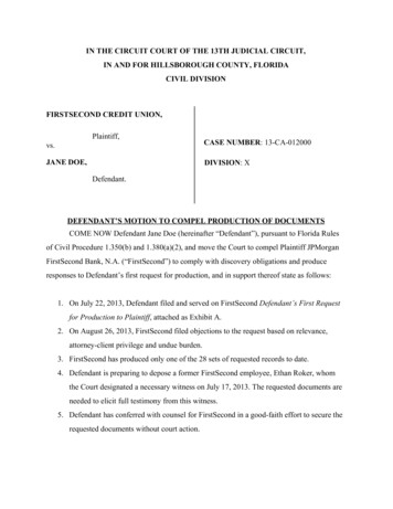
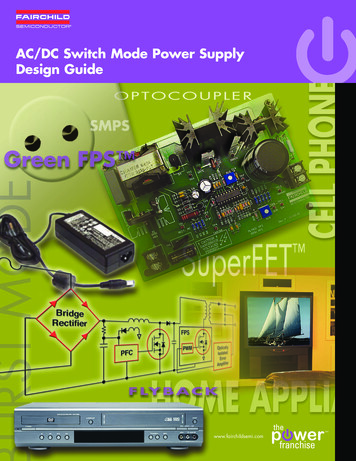
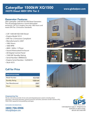
POWER SUPPLY ROUTING CIRCUITPOWER SUPPLY ROUTING CIRCUITSchematicPFP:24110AEKS003J6For detailed ground distribution, refer to PG-26, "Ground Distribution" .BCDEFGHIJPGLMWKWA0093ERevision: May 2004PG-32003 Altima
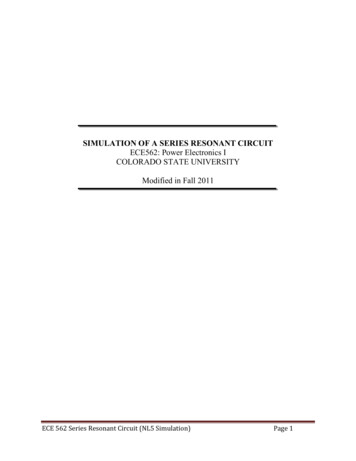
POWER SUPPLY ROUTING CIRCUITWKWA0094ERevision: May 2004PG-42003 Altima
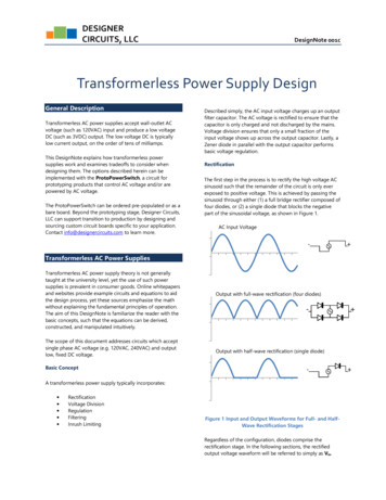
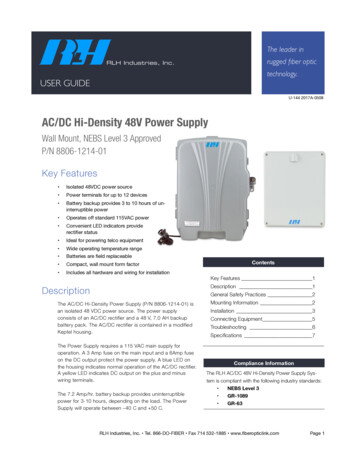
POWER SUPPLY ROUTING CIRCUITWiring Diagram — POWER —EKS003J7ABATTERY POWER SUPPLY — IGNITION SW. IN ANY POSITIONBCDEFGHIJPGLMWKWA0262ERevision: May 2004PG-52003 Altima
POWER SUPPLY ROUTING CIRCUITWKWA0263ERevision: May 2004PG-62003 Altima
POWER SUPPLY ROUTING CIRCUITABCDEFGHIJPGLMWKWA0264ERevision: May 2004PG-72003 Altima
POWER SUPPLY ROUTING CIRCUITWKWA0265ERevision: May 2004PG-82003 Altima
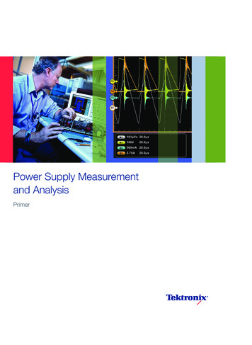
POWER SUPPLY ROUTING CIRCUITACCESSORY POWER SUPPLY — IGNITION SW. IN ACC OR ONABCDEFGHIJPGLMWKWA0266ERevision: May 2004PG-92003 Altima
POWER SUPPLY ROUTING CIRCUITIGNITION POWER SUPPLY — IGNITION SW. IN ONWKWA0089ERevision: May 2004PG-102003 Altima
POWER SUPPLY ROUTING CIRCUITIGNITION POWER SUPPLY — IGNITION SW. IN ON AND/OR STARTABCDEFGHIJPGLMWKWA0267ERevision: May 2004PG-112003 Altima
POWER SUPPLY ROUTING CIRCUITWKWA0268ERevision: May 2004PG-122003 Altima
POWER SUPPLY ROUTING CIRCUITABCDEFGHIJPGLMWKWA0269ERevision: May 2004PG-132003 Altima
IPDM E/R (INTELLIGENT POWER DISTRIBUTION MODULE ENGINE ROOM)IPDM E/R (INTELLIGENT POWER DISTRIBUTION MODULE ENGINE ROOM)PFP:284B7System DescriptionEKS003J8IPDM E/R (Intelligent Power Distribution Module Engine Room) integrates the relay box and fuse blockwhich were originally placed in engine compartment. It controls integrated relay via IPDM E/R control circuit. IPDM E/R-integrated control circuit performs ON-OFF operation of relay, CAN communication control, oilpressure switch signal reception, etc. It controls operation of each electrical part via BCM and CAN communication lines.CAUTION:All IPDM E/R-integrated relays cannot be removed. SYSTEMS CONTROLLED BY IPDM E/R1. Lamp controlUsing CAN communication line, it receives signal from BCM and controls the following lamps: Headlamps (Hi, Lo) Parking lamps Tail lamps Front fog lamps2. Wiper controlUsing CAN communication line, it receives signals from BCM and controls the front wipers.3. Rear window defogger relay controlUsing CAN communication line, it receives signals from BCM and controls the rear window defogger relay.4. A/C compressor controlUsing CAN communication line, it receives signal from ECM and controls the A/C relay.5. Cooling fan controlUsing CAN communication line, it receives signal from ECM and controls cooling fan relay.CAN COMMUNICATION LINE CONTROLWith CAN communication, by connecting each control unit using two communication lines (CAN L-line, CANH-line), it is possible to transmit maximum amount of information with minimum wiring. Each control unit cantransmit and receive data, and read necessary information only.1. Fail-safe control When CAN communication with other control units is impossible, IPDM E/R performs fail-safe control.After CAN communication recovers normally, it also returns to normal control. Operation of control parts by IPDM E/R during fail-safe mode is as follows:Controlled partsFail-safe modeHeadlampsHeadlamp relay (Lo) ONFront fog lampsFront fog lamp relay OFFTail and parking lampsTail lamp relay OFFFront wipersUntil ignition switch is turned OFF, status immediately before fail-safe control is performedis maintained.Rear window defoggerRear window defogger relay OFFCooling fanCooling fan (HI) ONA/C compressorA/C relay OFFIPDM E/R STATUS CONTROLIn order to save power, IPDM E/R switches status by itself based on each operating condition.1. CAN communication status CAN communication is normally performed with other control units. Individual unit control by IPDM E/R is normally performed.Revision: May 2004PG-142003 Altima
IPDM E/R (INTELLIGENT POWER DISTRIBUTION MODULE ENGINE ROOM)When sleep request signal is received from BCM, mode is switched to sleep waiting status.Sleep waiting status Process to stop CAN communication is activated. All systems controlled by IPDM E/R are stopped. When 3 seconds have elapsed after CAN communication with other control units is stopped, mode switches to sleep status.Sleep status IPDM E/R operates in low current-consumption mode. CAN communication is stopped. When a change in CAN communication line is detected, mode switches to CAN communication status. 2.3.CAN Communication System DescriptionEKS003J9CAN (Controller Area Network) is a serial communication line for real time application. It is an on-vehicle multiplex communication line with high data communication speed and excellent error detection ability. Many electronic control units are equipped onto a vehicle, and each control unit shares information and links with othercontrol units during operation (not independent). In CAN communication, control units are connected with 2communication lines (CAN H line, CAN L line) allowing a high rate of information transmission with less wiring.Each control unit transmits/receives data but selectively reads required data only.ABCDEFFOR TCS MODELSSystem diagramGHILKIA0015EJInput/output signal chartT: Transmit R: ReceiveSignalsEngine speed signalECMTCMCOMBINATIONMETERTREngine coolant temperature signalTRAccelerator pedal position signalTFuel consumption monitor signalTA/T warning lamp signalPGBCMABS/TCScontrol unitIPDM E/RLRMRTRTRR(R range only)RA/T position indicator signalRABS operation signalRTCS operation signalRAir conditioner switch signalRAir conditioner compressor signalRTA/C compressor request signalTRCooling fan motor operation signalRTCooling fan speed request signalTRTRTTPosition lights requestTRPosition lights statusRTLow beam requestTRRevision: May 2004RPG-152003 Altima
IPDM E/R (INTELLIGENT POWER DISTRIBUTION MODULE ENGINE ROOM)SignalsLow beam statusECMCOMBINATIONMETERTCMBCMRABS/TCScontrol unitIPDM E/RRTTRRTFront fog lights requestTRFront fog light statusRTHigh beam requestHigh beam statusRROD cancel switch signalRTBrake switch signalRTVehicle speed signalRTRTRROil pressure switchRSleep request1RTTSleep request2TN range switch signalRP range switch signalRRTTSeat belt buckle switch signalTRDoor switch signalRTRTail lamp requestRTRTurn indicator signalRTBuzzer output signalRTTrunk switch signalRTASCD main switch signalTRASCD cruise signalTRWiper operationRTWiper stop position signalRTRear window defogger switch signalTRRTRear window defogger control signalRFOR A/T MODELSSystem diagramLKIA0017EInput/output signal chartT: Transmit R: ReceiveSignalsECMTCMCOMBINATIONMETEREngine speed signalTREngine coolant temperature signalTRRevision: May 2004PG-16BCMIPDM E/R2003 Altima
IPDM E/R (INTELLIGENT POWER DISTRIBUTION MODULE ENGINE ROOM)SignalsECMAccelerator pedal position signalTFuel consumption monitor signalTA/T warning lamp signalTCMCOMBINATIONMETERBCMIPDM E/RRRTRTRBR(R range only)A/T position indicator signalRAir conditioner switch signalRAir conditioner compressor signalRTA/C compressor request signalTRCTR(QR25DE)TCooling fan motor operation signalRTCooling fan speed request signalTBlower fan switch signalRPosition lights requestTRPosition lights statusRTLow beam requestTRRTTRRTFront fog lights requestTRFront fog light statusRTLow beam statusRRHigh beam requestHigh beam statusRROD cancel switch signalRTBrake switch signalRTVehicle speed signalRTRTOil pressure switchRSleep request1RSleep request2RTP range switch signalRTTRRTRTail lamp requestRTRTurn indicator signalRTBuzzer output signalRTRTASCD cruise signalTRWiper operationRTWiper stop position signalRTRear window defogger switch signalTRRTRevision: May 2004RPG-17HJPGLDoor switch signalRGTRTFRTASCD main switch signalEISeat belt buckle switch signalTrunk switch signalDRTN range switch signalRear window defogger control signalA2003 AltimaM
IPDM E/R (INTELLIGENT POWER DISTRIBUTION MODULE ENGINE ROOM)FOR M/T MODELSSystem diagramLKIA0018EInput/output signal chartT: Transmit R: ReceiveSignalsECMEngine speed signalTEngine coolant temperature signalTCOMBINATIONMETERBCMIPDM E/RFuel consumption monitor signalTAir conditioner switch signalRAir conditioner compressor signalRTA/C compressor request signalTRBlower fan switch signalTR(QR25DE)TCooling fan motor operation signalRTCooling fan speed request signalTRPosition lights requestTRPosition lights statusRTLow beam requestTRRTTRLow beam statusRRHigh beam requestHigh beam statusRRTFront fog lights requestTRFront fog light statusRTVehicle speed signalRRTOil pressure switchRSleep request1RSleep request2TTTRSeat belt buckle switch signalTRDoor switch signalRTRTail lamp requestRTRTurn indicator signalRTBuzzer output signalRTTrunk switch signalRTASCD main switch signalTRASCD cruise signalTRWiper operationRTWiper stop position signalRTRevision: May 2004PG-182003 Altima
IPDM E/R (INTELLIGENT POWER DISTRIBUTION MODULE ENGINE ROOM)SignalsECMCOMBINATIONMETERRear window defogger switch signalRear window defogger control signalRFunction of Det
POWER SUPPLY ROUTING CIRCUIT PG-3 C D E F G H I J L M A B PG Revision: May 2004 2003 Altima POWER SUPPLY ROUTING CIRCUIT PFP:24110 Schematic EKS003J6 For detailed .