Transcription
Application NotePower Supply StepperHow to choose the correct current rating of the power suppliesused for motor controllersCMMO-ST,CMMS-ST100001
Title . Power Supply StepperVersion . 1.30Document no. . 100001Original .enAuthor . ESSLLast saved . 19.05.2016Copyright NoticeThis documentation is the intellectual property of Festo AG & Co. KG, which also has the exclusive copyright. Anymodification of the content, duplication or reprinting of this documentation as well as distribution to third parties can only be made with the express consent of Festo AG & Co. KG.Festo AG & Co KG reserves the right to make modifications to this document in whole or in part. All brand andproduct names are trademarks or registered trademarks of their respective owners.Legal NoticeHardware, software, operating systems and drivers may only be used for the applications described and only inconjunction with components recommended by Festo AG & Co. KG.Festo AG & Co. KG does not accept any liability for damages arising from the use of any incorrect or incompleteinformation contained in this documentation or any information missing there from.Defects resulting from the improper handling of devices and modules are excluded from the warranty.The data and information specified in this document should not be used for the implementation of safety functions relating to the protection of personnel and machinery.No liability is accepted for claims for damages arising from a failure or functional defect. In other respects, theregulations with regard to liability from the terms and conditions of delivery, payment and use of software ofFesto AG & Co. KG, which can be found at www.festo.com and can be supplied on request, shall apply.All data contained in this document do not represent guaranteed specifications, particularly with regard to functionality, condition or quality, in the legal sense.The information in this document serves only as basic information for the implementation of a specific, hypothetical application and is in no way intended as a substitute for the operating instructions of the respectivemanufacturers and the design and testing of the respective application by the user.The operating instructions for Festo products can be found at www.festo.com.Users of this document (application note) must verify that all functions described here also work correctly in theapplication. By reading this document and adhering to the specifications contained therein, users are also solelyresponsible for their own application. (Festo AG & CO. KG, D-73726 Esslingen, 2016)Internet: http://www.festo.comE-Mail:service international@festo.com
Table of contents1Components/Software used . 52Application description . 63How to calculate Logic Supply Current of CMMS-ST and CMMO-ST . 73.1Logic Supply: Estimated current Consumption for CMMS-ST . 73.2Logic Supply: Estimated current Consumption for CMMO-ST . 74List of supported motor types and motor brake current . 84.124 VDC motor brake current EMMS-ST . 84.224 VDC motor brake current EPCO motor . 85How to calculate Power Stage current using CMMS-ST and CMMO-ST . 95.1A little mathematics. 95.2List of supported motor types and rated motor current in open loop and closed loop mode . 105.3Power Stage Supply: Estimated current Consumption for CMMS-ST. 115.4Power Stage Supply: Estimated current Consumption for CMMO-ST . 116Real application – measured currents and proof of calculation . 126.1CMMS-ST with Power Stage supply 48 V . 126.1.1 Equipment . 126.1.2 Measurement . 126.2CMMS-ST with Power Stage supply 24 V . 136.2.1 Equipment . 136.2.2 Measurement . 136.3CMMO-ST with Power Stage supply 24 V . 146.3.1 Equipment . 146.3.2 Measurement . 147Further hints / comments . 157.1Using CMMS-ST and CMMO-ST in open loop mode . 157.2Using CMMS-ST and CMMO-ST in closed loop mode. 157.3Initial sequence to find the right encoder angle offset for commutation . 157.4Current peak at power stage enable . 157.4.1 Example CMMO–ST . 157.5CMMS-ST with 24 VDC load voltage . 157.6Inrush current peaks . 15ATechnical appendix . 17A.1Technical data . 17A.1.1 General . 17BIndex . 18
Components/Software used1Components/Software usedType/NameVersion Software/FirmwareDate of le 1.1: Components/Software usedApplication Note – Power Supply Stepper – 1.30Page 5 of 18
Application description2Application descriptionThis application note gives you an overview, how to choose the correct current rating of the power supplies usedfor the motor controllers CMMO-ST or CMMS-ST.Both motor controllers, CMMS-ST and CMMO-ST, provide separate connections for:Logic Supply, 24 V DCPower Stage SupplyCMMO-ST: 24 V DCCMMS-ST: 24 V DC or 48 V DC (both are possible)Both controllers use 24V DC for their internal logic supply, for the external I/O and for the motor brake.NoteOn CMMO-ST the motor brake current is part of the load circuit. This is important if two separatepower supplies are used for control voltage and load Voltage.CMMS-ST: The necessary current to drive the motor brake needs to be provided from theLogic Supply.CMMO-ST: The necessary current to drive the motor brake needs to be provided from thePower Stage supply.To determine the required power rating for the Power supplies for the logic supply and for the Power stage supply one need to calculate as follows:Logic Power Supply:1. Calculate the necessary logic Supply current for each CMMS-ST / CMMO-ST in the system(chapter 3)2. Sum up the supply current for all CMMS-ST / CMMO-ST in the system3. Provide at least 30% safety margin4. Select the appropriate 24 V Logic power supplyPower Stage Power Supply:1. Calculate the necessary Power Stage Supply current for each CMMS-ST / CMMO-ST in the system(chapter 5)2. Sum up the supply current for all CMMS-ST / CMMO-ST in the system3. Provide at least 30% safety margin4. Select the appropriate 24 V or 48 V Power Stage supplyPage 6 of 18Application Note – Power Supply Stepper – 1.30
How to calculate Logic Supply Current of CMMS-ST and CMMO-ST3How to calculate Logic Supply Current of CMMS-ST and CMMO-ST3.1Logic Supply: Estimated current Consumption for CMMS-STEstimated current ConsumptionCMMS-STCMMS-ST Controller logic consumptionapprox. 0.3 AExternal I/Os fully loadedup to0.4 AMotor brakemax.0.7 ASum:1.4 ATable 3.1:Example Estimated Current from Logic Supply:CMMS-ST EMMS-ST-57-S-SB (motor with brake 0.3 A), outputs loaded with 0.1 A in total:𝐼𝐿𝑜𝑔𝑖𝑐 0.3 𝐴 0.1 𝐴 0.3 𝐴 0.7 𝐴3.2Logic Supply: Estimated current Consumption for CMMO-STEstimated current ConsumptionCMMO-STCMMO-ST Controller logic consumptionapprox. 0.3 AExternal I/Oup toMotor brakePart of Power Stage supplySum:1.4 A1.1 ATable 3.2:Example Estimated Current from Logic Supply:CMMO-ST EMMS-ST-57-SS-SB (motor with brake 0.3 A), outputs loaded with 0.8 A in total:𝐼𝐿𝑜𝑔𝑖𝑐 0.3 𝐴 0.8 𝐴 1.1 𝐴(current for the brake is not part of the logic supply!)Application Note – Power Supply Stepper – 1.30Page 7 of 18
List of supported motor types and motor brake current4List of supported motor types and motor brake current4.124 VDC motor brake current EMMS-STMotor typeBrakeBrake currentEMMS-ST-28-L24 VDC/8 Wapprox. 0.3 AEMMS-ST-42-S24 VDC/8 Wapprox. 0.3 AEMMS-ST-57-S24 VDC/8 Wapprox. 0.3 AEMMS-ST-57-M24 VDC/10 Wapprox. 0.42 AEMMS-ST-87-S24 VDC/11 Wapprox. 0.46 AEMMS-ST-87-M24 VDC/11 Wapprox. 0.46 AEMMS-ST-87-L24 VDC/11 Wapprox. 0.46 ATable 4.1:4.224 VDC motor brake current EPCO motorMotor typeBrakeBrake currentEMMS-ST-28-L24 VDC/8 Wapprox. 0.3 AEMMS-ST-42-SS24 VDC/8 Wapprox. 0.3 AEMMS-ST-57-SS24 VDC/8 Wapprox. 0.3 ATable 4.2:Page 8 of 18Application Note – Power Supply Stepper – 1.30
How to calculate Power Stage current using CMMS-ST and CMMO-ST5How to calculate Power Stage current using CMMS-ST and CMMO-ST5.1A little mathematicsThe required current of the power supply depends on the motor current, cable length, motor speed, motor efficiency, temperature of the motor and more. Additional there must be considered a controller power loss fromapprox. 5%. Because it is nearly impossible to know all exact parameters of the system, there is a simplified calculation for stepper motor applications, based on the fact, that the output power of the power stage is limited involtage and current.In literature you will find a calculation factor (0.7 0.8) between motor phase current and DC current in the intermediate circuit.𝐼𝐿𝑜𝑎𝑑,𝐷𝐶 𝐼𝑃ℎ𝑎𝑠𝑒 (0.7 0.8)Here comes an explanation, how this factor has to be calculated for the CMMS-ST and CMMO-ST, which are using pulse-width modulation (PWM) with an over modulation technique. The expected current in the intermediatecircuit is calculated as follows:Effective Output voltage at Motor output:𝑈𝐴𝑒𝑓𝑓 𝑈𝑃𝑆,𝐷𝐶2 1 2 1.2 (1.2 factor overmodulation)Effective Output current at motor output:𝐼𝐴𝑒𝑓𝑓 𝐼𝑃ℎ𝑎𝑠𝑒Calculated maximum output power:𝑃𝑙𝑜𝑎𝑑 𝑈𝐴𝑒𝑓𝑓 𝐼𝐴𝑒𝑓𝑓 2 𝑐𝑜𝑠 ( ) (Sum of Motor phases A and B)The output power plus the power losses in the power stage (factor 1.05) needs to be delivered from the ��� 11𝐼𝑃𝑆,𝐷𝐶 1.05 2 1.2 𝐼𝑃ℎ𝑎𝑠𝑒 𝑐𝑜𝑠( ) 1.05𝑈𝑃𝑆,𝐷𝐶2𝑈𝑃𝑆,𝐷𝐶 2With 𝑐𝑜𝑠 ( ) 0.9 (which is already an optimistic high value) it results:𝑰𝑷𝑺,𝑫𝑪 𝑰𝑷𝒉𝒂𝒔𝒆 𝟎. 𝟖𝟎Use 𝐼𝑃𝑆,𝐷𝐶 𝐼𝑃ℎ𝑎𝑠𝑒 0.80 to calculate the needed current for the power stage supply.If using CMMS-ST / CMMO-ST in open loop mode, use the rated current for calculation.If using CMMO-ST in closed loop mode, use the rated current for calculation.If using CMMS-ST in closed loop mode you have to calculate with the boost current.Application Note – Power Supply Stepper – 1.30Page 9 of 18
How to calculate Power Stage current using CMMS-ST and CMMO-ST5.2List of supported motor types and rated motor current in open loop and closed loopmodeCMMS-STMotor typeRated current (open loop)Boost current (closed loop)EMMS-ST-28-L1.4 A1.8 AEMMS-ST-42-S1.8 A2.2 AEMMS-ST-57-S5A5.4 AEMMS-ST-57-M5A5.4 AEMMS-ST-87-S8A8.4 AEMMS-ST-87-M8A8.4 AEMMS-ST-87-L8A8.4 ATable 5.1:If using CMMO-ST there are different rated current values. Controller has a limit of 5.7 AMotor typeRated currentEMMS-ST-28-L1.4 AEMMS-ST-42-S1.8 AEMMS-ST-42-SS (EPCO)3.0 AEMMS-ST-57-S5.0 AEMMS-ST-57-SS (EPCO)4.2 AEMMS-ST-57-M5.0 AEMMS-ST-87-S5.7 AEMMS-ST-87-M5.7 AEMMS-ST-87-L5.7 ATable 5.2:If you use CMMO-ST, please add the current needed for the motor brake.Page 10 of 18Application Note – Power Supply Stepper – 1.30
How to calculate Power Stage current using CMMS-ST and CMMO-ST5.3Power Stage Supply: Estimated current Consumption for CMMS-STExample 1: CMMS-ST EMMS-ST-42-S in closed loop𝐼𝐵𝑜𝑜𝑠𝑡 2.2 𝐴𝐼𝑃𝑆,𝐷𝐶 0.8 2.2 𝐴 1.8 𝐴Example 2: CMMS-ST EMMS-ST-87-L in open loop𝐼𝑅𝑎𝑡𝑒𝑑 8.0 𝐴𝐼𝑃𝑆,𝐷𝐶 0.8 8.0 𝐴 6.4 𝐴5.4Power Stage Supply: Estimated current Consumption for CMMO-STExample 1: CMMO-ST EMMS-ST-57-SS in closed loop𝐼𝑅𝑎𝑡𝑒𝑑 4.2 𝐴𝐼𝑀𝑜𝑡𝑜𝑟𝐵𝑟𝑎𝑘𝑒 0.3 𝐴(Current for motor brake will be delivered from Power Stage Supply at CMMO-ST!)𝐼𝑃𝑆,𝐷𝐶 0.8 4.2 𝐴 0.3 𝐴 3.7 𝐴Example 2: CMMO-ST EMMS-ST-87-L in open loop𝐼𝑅𝑎𝑡𝑒𝑑 5.7 𝐴𝐼𝑃𝑆,𝐷𝐶 0.8 5.7 𝐴 4.6 𝐴Application Note – Power Supply Stepper – 1.30Page 11 of 18
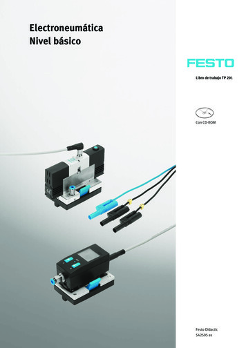
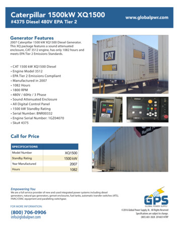
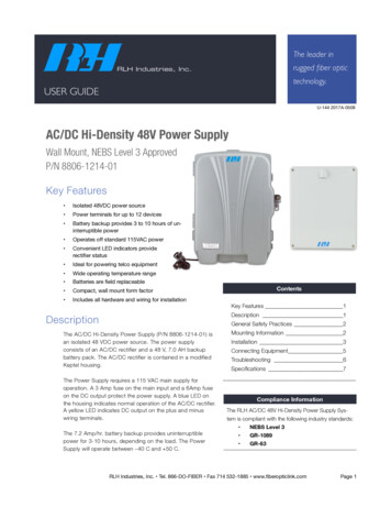
Real application – measured currents and proof of calculation6Real application – measured currents and proof of calculation6.1CMMS-ST with Power Stage supply 48 V6.1.1Equipment- CMMS-ST-C8-7-G2- EMMS-ST-87-S-S-G2- Power stage Supply 48 V DC- Open loopCalculated load current (see example 2, chapter 5.3)IPS,DC 6.4 A6.1.2MeasurementStarting with motor running at constant speed.Load torque increasing with constant slew rate over timeAfter approx. 5.5 s the load torque is higher than the peak torque of the stepper motor and the speed reversals.The peak current at highest load, respectively highest output power reaches approx. 6.5 AFig. 6.1:GraphPage 12 of 18Application Note – Power Supply Stepper – 1.30
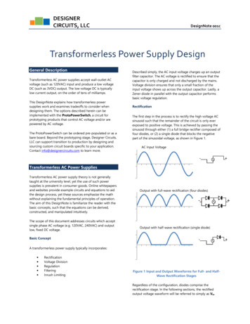
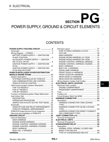
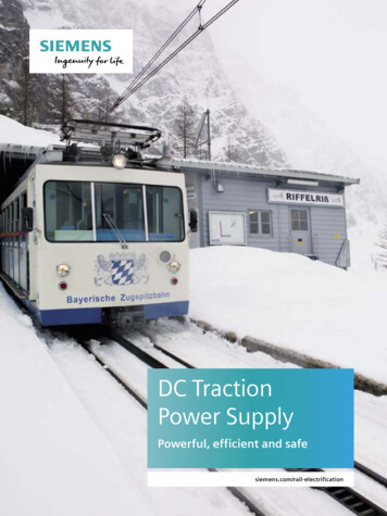
2014 / 11:17:09 /Real application – measured currents and proof of calculation6.2CMMS-ST with Power Stage supply 24 V6.2.1Equipment- CMMS-ST-C8-7-G2- EMMS-ST-87-S-S-G2- Power stage Supply 24 V DC- Open loopCalculated load current (see example 2, chapter 5.3)IPS,DC 6.4 A6.2.2MeasurementStarting with motor running at constant speed.Load torque increasing with constant slew rate over timeAfter approx. 5 s the load torque is higher than the peak torque of the stepper motor and the speed reversalsThe peak current at highest load, respectively highest output power reaches approx. 6.3 Av[Upm]: v -505.12 Upm2000I: I 4.5008 A[A]81500610004500200-500-2-1000-4-1500-60246810t [s]: t 3.78 sFig. 6.2:GraphApplication Note – Power Supply Stepper – 1.30Page 13 of 18
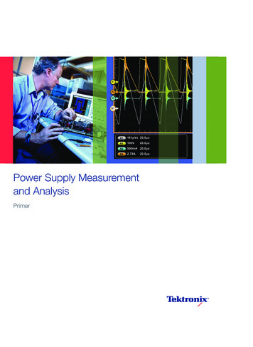
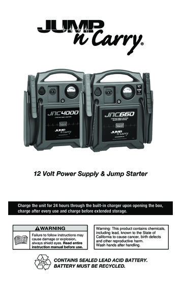
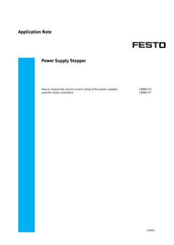
2014 / 15:13:37 /Real application – measured currents and proof of calculation6.3CMMO-ST with Power Stage supply 24 V6.3.1Equipment- CMMO-ST-C5-1-DIO- Power stage Supply 24 V DC- Open loopCalculated load current (see example 2, chapter 5.4)IPS,DC 4.6 A6.3.2MeasurementStarting with motor running at constant speed.Load torque increasing with constant slew rate over timeAfter approx. 5.5 s the load torque is higher than the peak torque of the stepper motor and the speed reversals.The peak current at highest load, respectively highest output power reaches approx. 4.6 2.0-4001.5-6001.0-8000.5-10000.00246810t [s]Fig. 6.3:GraphPage 14 of 18Application Note – Power Supply Stepper – 1.30
Further hints / comments7Further hints / comments7.1Using CMMS-ST and CMMO-ST in open loop modeIf you are using CMMS-ST and CMMO-ST in open loop mode, you need to calculate with the full rated current ofthe motor.7.2Using CMMS-ST and CMMO-ST in closed loop modeIf you are using CMMS-ST and CMMO-ST in closed loop mode, the motor current will be determined by the load.The calculation in chapter 5 is a worst case calculation. Depending on the application, a smaller power supplymight be sufficient, if the load current does not reach the rated current.Maybe it is possible to reduce the setting of the rated current in your application, and then you should re-calculate according to chapter 5.7.3Initial sequence to find the right encoder angle offset for commutationThe Controllers have to find the right encoder offset angle each time the power stage is enabled.CMMS-ST and CMMO-ST detect the encoder angle with the first “Controller enable” after power on. For this function the CMMS-ST uses the boost current. The CMMO-ST uses the rated current. Make sure the used power supply can provide the boost current*0.8 in case of CMMS-ST and rated current *0.8 in case of CMMO-ST.7.4Current peak at power stage enableEach time you enable the power stage of the controller, a small current peak might occur. If this current peaktriggers the overload circuit of your power supply do the following: If you are using several Controllers in onemachine it is useful to enable the controllers one by one or in groups with a small time delay.300ms for CMMS-ST800ms for CMMO-ST.7.4.1Example CMMO–STMachine with 16 axes. The load current of one axis is 1 A, but the rated current is 4.2 A.During the run is approximately 16 A load current necessary, but if all controllers get the “Controller enable” atthe same time, the current can rise up to 16* 4.2 A* 0.8 53.76 A7.5CMMS-ST with 24 VDC load voltageMake sure you have the right settings if only one Power supply 24 VDC is used for control voltage and load voltage, because there may occur higher regenerative voltages during operation.These voltages are limited via the internal brake chopper.Therefore, it is absolutely necessary to parameterize the proper load voltage in theFCT pro
To determine the required power rating for the Power supplies for the logic supply and for the Power stage sup-ply one need to calculate as follows: Logic Power Supply : 1. Calculate the necessary logic Supply current for each CMMS-ST / CMMO-ST in the system (chapter 3) 2. Sum up the