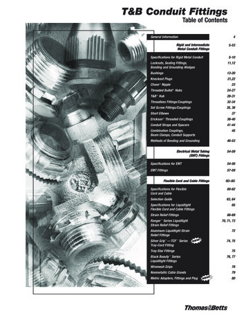
Transcription
HI -TECH ROOF SYSTEMI NSTALLATI ON M ANUAL
Hi-Tech Roof System Installation GuideTABLE OF CONTENTS1.0 GENERAL1.1 Purpose of the Installation Guide1.2 Customer’s Responsibility7.2- 17.2- 12.0 SAFE ROOF INSTALLATION2.1 Erector’s Responsibility2.2 OSHA2.3 Walking & Working on Roof Panels2.4 Handling Roof Materials in Strong Winds7.2- 27.2- 27.2- 27.2- 33.0 CHECKING THE STRUCTURE3.1 Completed and Braced3.2 Lateral Stability3.3 Alignment7.2- 47.2- 47.2- 44.0 RECEIVING & HANDLING ROOF MATERIALS4.1 Equipment for Unloading and Lifting4.2 Material Inventory4.3 Lifting Roof Panel Bundles4.4 Field Storage of Roof Materials4.5 Handling Individual Roof Panels7.2- 57.2- 57.2- 57.2- 67.2- 75.0 ROOF INSTALLATION BASICS5.1 Proper Tools5.2 Equipment List5.3 Sealants5.4 Fasteners5.5 Field Cutting Panels and Flashing7.2- 87.2- 87.2- 87.2- 97.2- 106.0 ROOF PANEL LAYOUT6.1 Sheeting Direction and Modularity6.2 Layout & Checking for Coverage6.3 Appearance Considerations7.2- 117.2- 117.2- 117.0 INSPECTION OF ROOF ASSEMBLY DURING .INSTALLATION7.2- 127.1 Importance of Inspection7.2- 127.2 Inspection List8.0 STANDARD PARTS8.1 General8.2 Standard Parts DetailsTechnical information contained herein is subject to change without notice.7.2- 157.2- 16Page 7.2-iRevision: 1April 2011
Hi-Tech Roof System Installation Guide9.0 ROOF INSTALLATION DETAILS9.1 General9.2 Preparation for Roof Panel Installation9.3 Roof Panel Installation9.4 Termination Panel Installation9.5 Outside Closure Installation9.6 Rake Trim Installation9.7 Rake Transition Installation9.8 Ridge End Cap Installation9.9 High Eave Transition Installation9.10 Eave Gutter InstallationPage 7.2-iiRevision: 1April 20117.2- 207.2- 217.2- 317.2- 547.2- 607.2- 697.2- 757.2- 787.2- 837-2- 87Technical information contained herein is subject to change without notice.
Hi-Tech Roof System Installation Guide1.0 GENERAL1.1 Purpose of the Installation GuideThis installation guide is provided to Rigid GlobalBuildings customers and their erectors as the recommended procedure for the correct assembly of the Hi-TechStanding Seam Roof System.This guide is intended to be used in conjunction with theproject’s erection drawings to help plan and organize theinstallation of the Hi-Tech Standing Seam Roof System.The erection drawings identify the applicable roof conditionsand govern specific part arrangements. The instructions willhelp you identify parts, establish the installation sequence,demonstrate correct assembly, and point out any areas orprocedures requiring special emphasis or attention.This installation guide applies to the standard Hi-TechStanding Seam Roof System. Custom roof conditions,including custom details and instructions, will be coveredby the erection drawings. In case of conflict between thisinstallation guide and the erection drawings, the erectiondrawings will take precedence.1.2 Customer’s ResponsibilityThe customer is responsible for proper installation of theroof in accordance with the erection drawings and this installation guide, and in accordance with good engineeringand construction practices.Rigid Global Buildings does not guarantee and is not liablefor the quality of erection. Rigid Global Buildings is notresponsible for building defects that may be attributed toimproper erection or the negligence of other parties.The customer must take the responsibility for selecting acompetent erector, insist that the work be performed byqualified and experienced standing seam metal roof installers, insist that the erector take time to study and understandthis guide, then assure that the erector correctly follows theguide’s instructions.Clarification concerning the Hi-Tech roof installation shouldbe directed to the Rigid Global Buildings Customer ServiceManager.Contact the Rigid Global Buildings office:Rigid Global Buildings18933 Aldine WestfieldHouston, Texas 77073Phone:(281) 443-9065Toll Free: (888) 467-4443Fax:(281) 443-9064Technical information contained herein is subject to change without notice.Page 7.2-1Revision: 1April 2011
Hi-Tech Roof System Installation Guide2.0 SAFE ROOF INSTALLATION2.1 Erector’s ResponsibilityThe erector of the roof system is responsible for the safeexecution of this installation guide. These instructions areintended to describe the sequence and proper placementof parts. They are not intended to prescribe comprehensivesafety procedures.If the erector cannot safely assemble the roof in accordancewith these instructions, it is the responsibility of the erector to stop the work and contact Rigid Global Buildings todetermine alternate assembly procedures.2.2 OSHAThe Occupational Safety and Health Act (OSHA) has promulgated many regulations applicable to the installation ofthis or any other roof system. These regulations, identifiedas Part 1926, Safety and Health Regulations for Construction, are available from any government bookstore. Theobjective of the OSHA standards is to protect the workerfrom injury or illness. These OSHA regulations should berecognized as job site requirements and be fully compliedwith.Failure to do so may result in substantial fines in the eventof an OSHA inspection. Safe installation practices maybe further defined and made mandatory by state or localordinances.Maintaining good housekeeping on the job site is recognized as being important to both OSHA compliance and tosuccessful job completion.2.3 Walking & Working on Roof PanelsDo not use a roof panel as a working platform. An unsecured panel could collapse under the weight of a personstanding between purlins or at the panel end.Do not walk on the last installed panel run, as the unsecurededge could collapse under a person’s weight. When installing clips or making endlap connections, etc., stand wherethe roof structural will support your weight.A. PLACING PANELS ON THE STRUCTUREDo not place bundles of panels on the roof structure withoutfirst verifying the structure will safely support the concentrated weight of the panels and the weight of the installation crew. Some roof structures may not be designed tosupport the weight of a full panel bundle without additionalstructure support.An approved and safe walking platform should be usedin high traffic areas to prevent the roof panel from beingdeformed, scratched, or scuffed.B. WALKING ON ROOF PANELSLeading RoofPanelAssembledSidelap (Typ.)CORRECTStep ONLY on secured roof panelsLeading AUTION — INCORRECTDO NOT step on leading (unsecured) roof panel.Page 7.2-2Revision: 1April 2011Technical information contained herein is subject to change without notice.
Hi-Tech Roof System Installation Guide2.0 SAFE ROOF INSTALLATION2.3 Walking & Working on Roof Panels (Continued)C. SAFETY EQUIPMENTThe use of safety equipment for the roof panel installationis recommended at all times during the installation process.However, when using lanyards, ensure that the clasp, belthooks and wire cables are covered in such a manner thatthey will not scratch the panel surface if accidentally draggedalong the panel.D. CREW SIZEThe length of the individual roof panels should be considered when determining the crew size. It is recommendedthat under normal conditions, there be one person for everyten feet of panel length, plus one.E. PANEL OVERHANGDo not stand on the end of unsupported (cantilevered) panels at the eave or ridge. Standing on the cantilever portionmay result in panel collapse.F. POINT LOADSWhen properly supported by the structural, panels aredesigned to support uniform loads, which are evenly distributed over the panel surfaces. Point loads that occur insmall or concentrated areas, such as heavy equipment,ladder or platform feet, etc., may cause panel deformationor even panel collapse.G. SLICK SURFACESPanel surfaces and structural steel surfaces are hard,smooth, and nonabsorbent, which causes these surfaces tobe very slick when wet or covered with snow or ice. Evenblowing sand or heavy dust can make these surfaces difficult to walk on without slipping.Unpainted panel surfaces are often coated with oil to accommodate the panel-fabrication process. Although designedto wash away or evaporate during normal weather, the oilon new panels can be extremely slick, especially duringperiods of light rain or dew.Caution must be exercised to prevent slipping and fallingonto the roof surface or even sliding off the roof. Non-slipfootwear is a necessity and non-slip working platforms arerecommended.H. ELECTRICAL CONDUCTANCEMetal panels are excellent electrical conductors. A commoncause of injury is the contact of metal panels with powerlines during handling and installation. The location of allpower lines must be noted and, if possible, flagged. Theinstallation process must be routed to avoid accidentalcontact with all power lines and high voltage services andequipment. All tools and power cords must be properlyinsulated and grounded and the use of approved groundfault circuit breakers is recommended.I. FALSE SECURITY OF INSULATIONBlanket and board insulation blocks the installer’s view ofthe ground below the roof. Serious injury can occur whenthe installer gets a false sense of security because he cannot see the ground and steps through the insulation.J. SHARP EDGESSome edges of panels and flashing are razor sharp andcan cause severe cuts if proper protective hand gear is notworn. Be careful not to injure others while moving panelsand flashing.2.4. Handling Roof Materials in Strong WindsDo not attempt to move panels in strong winds. Windpressure can easily cause a man to lose balance and fall.Strong wind uplift on a panel can lift the weight of the mancarrying the panel.Secure stacks of panels with banding or tie-downs, sowind will not blow the panels off the roof. Clamp individualunsecured panels to the roof purlins. Clamp or block panelbundles and accessory crates to prevent them from slidingdown the roof slope.Loose, wind borne panels are very dangerous and cancause severe injury and damage.Technical information contained herein is subject to change without notice.Page 7.2-3Revision: 1April 2011
Hi-Tech Roof System Installation Guide3.0 CHECKING THE STRUCTURE3.1 Completed and BracedBefore placing materials and workers on the roof structure tostart roof installation, it must be confirmed that the structureis designed to accommodate the material and erection loadsas well as the appropriate live loads and wind uplift loads.It also must be determined that the structure is completeand structurally sound with all structural connections andbracing in place and secure.3.2 Lateral StabilityThe sliding clip method of attaching the roof panels to theroof purlins provides only limited lateral stability and diaphragm bracing to the roof purlins.Before placing materials on the roof and starting the roofinstallation, confirm that the necessary roof bracing andsag angles, strapping or bridging is in place and secured.3.3 AlignmentPrior to installation, roof purlins should be checked foroverall dimensions and evenness of plane. The roof purlinsshould also be checked to verify the roof system could beinstalled without interference. Also, roof purlins nearest thepanel endlaps, ridge or high eave should be checked for correct location to properly accommodate the roof components.rake straightness error does not exceed the roof system’stolerance, the structure length should be measured fromrake line to rake line at each eave, at the ridge and at eachpoint where there is a significant error or change in rakestraightness (this usually occurs at an end rafter splice).A. TOLERANCESTo assure the roof system’s correct fit-up and designedweather tightness, the structure must be aligned within thefollowing tolerances:B. MEASURINGStructure length and width may be measured with a steelmeasuring tape from the face of the eave or rake memberto the face of the opposite eave or rake member. The measuring tape must be parallel to the relative eave or rake lineand must be stretched taut.Out of Square — The roof system can only accommodate1/4” of saw-tooth of the roof panel ends at the eave, ridgeand panel splices. This means the allowable out of squareof the rake line relative to the eave line and ridge line is 1/4”for each 40’ of rake run.Eave and rake straightness may be determined by measuring deviations from a string line, which is stretched tautalong the eave or rake line.Structure Width and Eave Straightness — The roof system is designed to accommodate 2” of overall structurewidth error, or 1” of eave straightness error at each eave.To assure that the accumulation of the structure width error and eave straightness error does not exceed the roofsystem’s tolerance, the structure width should be measuredfrom eave line to eave line at each rake, at the first frameline from each rake and at each point where there is a significant error or change in eave straightness (this usuallyoccurs at a frame line or at a wind column).Structure Length and Rake Straightness — The roofsystem is designed to accommodate 2” of overall structurelength error, or 1” of rake straightness error at each rake.C. AESTHETIC ACCEPTANCEAlthough these structure alignment tolerances will allowfor reasonable roof component fit-up and ease of installation, the extremes of these tolerances may be aestheticallyobjectionable and should be confirmed with the customerbefore starting the roof installation.D. CORRECTIONSAny structure alignment error, which exceeds the abovestated tolerances, must be corrected before roof installationcan begin. If it is decided that the structure alignment errorscannot be corrected, alternate roof details may have to bedeveloped. The alternate details may require additionalmaterials, modified parts (with additional cost, fabricationand delivery time) and additional installation time. RigidGlobal Buildings cannot assure the performance of suchalternate details.To assure that the accumulation of structure length error andPage 7.2-4Revision: 1April 2011Technical information contained herein is subject to change without notice.
Hi-Tech Roof System Installation Guide4.0 RECEIVING & HANDLING ROOF MATERIALS4.1 Material InventoryYour material is carefully inspected and crated before leaving the plant and accepted by the transportation companyas being complete and in satisfactory condition. It is thecarrier’s responsibility to deliver the shipment intact. It isthe consignee’s responsibility to inspect the shipment fordamages and shortages when it is delivered.Conducting a material inventory at the time of delivery isessential. By conducting the materials inventory, the erector is able to identify any material shortage or damage andavoid stopping installation later because of such shortageor damage.It is imperative that any shortages or damage of the delivered materials be noted at once and clearly marked on thebill of lading before signature of acceptance. Notify RigidGlobal Buildings immediately of any conflicts. Rigid GlobalBuildings will not be responsible for shortages or damagesunless they are noted on the bill of lading.In the case of packaged components (such as clips, fasteners and sealants, etc.), the quantities are marked on theircontainer and should be checked against the bill of materials. Rigid Global Buildings must be notified of any shortages or concealed damage within 5 days of delivery.4.2 Equipment For Unloading and LiftingHoisting equipment is necessary to unload and positionthe panels and accessory crates for site storage and installation. The equipment must have sufficient capacity andreach to place the material where it is required for efficientinstallation.to assure correct sling spacing and uniform lifting. Thespreader bar must be large enough to handle the maximumpanel bundle weight and length.A forklift is handy for unloading and placing shorter paneland accessory crates.Slings will be required to minimize panel damage. The recommended slings are nylon straps of 6” minimum width andof sufficient length to accommodate the panel bundle girth.A spreader bar will be required for the longer panel crates4.3 Lifting Roof Panel BundlesUnder normal conditions, panel crates less than 35’ longcan be lifted with two slings spaced at third points. Panelcrates longer than 35’ can be lifted with three slings locatedat quarter points using a spreader bar to achieve correctsling spacing for uniform lift.necessary to control the load during lifting, especially ifoperating in the wind.Panel crates less than 25’ long may be lifted with a forkliftonly if the forks are spread at least 5’ apart and blocking isused to prevent panel damage by the forks.Slings should be located under the cross boards. Loadsshould always be checked for secure hook-up, properbalance, and lift clearance. Tag lines should be used ifPanelBundleFork LiftSpreaderWeb SlingsForkBladesPanel BundleEqua5’MinimumlSpacesTechnical information contained herein is subject to change without notice.Page 7.2-5Revision: 1April 2011
Hi-Tech Roof System Installation Guide4.0 RECEIVING & HANDLING ROOF MATERIALS4.4 Field Storage of Roof MaterialsUpon acceptance of the shipment, the customer or hisrepresentative is responsible for proper handling storageand security of the roof materials. Rigid Global Buildingsis not liable for damage or loss of materials at the job site.The roof panel bundles should be stored on the job site inaccordance with the following recommendations:a. Store panels in a protected area, out of standingwater and drifting snow, etc.b. Elevate panels with blocking to allow air circulationunder the bundle.c. Slope panels for drainage of moisture from thepanels.d. As necessary, cover panels with waterproof tarp,allowing for air circulation (do not wrap tarp underpanel crate or restrict air movement).e. Inspect panels daily for moisture accumulation.f. If panel bundles contain moisture, the panels shouldbe dried and re-stacked. Use care in re-stacking toavoid damage to panels.g. Opened or re-stacked panel bundles should besecured to prevent wind damage.When moving panel bundles, extreme caution should betaken to prevent damage to the panel edges. Uncratedpanels should be supported at each end and at 8’ spaces.All bundles or loose panels on the roof should be bandedto the roof purlins at the end of each workday. On steeproofs, provisions should be taken to prevent panels andpanel crates from sliding off the roof. Be sure to set panelbundles on the roof in the proper direction for the installation sequence.Trim and accessories should be stored in a secure areaand protected from damage, weather, and theft. Fasteners,sealants, closures, etc. should be stored out of the weatherand protected from contamination.Panel BundleBlockingStack blocking so bundleis sloped for drainagePage 7.2-6Revision: 1April 2011Technical information contained herein is subject to change without notice.
Hi-Tech Roof System Installation Guide4.0 RECEIVING & HANDLING ROOF MATERIALS4.5 Handling Individual Roof PanelsTo lift individual panels, lift one side of the panel by the seamletting it hang naturally to prevent buckling. Pick-up pointsshould not be more than 10’ apart. Do not pick-up panelsby the ends only, or in a flat position.If the individual panels are to be lifted to the roof by handline, the common method is to use the vice grip “C” clamps.Position the clamps on the flat of the panel, as close as possible to one edge so the panel is lifted in a vertical position.The jaws of the vice grips must be padded to prevent damage to the panel surface. The clamps should be uniformlyspaced, no more than 10’ apart and the hand lines mustbe pulled in unison so that uneven lifting does not bucklethe panel. Be sure the clamps are tight on the panel andthe line is secure to prevent dropping the panel, which canresult in personal injury and property damage.10’ Maximum10’ MaximumRoof PanelTechnical information contained herein is subject to change without notice.Page 7.2-7Revision: 1April 2011
Hi-Tech Roof System Installation Guide5.0 ROOF INSTALLATION BASICS5.1 Proper ToolsBefore starting paneling, be sure that the proper equipment and tools are on hand. The tools must be in goodoperating condition and operators should adhere to safetyprecautions at all times.Improperly operating tools, too few tools, inadequate powersource, or other equipment deficiencies slow down the installation process. The cost of inefficient working is usuallygreater than the cost of providing good equipment.5.2 Equipment ListThe following tools and equipment should be consideredfor efficient installation of the Hi-Tech standing seam panel.Actual tools and equipment required may vary due to variations in building type and construction.This list should not be interpreted as a limitation to yourinventory of installation equipment.*Hi-Tech Motorized Seaming Machine*ESE #812 Hand Seaming ToolScrew Guns — Designed for use with self-drilling screwsSocket Extensions — 6” extension for screw gunHex Socket Heads — 5/16” and 3/8”, magneticDrill Motor — 1/4” capacityDrill Bits — AssortmentSheet Metal Cutter — or power shears or nibbler“C” Clamps — vise grip typePop Rivet Tool — 1/8” capacitySheet Metal Shears — left and right cutHack Saw — with metal cutting bladeGrease gunPunchSteel Measuring Tape — 12’, 50’, 100’Nylon String LinesChalk LineBroomsMarking PenCaulk Guns — for 1/10 gallon sealant tubesPower Source and Extension Cords — capable of handlingthe total equipment requirements, including 20-ampseamer machine, without power drop due to extensioncord length.*These tools are specifically designed for the Hi-Tech RoofPanel and are available from the Rigid Global Buildings5.3 SealantsA. TEMPERATURE EFFECTSTemperature extremes must be considered during installation of the roof due to the sensitivity of sealants. Therecommended installation temperature range is 20º F to120º F. At colder temperatures, the sealant stiffens resultingin loss of adhesion and compressibility. At hotter temperatures, the sealant becomes too soft for practical handling.On cold but sunny days, the panel’s surface may becomewarm enough to accept the application of a heated sealanteven though the air temperature is below 20º F.When overnight temperatures fall below freezing, the sealant should be stored in a heated room so it will be warmenough to use the following day. On hot days, the sealantcartons should be stored off the roof in a cool and shadedarea. While on the roof, sealant rolls should be kept shadeduntil actual use.In very cold weather, it is recommended that the fastenersbe tightened slowly and only tight enough that the sealantis in full contact with the panel or flashing. Then on the nextsunny day, complete the tightening process after the sunwarms the panel and flashing surfaces.Page 7.2-8Revision: 1April 2011B. CONTAMINATIONTo assure proper adhesion and sealing, the sealant musthave complete contact with adjoining surfaces Contaminants such as water, oil, dirt and dust prevent such contact.The panel and flashing surfaces must be dry and thoroughlycleaned of all contaminants. Before applying tape sealant,the sealant should be checked for contaminants. If thesealant surfaces are contaminated, it must not be used.During cool weather, condensation or light mist can accumulate on the panel and flashing surface and not be easilynoticed. It is recommended that sealants always be keptunder protective cover and that the panel and flashing surfaces be wiped dry immediately before installation.Tape sealant is provided with a protective paper to reducecontamination. Incomplete removal of the protective paperwill prevent the sealant’s adhesion to the panel or flashingsurfaces. Always check that the protective paper is completely removed. Do not remove the protective paper untilimmediately before the panel or flashing is installed overthe sealant.Technical information contained herein is subject to change without notice.
Hi-Tech Roof System Installation Guide5.0 ROOF INSTALLATION BASICS5.3 Sealants (Continued)C. COMPRESSIONTo assure proper adhesion and seal, the tape sealant mustbe compressed between the panel and flashing surfaceswith firm and uniform pressure. In most cases, the requiredpressure is applied by the clamping action of screws pullingthe adjoining surfaces together. However, the tape sealant’sresistance to pressure becomes greater in cold weather.During cold weather, the fasteners must be tightened slowlyto allow the sealant time to compress. If the fasteners aretightened too fast, the fastener may strip out before thesealant compresses adequately, or the panel or flash maydeform in the immediate area of the fastener, leaving therest of the sealant insufficiently compressed.D. INSIDE CORNERSAn inside radius, such as where the panel flat meets a rib, isusually the most critical area to seal. A common mistake forthe installer, is to bridge the sealant across the inside radius.When the lapping panel or flashing is pushed into place,the bridged sealant is stretched and thinned. The sealantmay then be too thin to adequately seal this critical area.When tape sealant is applied at an inside radius, it is recommended that the sealant be folded back on itself, thenpush the sealant fold into the radius.VoidCaution:Do not allow thesealant to bridgeacross inside radiicreating voidsVoidEndlapSealantFold the sealantand push the foldinto the radiusEndlapSealantRoof PanelRoof PanelVoidCORRECTINCORRECT5.4 FastenersA. SCREW GUNUse torque control screw guns for driving self-drillingscrews. 2000-2500 RPM screw gun speeds are necessary to attain efficient drilling speeds. High tool amperage(4 to 7 AMP) is required to achieve the proper torque forsecure fastening.When the socket is removed from the sealant, most of thedrill shavings will remain embedded in the sealant therebycleaning the socket. This process should be repeated asoften as needed to keep the socket clear of drill shavings.B. SOCKETSUse good quality magnetic sockets. Good fitting sockets reduce wobble and stripping of the screw heads, especially thealloy and capped heads. They also minimize objectionablepaint chipping and scuffing on colored screws and minimizedamage to the protective coating on unpainted screws.C. SOCKET EXTENSIONA 4” or 6” socket extension is recommended for installingthe panel clip screws. With the extension the screw can bedriven straight down without tilting the screw gun to clearthe panel or clip. Since socket extensions are slow to wearout, it is usually more cost effective to purchase socketextensions and good quality sockets rather than purchasesockets with built-in extensions.Magnetic sockets collect drill shavings, which will build upand eventually prevent the socket from seating properly onthe screw heads. One method of removing the drill shavings is to roll up a ball of tape sealant and push the socketinto the sealant.D. INSTALLATIONBefore starting the screw, the materials to be joined must bepressed together with foot or hand pressure. The pressuremust be maintained until the screw has drilled through allthe materials and the threads have engaged.Technical information contained herein is subject to change without notice.Page 7.2-9Revision: 1April 2011
Hi-Tech Roof System Installation Guide5.0 ROOF INSTALLATION BASICS5.4 Fasteners (Continued)Most self-drilling screws require 20 pounds of pressure tomaintain the drilling action and to start the thread cuttingaction. Also, applying such pressure before starting thescrew gun will usually prevent tip walking or wandering. Iftoo little pressure is applied, the drill point may not cut intothe metal and the point will heat up and become dull. If thepressure is too heavy, the bottom material may be deflectedaway, causing a standoff condition, or the drill tip may bebroken or split. Screws must be held perpendicular to thepanel or flashing surface during starting and driving.For proper seating of the fastener-sealing washer, the panelor flashing surface must be clean and drill shavings must beremoved from under washers before seating. The fastenermust be driven perpendicular to the panel surface so thatthe washer can seat level without warping or cupping.The fastener should be driven tight enough to uniformlycompress the washer but not so tight that the washer splitsor rolls out from under it’s metal dome. The recommendedprocedure is to tighten the fastener until the sealing washerjust starts to visually bulge from under the metal dome.As a good installation practice, all roof installers shouldcarry approved oversized screws. Upon stripping or breaking a screw, the screw must be immediately removed andreplaced with the appropriate oversized screw. Do not deferthe screw replacement to be remembered and fixed later,or to be found by the clean-up crew. The majority of suchscrews will be overlooked until the customer complains ofleakage.Do not over drive screws. Over driving can strip the threadsand/or damage the sealing washer. Use screw gun withtorque control set to function properly for the combinationof fastener size, hole size and material thickness.5.5 Field Cutting Panels and FlashingA. ABRASIVE SAW PROBLEMSAbrasive saws (circular saws with friction disks) are notrecommended for cutting roof panels or flashing. Abrasivesaws create high heat that may burn away the protectivecladding from the panel edge, causing the edge to rust.Also, abrasive saw dust contains fine, hot steel particles,which accumulate on panel and flashing surfaces wherethey rust and can cause staining and rusting of thosesurfaces.Rust caused by abrasive saw damage or abrasive dustparticles may be excluded from warranty claims.B. SHEARING METHODSIt is recommended that panels and flashing be cut withshears to provide a clean, undamaged cut. On shear cutedges, the protective cladding extends to the edge of the cutand is often wiped over the edge to further protect the basemetal. Whenever possible, fit the material so that the factory cut edge is exposed and the field cut edge is covered.Pa
Clarifi cation concerning the Hi-Tech roof installation should be directed to the Rigid Global Buildings Customer Service Manager. Contact the Rigid Global Buildings offi ce: Rigid Global Buildings 18933 Aldine West fi eld Houston, Texas 77073 Phone: (281) 443-9065 Toll Free: (888) 467-4443 Fax: (281) 443-9064