Transcription
Report CE/ST 36report submitted to American Institute of Steel ConstructionEffects of Slab Post-tensioning onSupporting Steel BeamsBhavna Sharma, M.Sc.Kent A. Harries, Ph.D., FACI, P.Eng.March 2007structural engineering and mechanicsWatkins-Haggart Structural Engineering Laboratory
Effects of Slab Post-tensioning on Supporting Steel BeamsBhavna Sharma and Kent A. Harries, Ph.D., FACI, P.Eng.University of PittsburghDepartment of Civil and Environmental EngineeringPittsburgh PA 15261AcknowledgementsThis study was carried out with support from the American Institute of Steel Construction (AISC). In this regard, theauthors wish to acknowledge Tom Schalfly, Bill Pascoli, John Cross and Charles Carter. Charles Churches Sr. ofChurches Engineering, Washington PA, is the EOR for the project. His support and the information he provided isgratefully acknowledged. Eric Campbell of Ionadi Construction, Pittsburgh PA, was the site supervisor; his assistancewas invaluable to the study. The building is owned by Real Estate Enterprises, Pittsburgh PA; Kai Olander isacknowledged for providing access to the site and test structure. University of Pittsburgh graduate andundergraduate students Keith Coogler, Patrick Minnaugh, Derek Mitch, Mark Beacraft, Louis Gualtieri and LisaAbraham assisted in various aspects of instrumentation and data acquisition. The findings of this report do notnecessarily reflect the opinions of those acknowledged above.This research was sponsored by the American Institute of Steel Construction. The opinions, findings and conclusionsexpressed in this report are those of the authors and not necessarily those of AISC or The University of Pittsburgh. Thisreport does not comprise a standard, specification or regulation.Effects of Slab Post-tensioning on Supporting Steel BeamsUniversity of Pittsburgh Structural Engineering and Mechanics Report CE/ST 35page 1 of 40
this page intentionally left blankEffects of Slab Post-tensioning on Supporting Steel BeamsUniversity of Pittsburgh Structural Engineering and Mechanics Report CE/ST 35page 2 of 40
Table of Contents1. Preamble.51.1 Objective.52. Current Practice and Literature Review .53. Test Structure – 450 Melwood Avenue, Pittsburgh PA.53.1 Structural Steel .103.2 Concrete .103.3 Post Tensioning Strand .113.4 Mild Reinforcement.114. Instrumentation.115. Test Program.146. Test Results.176.1 Post-Tensioning Operation – November 27, 2006.216.2 Live Load Tests .236.2.1. “Audi” Test – December 30, 2006 .236.2.2. “Two Vehicle” Test – January 12, 2007 .256.3 Gage Integrity .257. Discussion of Test Results .277.1 Effective Width of Slab.277.1.1 Effective width while formwork is in place.277.1.2 Code prescribed effective width .277.2 Composite Section Properties .287.3 Predicted Behavior .287.4 Predicted versus Observed Behavior .297.5 Post-tension-induced stresses.297.5.1 Post-tensioning operation.297.5.1.1 Rigorous Analysis of post-tensioning operation .307.5.2 Release of formwork .327.6 Summary of Procedure for Assessing PT-induced Stresses .327.6.1 PT pulled while slab shored.327.6.2 PT pulled while slab is unshored .337.6.3 Non-composite slab.337.6.4 AISC Design Guide 18 Figure 3.12 misconception .338. Summary and Conclusions.359. Cited References.36Appendix A – Observed Strain Data.37Appendix B – Concrete Shrinkage and Cracking of Slab.38B.1 Restraint of Concrete Shrinkage Causing Cracks .38B.2 Plastic Shrinkage Cracking.39Effects of Slab Post-tensioning on Supporting Steel BeamsUniversity of Pittsburgh Structural Engineering and Mechanics Report CE/ST 35page 3 of 40
List of FiguresFigure 3.1 450 Melwood Avenue, Pittsburgh PA.6Figure 3.2 Completed parking structure at 450 Melwood Ave .6Figure 3.3 Structural steel framing plan .7Figure 3.4 Steel superstructure.8Figure 3.5 PT tendon and reinforcing steel plan .9Figure 3.6 Reinforcing bar and strand layout prior to concrete placement.10Figure 4.1 Strain gage layout .11Figure 4.2 Strain gage installation.12Figure 4.3 Installations of formwork shores near and directly on top of strain gages.13Figure 4.4 Vishay P3 4-channel strain gage indicator.13Figure 5.1 Pittsburgh ambient hourly temperatures .15Figure 5.2 Placing concrete: November 22, 2006 .16Figure 5.3 Pulling the PT strand: November 27, 2006 .16Figure 5.4 Shoring condition at Beam B: December 23, 2006 .16Figure 5.5 Taking readings: December 14 through 19, 2006.16Figure 6.1(a) Strain profiles for Beam B.18Figure 6.1(b) Strain profiles for Beam C .19Figure 6.1(c) Strain profiles for Beam D.20Figure 6.2 Observed strains during post-tensioning operation.23Figure 6.3 Live load test: December 30, 2006 .24Figure 6.4 Live load test: January 12, 2007 .26Figure 7.1 Location of form shores at Beam B.27Figure 7.2 Modeling shored beam as beam on elastic foundations .31Figure 7.3 PT-induced stresses .33Figure 7.4 Noncomposite and incorrect PT-induced stress distribution .34Figure B.1 Predicted shrinkage strains and estimated cracking strains.39Figure B.2 Cumulative bleed and evaporation as function of time .39Figure B.3 Evaporation rate nomograph from ACI 308.1 .40List of TablesTable 3.1 Concrete test results .10Table 5.1 Test Program Milestones .14Table 6.1 Results of live load test: January 12, 2007.25Table 7.1 Effective width calculations .27Table 7.2 Composite section properties.28Table 7.3 Predicted steel stress and strain behavior .28Table 7.4 Comparison of observed and predicted behavior at midspan of Beam D .29Effects of Slab Post-tensioning on Supporting Steel BeamsUniversity of Pittsburgh Structural Engineering and Mechanics Report CE/ST 35page 4 of 40
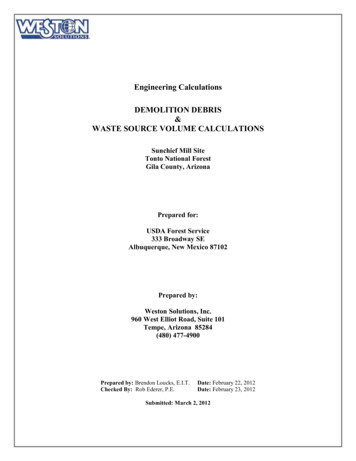
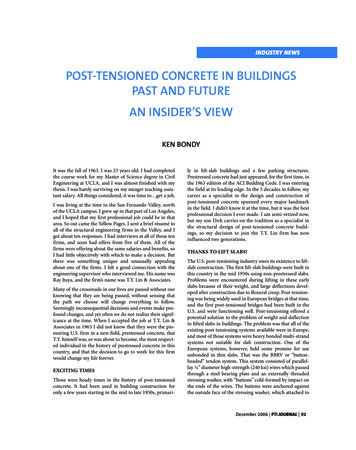
1. PreambleAISC Design Guide 18, Steel Framed Open-Deck Parking Deck Structures (Churches et al. 2003), discusses the useof cast-in-place post tensioned slabs in steel framed parking structures. In Section 3.3.2.1, the authors reflect on themanner in which the post-tensioning force is carried by the supporting beam: in a non composite or compositemanner. They conclude that the post-tensioning force is carried almost entirely in a composite manner (minus effectsof shrinkage and elastic shortening). This conclusion is based on results of unpublished research (as reported) and iscorroborated by earlier design guidance provided by Bakota (1988).1.1 ObjectiveThe objective of this field study is to quantitatively assess the effect that slab post-tensioning forces have on theirsupporting steel members.2. Current Practice and Literature ReviewCast-in-place post-tensioned concrete slabs on steel girders are an attractive alternative for parking structures. Theuse of post-tensioned slabs permits somewhat longer spans to be achieved but primarily enhances the durability ofthe slab system, affecting superior crack control. Investigation of the effects of the post-tensioning stress on thecomposite behavior of the beams has been explored but not published. Current practice, as promulgated in AISCDesign Guide 18, Steel Framed Open-Deck Parking Deck Structures (Churches et al. 2003) assumes that thecomposite beams experience a small amount of compressive stress from the post-tensioning of the slab along thelength of the beam. Design Guide 18 notes that unpublished testing by Mulach Steel Corporation demonstrated astress increase of 3% in the composite beams under dead load conditions.Bakota (1988) explores the design of a post-tensioned parking deck and analyzes the effects of post-tension stresseson the composite beam. The author notes various design criteria for a post-tensioned deck and that an effective posttension stress of 100 psi in the transverse shrinkage and temperature direction reduces the effects of the posttensioning parallel to the beam. Bakota presents equations to determine the long-term stresses and deflections. Heconcludes that the post-tension forces in the deck create long-term beam and slab stresses due to differential volumechanges.Steel framed parking structures, in general, where introduced in the literature in the 1960’s (Sontag 1970; “New”1974). Frequent references and case studies appear in the literature through today: in North America, typicallyappearing in Modern Steel Construction; in Europe, in Acier-Stahl-Steel; and elsewhere including a number ofreferences in the South African Journal Steel Construction. In addition to Design Guide 18, AISC promulgatesInnovative Solution in Steel: Open Deck Parking Structures (Troup and Cross 2003). Available references in theliterature primarily address precast concrete decks on steel frames (e.g.: Simon 2001; Englot and Davidson 2001). Areview of available literature revealed no additional publications relating specifically to cast-in-place post-tensionedconcrete decks on steel frames.3. Test Structure – 450 Melwood Avenue, Pittsburgh PAThe test structure reported in this study is a single story steel parking structure having a post-tensioned compositeconcrete deck. The structure is located behind 450 Melwood Avenue in the North Oakland area of Pittsburgh (Figure3.1). The structure, shown complete in Figure 3.2, is a single story steel frame over a slab on-grade. Parking isprovided on both levels although there is no connecting ramp. Separate entrances are provided for the grade anddeck parking.Effects of Slab Post-tensioning on Supporting Steel BeamsUniversity of Pittsburgh Structural Engineering and Mechanics Report CE/ST 35page 5 of 40
450 Melwood Ave.University of PittsburghFigure 3.1 450 Melwood Avenue, Pittsburgh PA.Overall view of 11 bay parking structure looking West from across railway right-of-way.Beams A & BBeams B, C & DInterior of parking structure.Exterior of parking structure at Beams A and B.Figure 3.2 Completed parking structure at 450 Melwood Ave.Effects of Slab Post-tensioning on Supporting Steel BeamsUniversity of Pittsburgh Structural Engineering and Mechanics Report CE/ST 35page 6 of 40
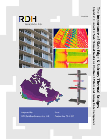
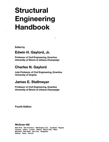
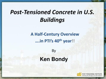
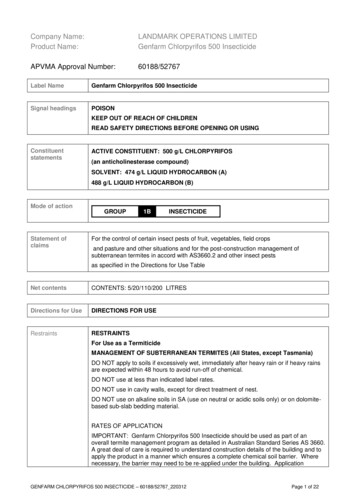
As shown in Figure 3.3, the structure has eleven bays (ten measuring 20’-0” and the first measuring 15’ 0”) in the N-Sdirection and two bays in the E-W direction: bay 1-2 measuring 45’-2” and bay 2-3 measuring 35’-2”. There is a 10’cantilever beyond column line 3. All columns are W12x65 and the beams spanning bay 1-2 are W24x76 at Beams Cand D and W24x68 at Beam B. Where beams frame into girders, a simple shear connection is provided (Figure 3.4,lower left). Beams that frame into columns (all strong axis, in this case) are provided with angles at both flangesresulting in a partially-restrained connection (Figure 3.4, lower right). The beams considered in this study span bay 12 at column lines B, C and D. These beams will be referred to as Beams B, C and D, respectively as indicated inFigure 3.3.1245' 2"edge of concrete1' 6"335' 2"2' 6"15' 0"W16x31AW24x68B20' 0"W30x108W36x135Beam BW24x76CW24x7620' 0"W16x26Beam DW12x65 (typ.)W12x65 (typ.)W24x7611 bays totalE20' 0"W16x31 (typ,)Beam CDN10' 0"Figure 3.3 Structural steel framing plan.The cast-in-place concrete deck is a 6” post-tensioned concrete slab. Reinforcing details of the deck are shown inFigure 3.5 and views of the deck prior to concrete placement is shown in Figure 3.6. Single, double and triple strandsare arranged as shown in Figure 3.5. The concrete stress due to initial post tensioning is 330 psi in the N-S directionand 168 psi in the E-W direction. Mild steel is arranged primarily for crack control as indicated in Figure 3.5.Additionally, as shown in Figure 3.6, 5/8” x 3” shear studs are provided along all beams in bay 1-2 at a spacing of10”.Effects of Slab Post-tensioning on Supporting Steel BeamsUniversity of Pittsburgh Structural Engineering and Mechanics Report CE/ST 35page 7 of 40
Figure 3.4 Steel superstructure.Effects of Slab Post-tensioning on Supporting Steel BeamsUniversity of Pittsburgh Structural Engineering and Mechanics Report CE/ST 35page 8 of 40
121245' 2"45' 2"15' 0"A20' 0"B41" (typ.)36" (typ.)20' 0"CN20' 0"8 1/2" strands/bayDE10' long #5 bars (typ.)#5 bar along beam (typ.)37 1/2" strands/baypost-tensioning layoutmild-reinforcement layoutFigure 3.5 PT tendon and reinforcing steel plan.Effects of Slab Post-tensioning on Supporting Steel BeamsUniversity of Pittsburgh Structural Engineering and Mechanics Report CE/ST 35page 9 of 40
Figure 3.6 Reinforcing bar and strand layout prior to concrete placement (November 21, 2006).3.1 Structural SteelAll structural steel considered in this study are ASTM A992 Grade 50 members. No material tests were conducted onthis steel.3.2 ConcreteThe concrete in bay 1-2 was placed beginning at 7 am on November 22, 2006. The concreting in the vicinity of thetest beams was completed by 8:30 am. The specified concrete compressive strength was 5000 psi. Both theUniversity of Pittsburgh team and the contractor placed test cylinders. Table 3.1 provides concrete material strengthreported by both laboratories.Test reported by contractor labUniversity of PittsburghUniversity of Pittsburgh1Table 3.1 Concrete test resultsage of concreteconcrete compressive strength5 days3450 psi (std dev 570 psi)15 days2010 psi (std dev 752 psi)28 days5070 psi (std dev 11 psi)approximate values, not verified by authorsFollowing placement on November 22, 2006, the ambient temperature reported for Pittsburgh is given in Figure 5.1(top). As a rule-of-thumb, the temperature needs to exceed 45oF otherwise curing is retarded. Curing is arrestedwhen the temperature falls below 32oF. The cylinders tested by the University of Pittsburgh were left on site inambient conditions until the morning of November 27. The contractor cylinders, on the other hand were removedEffects of Slab Post-tensioning on Supporting Steel BeamsUniversity of Pittsburgh Structural Engineering and Mechanics Report CE/ST 35page 10 of 40
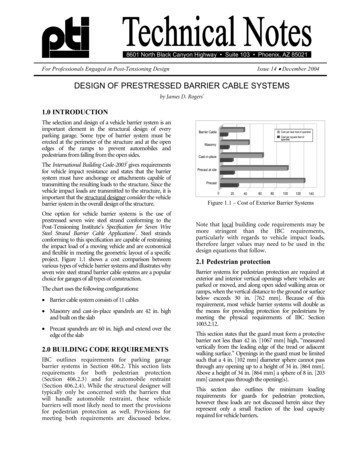
from the site November 24. It is believed that these latter cylinders were maintained in a more controlled environmentuntil tested on November 27. This series of events explains the discrepancy in concrete material strengths obtainedat 5 day testing. As no curing mats were used, it is proposed that the University of Pittsburgh results are morerepresentative of the in situ concrete properties.3.3 Post Tensioning StrandAll post tensioning strand used in the deck was ½” 270 ksi seven wire prestressing strand (Aps 0.153 in2). Thestrand was enclosed in a greased plastic sheath. No material tests were conducted on this steel. The post-tensioningoperation is described in Section 6.1.3.4 Mild ReinforcementAll mild reinforcement in the deck is #5 epoxy coated reinforcing bar having a nominal yield strength of fy 60 ksi. Nomaterial tests were conducted on this steel. The mild steel was provided only for crack control and is not sufficient toaffect the deck structural behavior.4. InstrumentationElectrical resistance strain gages were used to determine strain in Beams B, C and D. As shown in Figure 4.1, gageswere located at five sections along beams B and D and at three sections along Beam C1. At each section, threegages were provided as shown in Figure 4.2: one on the bottom of the top flange, one on the top of the bottom flangeand one at the midheight of the web. Gages are designated by their beam designation and the number 1 through 15as shown in Figure 4.1 (for example, gage D8 is the web midheight gage at midspan of Beam D) All gages wereoriented longitudinally to capture flexure-induced strains. The flange gages were located 1.5” from the face of theweb so as to avoid both the K-region fillet and the lapping of the deck form (Figure 4.2).center linegage locations on section shown in Figure 4.248 in.West1 (top flange)2 (mid web)3 (bottom flange)face of column or beam48 in.45648 in.789101311141215gages 10-15 not installed on Beam C48 in.EastFigure 4.1 Strain gage layout.1failure of the strain gage welder did not allow the final two sections (gages 10-15) on Beam C to be instrumented.Effects of Slab Post-tensioning on Supporting Steel BeamsUniversity of Pittsburgh Structural Engineering and Mechanics Report CE/ST 35page 11 of 40
Figure 4.2 Strain gage installation (Beam B midspan shown).All gages used were MicroMeasurements CEA-06-W25A-120 gages. These are ¼” long 120Ω electrical resistancestrain gages mounted on an “Iconel” metal carrier which is subsequently spot-welded to the substrate steel. Thegages are applied to smooth bright steel as shown in figure 4.2. The gages are self-temperature compensating andmatched to a structural steel substrate. All gages were wired with factory-installed 24” long 26-gage lead wires. Thegage wires were subsequently connected to screw terminals and 60” lead wires were used to connect the terminalsto the data acquisition instrument. Thus all gages had an identical installation utilizing less than 10’ of lead wire.Once installed, gages were protected with MicroMeasurements M-Coat D, a dense air-drying acrylic, and M-Coat F,a butyl-rubber sealant. In this manner the gages are both protected from moisture and physical abrasion. All gagesand wiring were subsequently protected with an asphaltic flashing tape. The complete installation with the screwterminals is seen in the left-hand image in Figure 4.3.It was not possible to control all field conditions at all times. Following gage installation, the formwork contractorinstalled flange shores. In many cases, the shores were located very near gage locations. In two cases, shown inFigure 4.3, these shores were placed directly on top of the gages! Section 6.3 addresses the integrity of the straingages through the test program.Effects of Slab Post-tensioning on Supporting Steel BeamsUniversity of Pittsburgh Structural Engineering and Mechanics Report CE/ST 35page 12 of 40
Figure 4.3 Installations of formwork shores near and directly on top of strain gages.All gage data was collected on the same Vishay P3 (S/N 164882) 4-channel strain gage indicator (Figure 4.4).Channels 1 through 3 were connected to the three gages at each beam section and data was manually recorded. Inall cases, gages were always recorded by the same channel having balancing and offset functions disabled. In thismanner gage readings through time are made consistent and comparable.Figure 4.4 Vishay P3 4-channel strain gage indicator (images: Vishay).The readings taken November 21, 2006 (Milestone A) were selected to be the “zero” readings. The load on thebeams at this time was only the beam self weight. In addition to calibrating by this zero reading, the ambienttemperature at milestone A, 38oF, was taken as the baseline temperature. All subsequent data was corrected using acoefficient of thermal expansion for steel (matched by the gages) of 6 x 10⁻⁶/oF. The temperature history forPittsburgh during the test program is shown in Figure 5.1.Effects of Slab Post-tensioning on Supporting Steel BeamsUniversity of Pittsburgh Structural Engineering and Mechanics Report CE/ST 35page 13 of 40
5. Test ProgramTable 5.1 provides a summary of the test program milestones in addition to the age of the deck and ambienttemperature for all data acquisition tasks. Tests are defined as A through J as indicated in Table 5.1. The ambient(unseasonably warm) temperature history for Pittsburgh over the duration of the test program, November 20, 2006through January 12, 2007, is provided in Figure 5.1. Photographs of selected milestones are shown in Figures 5.2through 5.5, these include: placing the concrete (Figure 5.2); pulling the post-tensioning strand (Figure 5.3); thesupport condition of beam B at Milestone F (Figure 5.4); and, Dr. Harries taking readings at Milestone H (Figure 5.5).Table 5.1 Test Program Milestones.Milestonesteel erectedformwork erectedstrain gages installedABC*CDEFGHII*JJ*DateConcreteAgeSeptember 26November 9November 10 - 14data acquisition: initial zero readingNovember 15data acquisition: second zero readingform shore installeddata acquisition: third zero readingNovember 17November 20November 21begin: 40 oFend: 46 oF43oFconcrete placedNovember 22 (7 am)0data acquisition: concrete placedPT strands stresseddata acquisition: during PT stressing operationdata acquisition: following initial PT force applicationdata acquisition: fully shoreddata acquisition: fully shoredremove shores under Beams C and Ddata acquisition: Beam B partially shored; C and D unshoredall shores removed28-day concrete cylinder testsdata acquisition: full dead loaddata acquisition: full dead loaddata acquisition: full dead load onlydata acquisition: AUDI A4 live load onlydata acquisition: full dead load onlydata acquisition: two vehicle live load onlyNovember 22 (2 pm)November 27November 27November 27November 30December 8December 14December 15December 19December 20December 21December 23December 30December 30January 12January 12 7 hours5 days5 days5 days8 days16 days22 days23 days27 days28 days29 days31 days38 days38 days51 days51 daysEffects of Slab Post-tensioning on Supporting Steel BeamsUniversity of Pittsburgh Structural Engineering and Mechanics Report CE/ST 35AmbientTemperature38oFbegin: 33oFmax: 52oFend: oFpage 14 of 40
oambient temperature ( F)70place concrete:November 22,2006 - 8 amambient temperature (oF)5040302010B7060DCplace concretepull PT strandNovember 22, 2006 - 8 amNovember 27, 2006 - 4 pmtime (hours)EFGHIJ605040302010concrete cure(see above)November 20, 2006 - 12 amtime (days)January 13, 2007 - 12 amFigure 5.1 Pittsburgh ambient hourly temperatures (NOAA).Effects of Slab Post-tensioning on Supporting Steel BeamsUniversity of Pittsburgh Structural Engineering and Mechanics Report CE/ST 35page 15 of 40
7:30 am2:30 pmFigure 5.2 Placing concrete: November 22, 2006. 3 ⅛ in.5.3 Pulling the PT strand: November 27, 2006.Figure 5.4 Shoring condition at Beam B:December 14 through 19, 2006.Effects of Slab Post-tensioning on Supporting Steel BeamsUniversity of Pittsburgh Structural Engineering and Mechanics Report CE/ST 35Figure 5.5 Taking readings:December 23, 2006.page 16 of 40
6. Test ResultsThe fundamental data collected in this work are the longitudinal strains observed at each of the 39 strain gages.These strains are reported as sectional strain diagrams in Figure 6.1. Figure 6.1 reports Milestones B, C, F, H, I a
Cast-in-place post-tensioned concrete slabs on steel girders are an attractive alternative for parking structures. The use of post-tensioned slabs permits somewhat longer spans to be achieved but primarily enhances the durability of the slab system, affecting superior crack control. Investigation of the effects of the post-tensioning stress on the