Transcription
Engineering CalculationsDEMOLITION DEBRIS&WASTE SOURCE VOLUME CALCULATIONSSunchief Mill SiteTonto National ForestGila County, ArizonaPrepared for:USDA Forest Service333 Broadway SEAlbuquerque, New Mexico 87102Prepared by:Weston Solutions, Inc.960 West Elliot Road, Suite 101Tempe, Arizona 85284(480) 477-4900Prepared by: Brendon Loucks, E.I.T.Checked By: Rob Ederer, P.E.Date: February 22, 2012Date: February 23, 2012Submitted: March 2, 2012
Project Name: Sunchief Mill SiteTask: Engineering Evaluation & Cost AnalysisProblem Statement: Demolition Debris &Waste Source Volume CalculationsPrepared by: Brendon Loucks, E.I.T.Date: February 22, 2012Checked By: Rob Ederer, P.E.Date: February 23, 2012TABLE OF CONTENTSSECTIONPAGE NO.SECTION 1.0PROBLEM STATEMENT.1SECTION 2.0ESTIMATING TECHNIQUE .1SECTION 3.0ABBREVIATIONS AND CONVERSION FACTORS .1SECTION 4.0EMPERICAL EQUATIONS .1SECTION 5.0MACHINE SHOP .2SECTION 6.0MACHINE SHOP FOUNDATION .3SECTION 7.0OFFICE .4SECTION 8.0TRAILER .5SECTION 9.0BUNKER COMPLEX .6SECTION 10.0MILL BUILDING COMPLEX .8SECTION 11.0WASTE SOURCE, ASBESTOS .11SECTION 12.0WASTE SOURCE, METALS .12SECTION 13.0TOTAL VOLUME OF WASTE MATERIALS .13SECTION 14.0ON-SITE REPOSITORY VOLUME ESTIMATES .14i
This page intentionally left blank.
Project Name: Sunchief Mill SiteTask: Engineering Evaluation & Cost AnalysisProblem Statement: Demolition Debris &Waste Source Volume CalculationsSECTION 1.0Prepared by: Brendon Loucks, E.I.T.Date: February 22, 2012Checked By: Rob Ederer, P.E.Date: February 23, 2012PROBLEM STATEMENTObjective: To estimate the volume of waste material (demolition debris, overburden/waste rock, tailings) located within theboundaries of the Sunchief Mill Site.SECTION 2.0ESTIMATING TECHNIQUEDimensions used to calculate volume of waste material are estimated based on field measurements and approximations, GPS data, andsurvey topographic data provided by the USFS. Surveyed measurements of the waste sources and structures were not taken. Structurefootprint dimensions were gathered using a tape measure or measuring wheel or a combination thereof. Estimated depths andrepresentative geometric shapes were of soil/rock materials were made through visual observation.Given the deteriorating state and complex nature of the on-site structures, exact feature dimensions (support beams, roof trusses,staircases, etc.) were not taken for demolition debris estimating. Instead, Federal Emergency Management Agency (FEMA)(September 2010) and California Emergency Management Agency (CEMA) debris estimating techniques (January 2010) andequations were used for estimating structure demolition debris unless otherwise noted.Due to the estimative nature of the volume estimates, all calculated volumes were rounded up 5-12%.SECTION 3.0ABBREVIATIONS AND CONVERSION FACTORSAbbreviationsConversion FactorsC&DCYcfeaftft2ft3SASYV1 ft2 1/9 SY1 ft3 1/27 CY1 ton of C&D debris 2 CY (Per FEMA debrisestimating field guide)1 CY waste source material 1.76 tonsConstruction and demolitionCubic yardsCubic feetEachFeetSquare feetCubic feetSurface areaSquare yardsVolumeSECTION 4.0EMPERICAL EQUATIONSGeneral Building Debris Estimation Formula (Per FEMA, Debris Estimating Field Guide, FEMA Publication No. 329, September2010):Mobile Home Debris Estimation Formula (Per CEMA, Disaster Debris Management, Chapter 4, Debris Forecasting and Estimating.Dated January 2010 [Rev.]):Page 1 of 15
Project Name: Sunchief Mill SiteTask: Engineering Evaluation & Cost AnalysisProblem Statement: Demolition Debris &Waste Source Volume CalculationsSECTION 5.0Prepared by: Brendon Loucks, E.I.T.Date: February 22, 2012Checked By: Rob Ederer, P.E.Date: February 23, 2012MACHINE SHOPObjective: Calculate the estimated volume of C&D debris material that will result from the demolition of the Machine Shop(including the Lab area). The structure has a total length of 125 ft and width of 35 ft. The Machine Shop has estimatedheight of 30 ft.Solution:Using the FEMA debris estimating empirical equation for General Buildings, calculate the estimated C&D debris for thestructure. For volume estimating purposes, assume a uniform height across the length and width of the structure,including the laboratory area.Dimensions:Length 125 ftWidth 35 ftHeight 30 ftPage 2 of 15
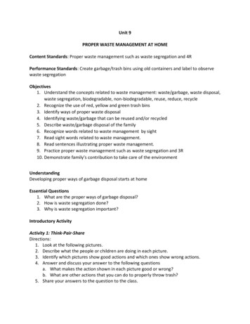
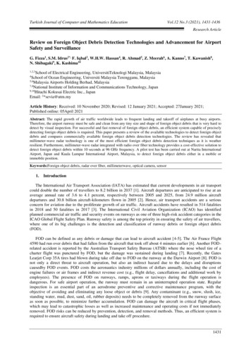
Project Name: Sunchief Mill SiteTask: Engineering Evaluation & Cost AnalysisProblem Statement: Demolition Debris &Waste Source Volume CalculationsSECTION 6.0Prepared by: Brendon Loucks, E.I.T.Date: February 22, 2012Checked By: Rob Ederer, P.E.Date: February 23, 2012MACHINE SHOP FOUNDATIONObjective: Calculate the estimated volume of C&D debris material that will result from the demolition of the Machine Shopfoundation. The foundation is assumed to be a spread footing type running the length of the machine shop’s east andwest walls. Dimensions are as assumed in the drawing below.Solution:Using the surface area method volume method, calculate the estimated volume of material in the foundation.TopBottomVolume Surface Area x Length x (2 ea.)Volume 4.33 ft2 x 125 ft x 2Volume 1083.3 ft3/27Volume 40.1 CY 45 CYSurface Area Atop AbottomSurface Area 192 in2 432 in2Surface Area 624 in2/144 in2/ft2Surface Area 4.33 ft2Atop Length x WidthAtop 24in x 8inAtop 192 in2Abottom Length x WidthAbottom 36in x 12inAbottom 432 in2Page 3 of 15
Project Name: Sunchief Mill SiteTask: Engineering Evaluation & Cost AnalysisProblem Statement: Demolition Debris &Waste Source Volume CalculationsSECTION 7.0Prepared by: Brendon Loucks, E.I.T.Date: February 22, 2012Checked By: Rob Ederer, P.E.Date: February 23, 2012OFFICEObjective: Calculate the estimated volume of C&D debris material that will result from the demolition of the Office building. Thestructure has a total length of 65 ft and width of 25 ft. The Office has estimated height of 10 ft.Solution:Using the FEMA debris estimating empirical equation for General Buildings, calculate the estimated C&D debris for thestructure. For volume estimating purposes, assume a uniform height across the length and width of the structure.Dimensions:Length 65 ftWidth 25 ftHeight 10 ftPage 4 of 15
Project Name: Sunchief Mill SiteTask: Engineering Evaluation & Cost AnalysisProblem Statement: Demolition Debris &Waste Source Volume CalculationsSECTION 8.0Prepared by: Brendon Loucks, E.I.T.Date: February 22, 2012Checked By: Rob Ederer, P.E.Date: February 23, 2012TRAILERObjective: Calculate the estimated volume of C&D debris material that will result from the demolition of the Office building. Thestructure has a total length of 65 ft and width of 25 ft. The Office has estimated height of 10 ft.Solution:Using the CEMA debris estimating empirical equation for a Mobile Home, calculate the estimated C&D debris for thestructure. For volume estimating purposes, assume a uniform height across the length and width of the structure.Dimensions:Length 50 ftWidth 20 ftHeight 8 ftPage 5 of 15
Project Name: Sunchief Mill SiteTask: Engineering Evaluation & Cost AnalysisProblem Statement: Demolition Debris &Waste Source Volume CalculationsSECTION 9.0Prepared by: Brendon Loucks, E.I.T.Date: February 22, 2012Checked By: Rob Ederer, P.E.Date: February 23, 2012BUNKER COMPLEXObjective: Calculate the estimated volume of C&D debris material that will result from the demolition of the Bunker Complex. Thestructure and concrete slabs have the dimensions shown below and discussed herewith. The bunker building itself has aheight of 12 ft and maintains a 6-in concrete wall and floor thickness throughout. For estimating purposes, assume thebunker building has a door opening 9 ft tall by 8 ft wide. The bunker cells stand 4 ft above grade; assume the bunker cellconcrete walls extend 3 ft bgs. The debris pile is estimated to be 30 CY.Solution:Using geometric equations, calculate the estimated C&D debris for the structure. Split the large slab into 3 parts: left,middle and right. Split the bunker cells into two parts, the back knee wall and bunker cell walls.Bunker BuildingDimensions:Length 20 ftWidth 20 ftHeight 12 ftDoor 9 ft x 8 ftVWALLS [(20 ft x 12 ft) x 4 ea. – (8 ft x 9 ft)]*0.5 ftVWALLS 444 ft3VolumeBUNKER BLDG VWALLS VFLOOR VROOFVolumeBUNKER BLDG 444 ft3 200 ft3 200 ft3VolumeBUNKER BLDG 844 ft3/27VolumeBUNKER BLDG 31.3 CYCYVROOF VFLOORVROOF 200 ft3VFLOOR 20 ft x 20 ft x 0.5 ftVFLOOR 200 ft3(Calculations continued on the next page)Page 6 of 15
Project Name: Sunchief Mill SiteTask: Engineering Evaluation & Cost AnalysisProblem Statement: Demolition Debris &Waste Source Volume CalculationsPrepared by: Brendon Loucks, E.I.T.Date: February 22, 2012Checked By: Rob Ederer, P.E.Date: February 23, 2012Small SlabLarge SlabDimensions:Length 20 ftWidth 20 ftThickness 6 inDimensions:Length 20 ftWidth 20 ftThickness 6 inVolumeSMALL SLAB L x W x tVolumeSMALL SLAB 20 ft x 20 ft x 0.5 ftVolumeSMALL SLAB 200 ft3/27VolumeSMALL SLAB 7.4 CYCYVolumeLARGE SLAB VLEFT SLAB VMIDDLE SLAB VRIGHT SLABVolumeLARGE SLAB ([20 ft x 34 ft] [10 ft x 20 ft] [30 ft x 15 ft]) x 0.5 ftVolumeLARGE SLAB 665 ft3/27VolumeLARGE SLAB 24.6 CYCYBunker CellsDimensions:Knee Wall:Length 34 ftWidth 1 ftHeight 7 ftCell Walls:Length 3 ftWidth 2 ftHeight 7 ftVolumeCELLS VKNEE WALL VCELL WALLSVolumeCELLS (34 ft x 1 ft x 7 ft) (3 ft x 2 ft x 7 ft) x 5 eaVolumeCELLS 448 ft3/27VolumeCELLS 16.6 CYCYVolumeBUNKER COMPLEX VolumeBUNKER BLDG VolumeSMALL SLAB VolumeLARGE SLAB VolumeCELLS VDEBRIS*VolumeBUNKER COMPLEX 35 CY 8 CY 28 CY 19 CY 30 CY*VolumeBUNKER COMPLEX 120 CY*Reference Objective statement and Plan View for volume estimate30 CYPage 7 of 15
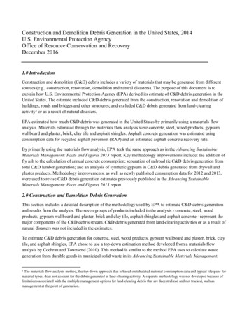
Project Name: Sunchief Mill SiteTask: Engineering Evaluation & Cost AnalysisProblem Statement: Demolition Debris &Waste Source Volume CalculationsPrepared by: Brendon Loucks, E.I.T.Date: February 22, 2012Checked By: Rob Ederer, P.E.Date: February 23, 2012SECTION 10.0 MILL BUILDING COMPLEXObjective: Calculate the estimated volume of C&D debris material that will result from the demolition of the Mill Buildingcomplex. The structures and concrete slabs have the dimensions shown below and discussed herewith.Solution:Using the FEMA debris estimating empirical equations for General Buildings and geometric equations, calculate theestimated C&D debris for the structure. Do to the dilapidated and ‘open air’ condition of the structure, apply a 0.10multiplier to the FEMA debris estimating formula as opposed to the 0.33 multiplier used for more standard, robuststructures. To estimate the volume of the spread footing foundation, use the surface area method.For volume estimating purposes, assume that the slab is 12 in thick. There are 15 visible courses of 8-in tall concretemasonry units (CMU) serving as the Upper Level foundation; for volume estimating purposes assume the CMU foundationwall extends an additional 5 CMU courses bgs onto a spread footing. The assumed spread footing is assumed to have thedimensions shown below. Assume a 100 CY contingency for unknown subgrade conditions and miscellaneous foundations(i.e., ball mill footers, conveyor trench, loading ramp, stairs and landings, etc). Assume 125 CY of miscellaneous debris(i.e., metal, trash, etc.) are present.(Mill Building Complex figures continued on the next page)Page 8 of 15
Project Name: Sunchief Mill SiteTask: Engineering Evaluation & Cost AnalysisProblem Statement: Demolition Debris &Waste Source Volume CalculationsTopBottom(calculations begin on the next page)Page 9 of 15Prepared by: Brendon Loucks, E.I.T.Date: February 22, 2012Checked By: Rob Ederer, P.E.Date: February 23, 2012
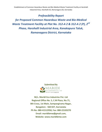
Project Name: Sunchief Mill SiteTask: Engineering Evaluation & Cost AnalysisProblem Statement: Demolition Debris &Waste Source Volume CalculationsPrepared by: Brendon Loucks, E.I.T.Date: February 22, 2012Checked By: Rob Ederer, P.E.Date: February 23, 2012Upper LevelDimensions:Length 30 ftWidth 30 ftHeight 30 ftLower LevelDimensions:Length 125 ftWidth 30 ftHeight 40 ftCMU Foundation WallDimensions:Length 30 ftWidth 0.667 ft (8 in)Height 15 ea x (8 in/12 in/ft) 5 ea x (8 in/12 in/ft) 13.33 ftVolume L x W x HVolume 30 ft x 0.667 ft x 13.33 ft x 2 eaVolume 533.46 ft3/27Volume 19.8 CYCYCMU Wall Spread Footing FoundationDimensions:*As shown in figure.Volume Surface Area x Length x 2 eaVolume 4.33 ft2 x 30 ft x 2 eaVolume 259.8 ft3/27Volume 9.6 CYCYSurface Area Atop AbottomSurface Area 192 in2 432 in2Surface Area 624 in2/144 in2/ft2Surface Area 4.33 ft2Abottom Length x WidthAbottom 36 in x 12 inAbottom 432 in2Large SlabDimensions:Length 125 ftWidth 125 ftHeight 12 in 1 ftAtop Length x WidthAtop 24 in x 8 inAtop 192 in2Volume L x W x HVolume 125 ft x 125 ft x 1 ftVolume 15625 ft3/27Volume 578.7 CYCYVolumeMILL BLDG COMPLEX VUPPER LEVEL VLOWER LEVEL VCMU WALL VCMU FOOTING VSLAB VCONC CONTINGENCY VDEBRISVolumeMILL BLDG COMPLEX 110 CY 575 CY 22 CY 11 CY 625 CY 100 CY 125 CYVolumeMILL BLDG COMPLEXCYPage 10 of 15
Project Name: Sunchief Mill SiteTask: Engineering Evaluation & Cost AnalysisProblem Statement: Demolition Debris &Waste Source Volume CalculationsPrepared by: Brendon Loucks, E.I.T.Date: February 22, 2012Checked By: Rob Ederer, P.E.Date: February 23, 2012SECTION 11.0 WASTE SOURCE, ASBESTOSObjective: Calculate the estimated volume of waste material with asbestos detections at the Sunchief Mill Site. For volumeestimating purposes, assume the piles lie in approximate geometric shapes as observed and noted during the fieldinvestigation or as observed in available photographs.Solution:Use approximate geometric shapes and estimated dimensions observed during the field investigation to calculateestimated volumes of material. Shapes, dimensions, and associated notes gathered from the field log book/documents arepresented in Table 1. For unnamed piles, utilize available figures and photographs to scale approximate dimensions. PileIDs correlate to waste pile source identifications presented on Figure 8, in the EE/CA report.Table 1 – Summary of Waste Source Piles, Asbestos DetectionsPile (ft2)Volume(cf)Volume(cy)Volume,roundedup 1814689263479761044Surface Area (SA) Formulas Used:l Lengthw Widthh Heightd diameterVolume Formulas Used:Page 11 of 15NotesOnly southernportion of pile hadasbestos detection.Assumed as 20% oftotal volume of PileG.Dimensions andshape wereestimated fromFigure 8 and photos.Dimensions andshape wereestimated fromFigure 8 and photos.Dimensions andshape wereestimated fromFigure 8 and photos.
Project Name: Sunchief Mill SiteTask: Engineering Evaluation & Cost AnalysisProblem Statement: Demolition Debris &Waste Source Volume CalculationsPrepared by: Brendon Loucks, E.I.T.Date: February 22, 2012Checked By: Rob Ederer, P.E.Date: February 23, 2012SECTION 12.0 WASTE SOURCE, METALSObjective: Calculate the estimated volume of waste material with metals detections above nrSRLs at the Sunchief Mill Site. Forvolume estimating purposes, assume the piles lie in approximate geometric shapes as observed and noted during the fieldinvestigation or as observed in available photographs.Solution:Use approximate geometric shapes and estimated dimensions observed during the field investigation to calculateestimated volumes of material. Shapes, dimensions, and associated notes gathered from the field log book/documents arepresented in Table 2. For unnamed piles, utilize available figures and photos to scale approximate dimensions. Pile IDscorrelate to waste pile source identifications presented on Figure 8, in the EE/CA report.Table 2Pile ID(Figure8)GHQUVWXYSummary of Waste Source Piles, Metal Detections Above me(cy)Volume,roundedup LS, All Piles12334357528341830903233Lead TCLP rface Area (SA) Formulas Used:l Lengthw Widthh Heightd diameterVolume Formulas Used:Page 12 of 15NotesOnly northernportion of pile hadmetals detectionabove nrSRL.Assumed as 80% oftotal volume of PileG.TCLP exceedsRCRA limits forLeadTCLP exceedsRCRA limits forLead
Project Name: Sunchief Mill SiteTask: Engineering Evaluation & Cost AnalysisProblem Statement: Demolition Debris &Waste Source Volume CalculationsPrepared by: Brendon Loucks, E.I.T.Date: February 22, 2012Checked By: Rob Ederer, P.E.Date: February 23, 2012SECTION 13.0 TOTAL VOLUME OF WASTE MATERIALSObjective: Calculate the total volume of waste materials at the Sunchief Mill Site. Provide a segregation of material type into C&Ddebris versus waste source material.Solution:Sum the totals from the previous calculation to determine the total C&D debris and total waste source material. Sum thetotal C&D debris and total waste source material to determine the total volume waste present at the Sunchief Mill Site.C&D DebrisC&D Quantities:VMACHINE SHOP 1650 CYVMACHINE SHOP FOUNDATION 45 CYVOFFICE 225 CYVTRAILER 325 CYVBUNKER COMPLEX 120 CYVMILL BLDG COMPLEX 1568 CYVTOTAL, C&D DEBRIS VMACHINE SHOP VMACHINE SHOP FOUNDATION VOFFICE VTRAILER VBUNKER COMPLEX VMILL BLDG COMPLEXVTOTAL, C&D DEBRIS 1650 CY 45 CY 225 CY 325 CY 120 CY 1568 CYVTOTAL, C&D DEBRIS 3933 CYVTOTAL, C&D DEBRIS (tons) 3933 CY/(2CY/tn)1967 tonsWaste Source MaterialWaste Source Quantities:VWASTE SOURCE, ASBESTOS 1044 CYVWASTE SOURCE, METALS 3233 CYVTOTAL, WASTE SOURCE VWASTE SOURCE, ASBESTOS VWASTE SOURCE, METALSVTOTAL, WASTE SOURCE 1044 CY 3233 CYVTOTAL, WASTE SOURCE 4277 CYVTOTAL, WASTE SOURCE (tons) 4277 CY x (1.76 tons/1 CY)7528 tonsTotal Waste MaterialVTOTAL VTOTAL, C&D DEBRIS VTOTAL, WASTE SOURCEVTOTAL 3933 CY 4277 CYVTOTAL 8210 CYorVTOTAL 1967 tons 7528 tonsVTOTAL 9495 tonsPage 13 of 15
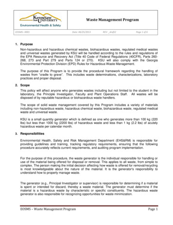
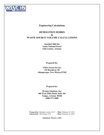
Project Name: Sunchief Mill SiteTask: Engineering Evaluation & Cost AnalysisProblem Statement: Demolition Debris &Waste Source Volume CalculationsPrepared by: Brendon Loucks, E.I.T.Date: February 22, 2012Checked By: Rob Ederer, P.E.Date: February 23, 2012SECTION 14.0 ON-SITE REPOSITORY VOLUME ESTIMATESObjective: Estimate the following quantities for the proposed on-site repository at the Sunchief Mill Site. The existing tailings pondin Area 5 is proposed as the on-site repository location.1. Available volumetric capacity for use as a repository.2. Thickness of the waste material proposed for consolidation within the repository.3. Volume of material needed for use as general fill (minimum of 2 feet general fill required).4. Volume of berm material available for ‘knock down’ use as general fill.5. Conclude if the available berm material is sufficient for use as general fill.Solution:Using measurements collected during the field investigation and available maps, figures, and survey data calculate therequired quantities. For estimation purposes assume the interior side walls of the pond are vertical (no slope). Use thefollowing values for calculations (data sources where values were gather are listed in parenthesis to each value):Interiorl Lengthw Widthh HeightBottom of Repository:l 215 ft (field logbook)w 285 ft (field logbook)h 15 ft (field logbook)SATOP OF BERM 21185 ft2 (figures)Pond Berm Profile(not to scale)1. Available volumetric capacity for use as a repository.Solution: Determine the surface area of the bottom of the repository. Extrude the surface area by the height of the repository tocalculate volumetric capacity.SAREPOSITORY l x wSAREPOSITORY 215 ft x 285 ftSAREPOSITORY 61275 ft2VREPOSITORY SAREPOSITORY x hVREPOSITORY 61275 ft2 x 15 ftVREPOSITORY 919125 ft3/27VREPOSITORY 34042 CY2. Thickness of the waste material proposed for consolidation within the repository.Solution: Using the assumption that the interior side walls are vertical, determine the cubic yard per foot incremental capacity(IC) of the repository. Divide the total volume of waste to be consolidated into the repository (VTOTAL 7804 CY) bythe incremental capacity to determine the height/thickness (tWASTE) of the waste material.ICREPOSITORY VREPOSITORY /hICREPOSITORY 34042 CY / 15 ftICREPOSITORY 2269 CY/fttWASTE VTOTAL / ICREPOSITORYtWASTE 8210 CY / 2269 CY/fttWASTE 3.62 ft3. Volume of material needed for use as general fill (minimum of 2 feet general fill required).Page 14 of 15
Project Name: Sunchief Mill SiteTask: Engineering Evaluation & Cost AnalysisProblem Statement: Demolition Debris &Waste Source Volume CalculationsPrepared by: Brendon Loucks, E.I.T.Date: February 22, 2012Checked By: Rob Ederer, P.E.Date: February 23, 2012Solution: Extrude the surface area of the repository by the depth of general fill materials needed to determine the volume ofmaterial needed for use as general fill. Include a swell factor of 20% and assume recompaction of 95%.VGENERAL FILL SAREPOSITORY x 2 ftVGENERAL FILL 61275 ft2 x 2 ftVGENERAL FILL 122550 ft3/27VGENERAL FILL 4538 CY x (1 20% for swell) x 95% compactionVGENERAL FILL 5173 CY4. Volume of berm material available for ‘knock down’ use as general fill.Solution: Determine the effective thickness (tEFFECTIVE) of berm material that can be utilized as general fill by subtracting thewaste material thickness and general fill thickness from the berm height. The cover soil material thickness (6 inchesof topsoil) will not affect the effective thickness because the disturbed top of berm area will also receive a topsoilcover. Extrude the top of berm surface area by tEFFECTIVE to determine the volume of berm material that can be used asgeneral fill. For estimation purposes use a waste material thickness of 4 ft.tEFFECTIVE h – tWASTE – tCOVERtEFFECTIVE 15 ft – 4 ft – 2 fttEFFECTIVE 9 ftVAVAILABLE BERM MATERIAL SATOP OF BERM x tEFFECTIVEVAVAILABLE BERM MATERIAL 21185 ft2 x 9 ftVAVAILABLE BERM MATERIAL 190665 ft3/27VAVAILABLE BERM MATERIAL 7062 CY5. Conclude if the available berm material is sufficient for use as general fill.Solution: Compare the volume of general fill needed to the volume of berm material available.VGENERAL FILL 5173 CY VAVAILABLE BERM MATERIAL 7062 CYTherefore there is sufficient quantity available within the existingberm for use as ‘knock down’ general fill material.Page 15 of 15
Task: Engineering Evaluation & Cost Analysis Date: February 22, 2012 Problem Statement: Demolition Debris &Waste Source Volume Calculations Checked By: Rob Ederer, P.E. Date: February 23, 2012 . VolumeLARGE SLAB VLEFT SLAB VMIDDLE SLAB VRIGHT SLAB VolumeLARGE SLAB ([20 ft x 34 ft] [10 ft x 20 ft] [30 ft x 15 ft]) x 0.5 ft VolumeLARGE .