Transcription
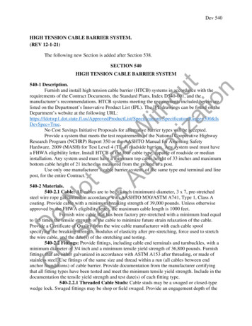
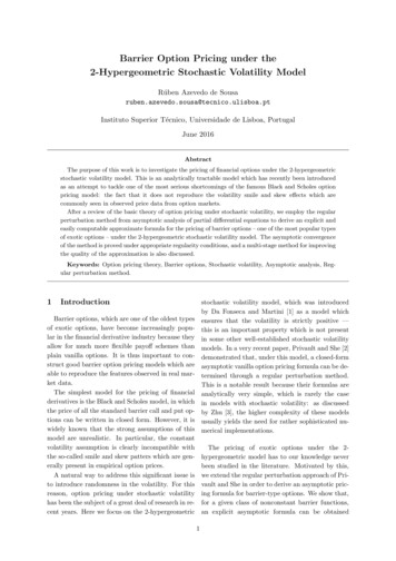
8601 North Black Canyon Highway Suite 103 Phoenix, AZ 85021Issue 14 December 2004For Professionals Engaged in Post-Tensioning DesignDESIGN OF PRESTRESSED BARRIER CABLE SYSTEMSby James D. Rogers11.0 INTRODUCTIONThe selection and design of a vehicle barrier system is animportant element in the structural design of everyparking garage. Some type of barrier system must beerected at the perimeter of the structure and at the openedges of the ramps to prevent automobiles andpedestrians from falling from the open sides.2The International Building Code-2003 gives requirementsfor vehicle impact resistance and states that the barriersystem must have anchorage or attachments capable oftransmitting the resulting loads to the structure. Since thevehicle impact loads are transmitted to the structure, it isimportant that the structural designer consider the vehiclebarrier system in the overall design of the structure.One option for vehicle barrier systems is the use ofprestressed seven wire steel strand conforming to thePost-Tensioning Institute’s Specification for Seven Wire3Steel Strand Barrier Cable Applications . Steel strandsconforming to this specification are capable of restrainingthe impact load of a moving vehicle and are economicaland flexible in meeting the geometric layout of a specificproject. Figure 1.1 shows a cost comparison betweenvarious types of vehicle barrier systems and illustrates whyseven wire steel strand barrier cable systems are a popularchoice for garages of all types of construction.The chart uses the following configurations: Barrier cable system consists of 11 cables Masonry and cast-in-place spandrels are 42 in. highand built on the slab Precast spandrels are 60 in. high and extend over theedge of the slab2.0 BUILDING CODE REQUIREMENTSIBC outlines requirements for parking garagebarrier systems in Section 406.2. This section listsrequirements for both pedestrian protection(Section 406.2.3) and for automobile restraint(Section 406.2.4). While the structural designer willtypically only be concerned with the barriers thatwill handle automobile restraint, these vehiclebarriers will most likely need to meet the provisionsfor pedestrian protection as well. Provisions formeeting both requirements are discussed below.Figure 1.1 – Cost of Exterior Barrier SystemsNote that local building code requirements may bemore stringent than the IBC requirements,particularly with regards to vehicle impact loads,therefore larger values may need to be used in thedesign equations that follow.2.1 Pedestrian protectionBarrier systems for pedestrian protection are required atexterior and interior vertical openings where vehicles areparked or moved, and along open sided walking areas orramps, when the vertical distance to the ground or surfacebelow exceeds 30 in. [762 mm]. Because of thisrequirement, most vehicle barrier systems will double asthe means for providing protection for pedestrians bymeeting the physical requirements of IBC Section1003.2.12.This section states that the guard must form a protectivebarrier not less than 42 in. [1067 mm] high, “measuredvertically from the leading edge of the tread or adjacentwalking surface.” Openings in the guard must be limitedsuch that a 4 in. [102 mm] diameter sphere cannot passthrough any opening up to a height of 34 in. [864 mm].Above a height of 34 in. [864 mm] a sphere of 8 in. [203mm] cannot pass through the opening(s).This section also outlines the minimum loadingrequirements for guards for pedestrian protection,however these loads are not discussed herein since theyrepresent only a small fraction of the load capacityrequired for vehicle barriers.
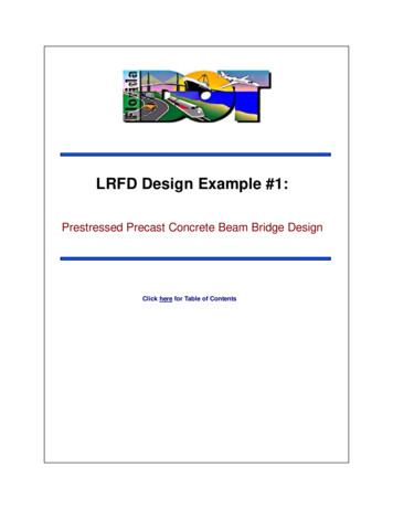
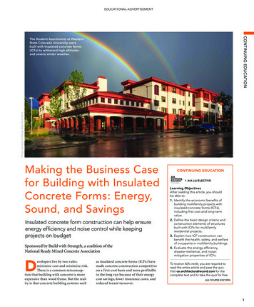
2.2 Automobile restraintIBC Section 406.2.4 requires vehicle barriers not less than24 in. [607 mm] in height, to be placed at the ends ofdrive lanes and at the end of parking spaces where thedifference in adjacent floor elevation is greater than 12 in.[305 mm].Vehicle barriers of all types must meet the physicalrequirements of IBC Section 1607.7, which states thatbarriers for garages designed for passenger cars are to bedesigned to resist a single load of 6,000 lbs [26.70 kN]applied horizontally in any direction to the system. Fordesign purposes, the code assumes the load to act at aminimum height of 18 in. [457 mm] above the floor2surface on an area not to exceed 1 sq ft [0.9 m ].Barriers for garages that accommodate trucks and busesare to be designed in accordance with an approvedmethod that contains provisions for larger vehicles.Depending on the interpretation of the building official,this may include levels or areas of the garage subject totruck traffic such as delivery areas and loading zones. Thetraffic patterns in these areas should be carefully considered,as it can be common for these larger delivery trucks toimpact barriers when backing up in close quarters.Another very important (and often overlooked) elementof the code is the requirement that the barriersystem have anchorages or attachments capable oftransmitting the loads (resulting from a vehicleimpact) to the structure. Prestressed barrier cablesystems are typically anchored to supporting columnsor walls in the garage. It is important that the designercalculate the stresses that will result from a vehicle impactto ensure that these connecting elements have the capacityto resist this force. This is particularly important when theconnecting column is a short “stub” column (sometimesused on the top level of a parking garage) that most likelywill not have the capacity to handle these loads unlessadditional reinforcing is added.The following section will present a design method andexamples that illustrate a procedure for calculating theforces and deflections that result from a vehicle impact.3.0 DESIGN CONSIDERATIONS Failure of the cable or group of cables to resist theimpact without breaking. Failure of the connecting column(s) or wall(s)3.1 Failure of the anchorage systemThe connection of the anchoring system to the column(s)or wall(s) is explained in Section 3 of PTI’s Specification3for Seven Wire Steel Strand Barrier Cable Applications .Appropriate material reports and test data should be usedto calculate the ultimate pull out and shear strength of allcomponent parts being used.Failure caused by the cable pulling out of the anchoringdevice can be avoided by following the material3requirements listed in Section 3 , and by strictenforcement of the installation requirements detailed in3Section 5 ; specifically, all wedge type anchorage devices(the most commonly used in this type of system) must beback-stressed to a force equal to 80% of the MinimumUltimate Tensile Strength (MUTS) of the cable. Barriercable systems are typically tensioned to a relatively lowforce that is not adequate to properly seat the wedges andform the mechanical connection that the system relies on.Back-stressing ensures that the wedges are seated and theproper (permanent) connection is made.Procedures for backstressing are outlined in Section 5 of3the Specification , and calculations for accommodatingthe loss of force due to seating loss are discussed later inSection 5.0 herein.3.2 Limiting deflectionPrestressing steel strand elongates under a load as follows: Where:PLAE(1)P the applied load in lbsL the length of the strand in inchesA area of prestressing steel in sq in.E modulus of elasticity of the steelThe primary design consideration is to provide protectionby resisting the impact of a vehicle without a failure of thebarrier cable system. It is important to recognize thatfailure of the barrier cable system can occur in severaldifferent modes: Failure of the anchorage system (either due to theanchorage (or anchorage assembly) itself pulling outof the column, or due to the cable pulling out of theanchorage). Failure of the system to limit deflection of the cable onimpact to a value that still provides protection.Figure 3.2.1 – Deflection Under a Point Load2POST-TENSIONING INSTITUTE
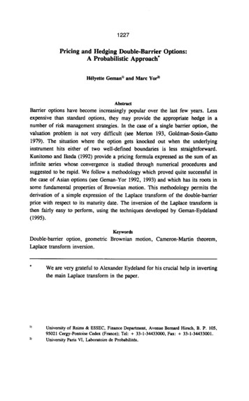
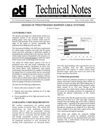
Using the model shown in Figure 3.2.1 and ignoring anyapplied prestressing force, other than what is necessary toremove the slack in the cable, total deflection in a barriercable strand a can be calculated as Pl 2 L a 8 AE 13(2)Using galvanized PC strand with the following properties: Cross Sectional Area of Steel (A) 0.153 in Modulus of Elasticity (E) 28,500,000 lbs/in22and a barrier cable system with a total length (L) of 200 ftand a column to column span (l) of 20 ft, the deflection ofone cable under a 2000 lb load (P) would be: 2000 202 200 a 8 0.153 28,500, 000 133.3 Calculating the capacity of the barriercable systemThe load on a cable during a vehicle impact is notconstant in value, but actually changes with deflection.Therefore the method originally presented in Concrete5International termed the “energy method” is the morerational approach to barrier cable design. This method isbased on energy principles where the kinetic energy of amoving vehicle is converted to cable force and deflection.Using this method, the designer can accurately calculateboth the tension in a cable and the deflection in a cableresulting from the impact of a vehicle of a given masstraveling at a given velocity.The method consists of two steps; first, determining thetension (T) in a cable upon impact, and then determinethe resulting deflection (a). Figure 3.3.1 illustrates a cableof total length L strung between two points A and B. Thecable is assumed to be supported by frictionless bearingpoints at C and D. 1.66 ft.Typically, maximum allowable deflection should belimited to 18 in. in order to prevent the front wheels of animpacting vehicle from traveling over the edge of the slab.However, there are instances where it is important to limitdeflection to a lower value. This includes instances whenthe barrier cable system is placed in front of architecturalmasonry walls or precast panels that are not specificallydesigned to handle impact loads. In this case it would beimportant to limit deflection so that an impacting vehiclewould be stopped before it impacted the wall (and sentdebris to the ground below). It may also be necessary tolimit deflection to the point where a vehicle will notimpact cars in opposing stalls or the edge of the slab atadjacent ramps.When calculated deflection exceeds allowable deflection,the designer has two options:Increase the pretensioning force in the barrier cablestrands (explained in the next section)orAdd intermediate anchorage devices which shorten theeffective length LUsing the previous example and adding intermediateanchorage devices on either side of column line 6 willshorten the effective total length (L) to 100 ft, whichreduces deflection (a) to 1.32 ft.The need for intermediate anchorage devices should bedetermined by the structural designer and their locationsshould be clearly shown in the contract documents.Figure 3.3.1 – Deflection Under Vehicle ImpactThis figure represents a typical straight run of barriercable, anchored only at its end points (A and B). The runmay have several spans in its length but the designershould use the longest span l to calculate tension in thecable as follows:2 EA MV 2T Fe L N (3)Where N is the number of cables resisting the impact, V isthe velocity of the vehicle in ft/sec, and M is the mass ofthe vehicle calculated as:VehicleWeightg(4)POST-TENSIONING INSTITUTE3M
The designer starts by choosing an initial value ofprestressing force Fe in order to calculate T. The resultingvalue is then used in the following equation to calculatethe deflection of the cable (a) upon impact. T Fe T Fe a L l b L (5) 2 AE 2 AE If calculated deflection exceeds allowable deflection, thedesigner can choose a higher value for Fe and recalculatethe resulting force T and deflection a, or intermediateanchors can be added (as described in Section 3.2) andthen recalculate T and a using the smaller value of L.As a check against the IBC requirements, the followingequation can be used to ensure the system meets the 6000lb point load requirement.T ( 6000 / N ) l4a(6)Note that a static load of 6,000 lbs is roughly equivalent toa 5,000 lb vehicle impacting the cables at a velocity of 5mph (14.67 ft/sec).In either equation, the resulting value of T is the totaltension present in each resisting cable upon vehicleimpact. This value should be compared with the yieldstrength of the cables (not the breaking strength) todetermine the factor of safety against yielding. Ifprestressing steel strand conforming to ASTM A416 isused, yield is calculated as 90% of Minimum UltimateTensile Strength.3.4 Column designThe connecting column or wall must be designed to resistthe total lateral load that is transmitted to them. This loadincludes both the initial prestressing force that is presentin each cable, plus the added force generated by a vehicleimpact. This is calculated by using the highest valueobtained for T (from Equation 3 or Equation 6) andmultiplying it by the number of cables used to resist theimpact N, then adding the product of the remainingcables multiplied by the prestressing force (Fe) that hasbeen applied.Each of the connecting columns should be evaluated toensure they are able to withstand this total lateral force.This is usually not a controlling factor on a typical columnthat spans from floor to floor. However, examples in thenext section will show that total prestressing force plus theforce generated upon impact can be well over 40,000 lbswhich can be a factor when using short “stub” columnson the top level of a garage.Since these short columns do not connect above, they donot have the same capacity as the other “typical” columns.This condition should be carefully evaluated to determine4POST-TENSIONING INSTITUTEthe need for additional reinforcing at the anchoringcolumn(s).Another factor to consider when using these stubcolumns is the ability of the intermediate stub columns toresist the same lateral impact load as the rest of the barriersystem. In other words, the columns themselves must beable to resist the lateral forces of a vehicle impact withoutfailure. Failure of intermediate stub column(s) uponimpact would greatly increase the effective length of l,thereby increasing the deflection (a) to the point of notproviding adequate protection. It is particularly importantto evaluate this condition when using small steel columnsthat are simply anchored to the floor.4.0 PRESTRESSING TO ELIMINATECABLE SAGA minimum amount of prestressing force must beapplied to the cables to eliminate sagging of the cablesunder their own weight. PTI’s Specification for Seven Wire3Steel Strand Barrier Cable Applications in Section 5.4requires all cables to be stressed to a minimum force (Fe)of 2 kips [8.9 kN] for 18 ft [5.5 m] spans in order to limitsagging to an acceptable value.Excessive sag in the cables is not visually appealing and itmay allow the passage of a 4 in. diameter sphere eventhough cable spacing is less than 4 in. For example, ifcable spacing is 3.5 in. but there is 1 in. of sag in the cables,a 4 in. diameter sphere will pass through the opening ifenough force is applied to overcome the weight of thecable. Conversely, if cable spacing is 3.5 in. and sag isreduced to 1/8 in., a 4 in. diameter sphere will not passthrough unless enough force is applied to start elongatingthe steel itself.Cable sag is a function of the weight of the cable itself and6the spacing of its supports (l). The following equation isused to calculate sag in barrier cable due to self-weight(w).sinches l 2w8 Fe(7)Using the weight of galvanized PC strand, and based onthe recommendation of using a prestressing force of 2000lbs for an 18 ft span, allowable sag calculates toapproximately 1/8 in. It is recommended that this ratio(1/8 in. per 18 ft or 0.007 in./ft) be used in calculating themaximum allowable sag in spans longer than 18 ft.Using this ratio and solving for Fe, the equation forcalculating the minimum prestressing force required toreduce sag to an acceptable level is: l 2w Fe /8 s /12 (8)
Replacing (s) with the ratio of 0.007l, the equationbecomes: l 2wFe / 8 (.007 l ) /12 (9)The chart included as Appendix A of the Specification forSeven Wire Steel Strand Barrier Cable Applications listsapproximate values for the weight of various types ofstrand used as barrier cables. Use these values in the aboveequation to ensure that the prestressing force being usedwill eliminate sag to an acceptable value. If the forceobtained in Equation 9 is higher than the value used inthe design equations the designer has two options: Use the higher prestressing force obtained in Equation9 and re-run the design equations, finding a new valuefor T, a, and for the total load being applied to theanchoring columns. Add some type of intermediate spacers or supports toreduce the value of l in Equation 9.Adding intermediate spacers or supports increasesmaterial and labor costs, but may be necessary in garageswith very long spans or where it is not desirable toincrease the loading on the anchoring columns (orbrackets). Note that since these spacers do not provideany lateral resistance they only reduce the value of l asused in Equation 9.The actual technique used for backstressing will dependon the particular job site conditions and is explained inmore detail in Section 5.4 of the Specification for SevenWire Steel Strand Barrier Cable Applications.It is appropriate to assume that the anchorage willexperience the full seating loss only upon backstressing.This value is typically 3/8 in. but can vary depending onthe particular anchorage system being supplied. Thefollowing equation can be used to calculate the jackingforce (Fpj) that will be required to maintain the requiredfinal effective force (Fe) that was determined in the designequations.Fpj Fe SeatingLoss A E12 L(10)Since seating loss can vary according to the type ofanchorage system and/or stressing equipment being used,it is typically not appropriate for the designer to specify arequired jacking force, but instead should specify therequired final effective force (Fe) and then require thebarrier cable material supplier to calculate the requiredjacking force according to materials and equipment beingsupplied to the project. The supplier should submit thisjacking force to the designer as part of the submittalpackage. The supplier should also supply a stressingequipment calibration chart with the stressing equipmentthat is being supplied to show the gauge force thatcorresponds to the required jacking force.6.0 DESIGN EXAMPLES5.0 CALCULATING JACKING FORCEAs previously stated, the relatively low prestressing force(Fe) that is applied to the cable to reduce deflection andeliminate sag is not enough to properly seat the wedgesinto the anchorage devices typically used with seven wiresteel strand barrier cable systems. These wedge typeanchorage devices are designed to form a mechanical (nota friction) connection between the cable, the wedge, andthe anchor, when the wedges are fully seated. It takes anapplied force equivalent to 80% of the MinimumUltimate Tensile Strength (MUTS) of the cable to fullyseat the wedges. When using ½ in. grade 250 PC strand,this force is 30,600 lbs, much higher than the prestressingforce (Fe) that is being applied to the cables.In order to apply the required seating force, the installermust backstress the cable at all anchors to the required80% of MUTS. This involves stressing each cable to aforce equivalent to the calculated final effective force (Fe)plus an additional force needed to compensate for theseating loss that will occur, then removing the stressingjack and using it on the other side of the anchoringassembly to apply the required 80% of MUTS and fullyseat the wedges.6.1 Meeting pedestrian requirementsAll of the following design examples will use 11 cables,spaced at 4 in. center to center, with the center of the firstcable positioned 3.5 in. above the floor. Using ½ in. cable,this results in a 3.5 in. spacing between each cable, and theheight of the center of the top cable is 43.5 in.Assuming the cables have enough prestressing forceapplied to them to limit sag and deflection, this will meetthe requirements relating to opening sizes and totaloverall height.6.2 Number of cables resisting impactThe International Building Code requirements state thatthe system must resist an impact load located a minimumof 18 in. from the floor and centered on a 1 sq ft area.Given this criteria and the cable spacing cited above, all ofthe following examples assume that a total of three (3)cables will resist the vehicle impact.POST-TENSIONING INSTITUTE5
6.3 Example 1:Total length of cable (L) 180 ftSpan length (l) 18 ftGrade 250 ksiYield strength 90% MUTSCross sectional area (A) 0.153 sq in.Modulus of Elasticity (E) 28,500,000Weight of vehicle 5,000 lbsWidth of vehicle 6 ftImpact velocity 5 mphThe yield strength of the cable is 34,425 lbs, which resultsin a factor of safety against yielding in this example of3.93. Total load transmitted to the end (anchoring)columns would be:Cable(8768 3) ( 3000 8) 50,305 lbsUse Equation 6 to check conformance with building coderequirementsT ( 6000 / 3) 18 7,500 lbs4 1.2The mass of the vehicle is determined by Equation 4:M 5000 156 lb-sec 2 /ft32Since this result is lower than the value obtained for Tusing the energy method, no additional steps are required.To determine the required jacking force, assume thesupplier has given a value of 3/8 in. for expected seatingloss and use Equation 10 as follows:Select an initial pretensioning force (Fe) of 3,000 lbs andcalculate the tension upon impact using Equation 3:Fpj 3000 2 0.153 28,500, 000 156 7.34 2 3, 000 1803 T 8, 768 lbsUsing this pretensioning force, deflection is calculatedusing Equation 5:a ( 8768 3000 ) 180 (18 6 ) ( 8768 3000 ) 180 2 0.153 28, 500, 00 2 0.153 28, 500, 00 1.2 ft6POST-TENSIONING INSTITUTE0.375 0.153 28, 500, 00012 180 3, 757 lbs
6.4 Example 2All of the above data is the same, except span length (l) isincreased to 27 ft and the total length (L) is increased to270 ft. 27 2 0.544 Fe / 8 3,147 lbs (.007 27 ) /12 Using the same initial prestressing force (Fe) of 3,000 lbsand solving for T:Since the force being used (Fe 5,000 lbs) exceeds the forcerequired to reduce sag, no further steps are required.2 0.153 28,500, 000 156 7.34 2T 3, 000 2703 7,366 lbs6.5 Example 3This example will use the same spans given in Example 1,but will increase the vehicle weight to 17,000 lbs (deliveryvehicle on a plaza level):The mass of the vehicle isthisUsinga force,deflectioniscalculatedas ( 7366 3000 ) 270 ( 27 6 ) ( 7366 3000 ) 270 2 0.153 28, 500, 00 2 0.153 28, 500, 00 1.69 ftIn order to limit deflection to 1.5 ft, use a higher initialprestressing force of 5,000 lbs and recalculate the resultingtension (T) and deflection (a):2 0.153 28,500, 000 156 7.34 2 5, 000 2703 T 8,382 lbsand deflection isa ( 8382 5000 ) 270 ( 27 6 ) ( 8382 5000 ) 270 2 0.153 28, 500, 00 2 0.153 28, 500, 00 1.49 ftThis limits deflection to 18 in. but total lateral forcetransmitted to the anchoring columns increases due tothe increase in prestressing force applied to the cables.(8382 3) ( 5000 8) 65,146 lbsSince the span length is exceeds 18 ft use Equation 9 tocalculate the minimum amount of prestressing forcerequired to reduce sag to an acceptable value in the 27 ftspan.M 17000 53132Use an initial prestressing force of 3,000 lbs and solve forT:2 0.153 28,500, 000 531 7.34 2 3, 000 1803 T 15, 486 lbsUsing this value the resulting deflection isa (15486 3000 ) 180 (18 6 ) (15486 3000 ) 180 2 0.153 28, 500, 00 2 0.153 28, 500, 00 1.78 ftIn this example, the prestressing force would have to beincreased to 9,000 lbs in order to limit deflection to 1.5 ft,which would increase the total load transmitted to theanchoring columns to 125,000 lbs. Deflection could alsobe limited to 1.5 ft by adding intermediate anchorages toreduce the total effective length (L) to 90 ft and increasingprestressing force to 4,000 lbs. This would reduce the totalload transmitted to the columns to 98,000 lbs, but the useof the shorter cable length decreases the factor safetyagainst yielding to 1.6.Another option would be to decrease cable spacing in thearea of impact and use five cables pretensioned to 4,000lbs to resist the impact. This would limit deflection to 1.46ft and would increase the factor of safety to 2.8.POST-TENSIONING INSTITUTE7
7.0 LIST OF NOTATIONSA Cross sectional area of cable, in8.0 REFERENCES21. James D. Rogers is Director of CertificationPrograms and Construction Technologies at thePost-Tensioning Institute, Phoenix, AZa Cable deflection, ftb Width of vehicle, ftE Modulus of elasticity of cable, lb/in2. International Code Council, Inc. (2003).International Building Code, Falls Church, VA2Fe Final effective pretensioning force, lbsFpj Jacking force, lbs2g Acceleration due to gravity (32.174 ft/sec )L Total length of cable, anchor to anchor, ftl Span of cable between supports, ft2M Mass of vehicle, lb-sec /ftN Number of cables resisting impactP Applied load, lbss Sag in cable due to self weight, in.T Cable tension on impact, lbV Velocity of vehicle, ft/sec.w Weight of cable per ft, lbs3. Post-Tensioning Institute (1998). Specification forSeven Wire Steel Strand Barrier Cable Applications,Phoenix, AZ, www.post-tensioning.org4. Post-TensioningDesign,Institute(2001).Construction and Maintenance of Cast-In-PlacePost-Tensioned Concrete Parking Structures,Phoenix, AZ, www.post-tensioning.org5. American Concrete Institute (1989). ConcreteInternational-Designing Prestressed Barrier Cables,Pages 67-72 by Hoshang Presswalla, FarmingtonHills, MI, www.aci-int.org6. USGS, Department of the Interior, Stream-GagingCableways, by C. Russell Wagner, Reston, VA,www.usgs.Technical NotesISSUE 14 December 20048601 North Black Canyon Highway, Suite 103Phoenix, Arizona 85021(602) 870-7540 Fax (602) 870-7541www.post-tensioning.orgThis document is intended for the use of professionals competent to evaluate the significance and limitations of its contents and who will acceptresponsibility for the application of the materials it contains. The Post-Tensioning Institute reports the foregoing material as a matter of information andtherefore disclaims any and all responsibility for application of the stated principals or for the accuracy of the sources other than material developed bythe Institute. The Post-Tensioning Institute, and the Author, in publishing these Technical Notes makes no warranty regarding the recommendationscontained herein, including warranties of quality, workmanship or safety, express or implied, further including, but not limited to, implied warranties ormerchantability and fitness for a particular purpose. THE POST-TENSIONING INSTITUTE AND/OR THE AUTHOR SHALL NOT BE LIABLE FOR ANYDAMAGES, INCLUDING CONSEQUENTIAL DAMAGES BEYOND REFUND OF THE PURCHASE PRICE OF THIS ISSUE OF TECHNICAL NOTES.The incorporation by reference or quotation of material in the Technical Notes in any specifications, contract documents, purchase orders, drawings, orjob details shall be done at the risk of those making such reference or quotation and shall not subject the Post-Tensioning Institute and/or the Author toany liability, direct or indirect, and those making such reference or quotation shall waive any claims against the Post-Tensioning Institute and the Author.COPYRIGHT 2004 BY POST-TENSIONING INSTITUTE, ALL RIGHTS RESERVEDPRINTED IN U.S.A8POST-TENSIONING INSTITUTE
Barrier cable system consists of 11 cables Masonry and cast-in-place spandrels are 42 in. high and built on the slab Precast spandrels are 60 in. high and extend over the edge of the slab 2.0 BUILDING CODE REQUIREMENTS IBC outlines requirements for parking garage barrier systems in Section 406.2. This section lists