Transcription
Offshore Wind Energy FacilityCharacteristicsWalt MusialPrincipal EngineerManager of Offshore WindNational Renewable Energy LaboratoryMarch 5, 2018BOEM’s Offshore Wind and Maritime Industry Knowledge Exchange Workshop
NREL - 40 Years of Clean Energy Research World-class facilities, renowned technology experts Nearly 1,700 employees, including more than 400 early-career researchers andvisiting scientists Nearly 750 active partnerships Campus is a living energy laboratory National economic impact of 872M LEENERGYENERGYLABORATORY2
Scope of NREL MissionEnergy FFICIENCYBuildingsENERGYSYSTEMSINTEGRATIONPower terData andVisualizations
Wind Turbine Basic TerminologyRotor is the assembly ofblades and hubNacelle contains the drivetrain and mechanical toelectrical conversionsystemsMinimum Tip Clearance75 ft to 100 ftNATIONAL RENEWABLE ENERGY LABORATORY4
Wind Turbine Size- Offshore Wind Growth Continues15 MW Turbines are on the drawing boardLarger turbines fewer turbines and wider spacingNATIONAL RENEWABLE ENERGY LABORATORY5
Offshore Wind – Current Technology Status 111 projects, over 13,000 MW installed(end of 2016) 99% are on fixed bottom supportstructures in shallow water ( 50 m) Turbine capacity 6-8 MW with upwindrotors – 150 m -180 m diameter 90 meter towers Direct drive generators or single stagegeared drives with medium speedgenerators Capacity factors 40 to 50 percent Capital cost dropping due toexperience, competition, technologyand lower risk perception O&M higher than land-based Leverages and expands existingmature marine industries: Offshore Oil and gas Submarine cableGE-Haliade 6 MW Turbines 30 MW Block Island Wind FarmOffshore Wind Power6National Renewable Energy Laboratory
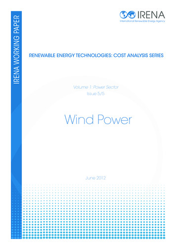
Fixed Bottom Foundation TypesNATIONAL RENEWABLE ENERGY LABORATORY Fixed bottom supportstructures are feasible inwater depths from 0 to 50-m Support structures havebeen adapted from oil andgas industry Monopiles are the mostcommon so far (smallestfootprint).7
Block Island Wind Farm – Rhode IslandNATIONAL RENEWABLE ENERGY LABORATORY Developer: Deepwater Wind 30 MW capacity, 5 turbines GE wind turbines with outputcapacity of 6 megawatts 1st commercial project installed inthe United States (Dec 2016) Fixed bottom jacket supportstructures in about 26-m water depth Upwind rotors – 150 m diameter Produces electricity for 17,000 RIhomes8
Wind and Wave Resource Measurements Fixed MET mastsare expensive andare being replacedby floating LIDARbuoys. Site specificmeasurements areneeded for: ResourcevalidationFixed METMastFLiDAR: Floating LIDAR Power productionAXYS FLiDAR 6-m buoy typically used for wind and waveassessments installed near a fixed meteorological mast.Photo courtesy of AXYS TechnologiesNATIONAL RENEWABLE ENERGY LABORATORY9
Wind Plant Rectangular Array – Horns Rev DenmarkNATIONAL RENEWABLE ENERGY LABORATORY10
Wind Plant Layout Needs to Consider Wake EffectsHorns Rev I Offshore Wind Plant(Source: Vattenfall, Photo by Christian Steiness)
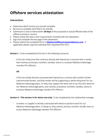
Turbine Spacing is Determined by the Rotor Diameter Eight rotor diameter spacing is shown in figure above. Distance increases as the diameter of rotor diameter increases Generally the number of rotor diameters stays constant as turbines scale up Number of diameters used for spacing depends on available site area, cablelength (cost), water depth and , and atmospheric conditions.NATIONAL RENEWABLE ENERGY LABORATORY12
Wind Plant Layout ConsiderationsWind Rose – Indicates theannual average wind directionNATIONAL RENEWABLE ENERGY LABORATORY13
Wake Losses Depend on Atmospheric Stability Wind turbines wakes have less energyand higher turbulence. Energy is replenished by mixing withadjacent atmospheric layers Atmospheric stability conditionsdominate the rate of mixing andreplenishment In stable atmospheres, vertical layersare stratified and wake turbulencepersists farther downstream In unstable atmospheres, verticalmixing due to thermal convectionhelps replenish energy in the wakesmore quicklySimulator for Wind Farm Applicationsshowing turbine wake effects(Source: NREL)14
Industry Array Spacing: Installed Projects over 200MWCompared to MA WEA Analysis SpacingMean of 18 Wind Plants15
Subdividing the Massachusetts WEA(Source: BOEM 2013) Current WEA area 742,974 acres, or 3,006.7 square kilometers (km2) About 130 lease blocks, 2088 aliquots16
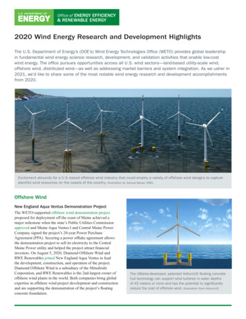
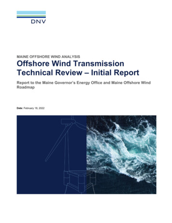
Bathymetry: A Major FactorHalf the area is in water deeper than 50-mTotal 2088 AliquotsMean DepthData Source: NOAA National Geophysical Data l17
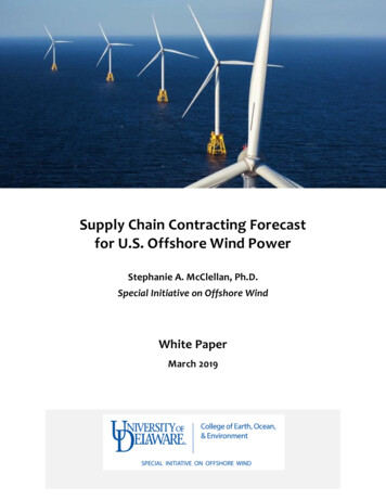
Massachusetts Wind Energy Area - Wind CharacteristicsAverage Wind Speeds Improve from West to EastData from AWS Truepower – 14 years hourly data set, mean annual wind resource grid(WRG/B) data containing wind speed, wind direction, and frequency distribution at 90 m.ABMA WEA showing annual average wind speed between9.2 m/s and 9.4 m/sMA WEA annual average windfrequency rose with prevailingsouthwest18
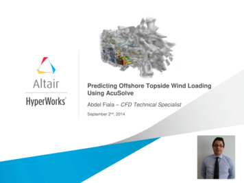
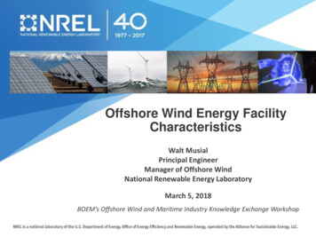
Massachusetts Wind Energy Area - Four Lease AreasArea less than 50mArea(km2)407.45414.92408.31394.58Area km2Lease AreasArea 1Area 2Area 3Area 41200Total Area (km2)1000Total Area ( 50m)80060040020001234Leasing Area12ØrstedBay State VineyardWindWind 3 Unleased4Depth 50 MetersDepth 50 MetersUnleased Lease Area Characteristics4 leasing AreasDiagonal delineationsminimizes upwind conflictsShallower water less than 50mdepth is equal for all areasDeeper water may bedeveloped with differenttechnology (e.g. floating)
Massachusetts and RI/MA Wind Energy AreasFigure Source:BOEM20
Wind Facility Array and Export Cable SystemNATIONAL RENEWABLE ENERGY LABORATORY21
Array and Export Cable Elevation SchematicOffshore Wind Electric Cable Schematic from Turbines to Onshore Grid Connection Cables are typically buried 6 ft below sea bed Scour and subsea geology may expose cables over time Cables that cannot be buries are protected withmattresses, rock placements, armoring techniquesNATIONAL RENEWABLE ENERGY LABORATORYOffshore Wind ElectricService Platform(Substation)Photo Credit: Walt Musial22
Alternative Layouts to Reduce Wake Losses Alternative layouts can increase energyproduction and lower cost High fidelity wind array models are beingdeveloped to optimize energy layoutdesigns Wind system array models can minimize– Minimize excess turbine loads– Maximize power output of existingfacilities through advanced controls– Optimize layout for most efficient useof wind energy area.DKHorns Rev II – LayoutNATIONAL RENEWABLE ENERGY LABORATORY23
Thank you for your attention!Walt MusialOffshore Wind ManagerNational Renewable Energy Laboratorywalter.musial@nrel.govPhoto Credit : Dennis Schroeder-NREL24
NATIONAL RENEWABLE ENERGY LABORATORY 9 Wind and Wave Resource Measurements FLiDAR: Floating LIDAR Fixed MET Mast AXYS FLiDAR 6-m buoy typically used for wind and wave assessments installed near a fixed meteorological mast. Photo courtesy of AXYS Technologies Fixed MET masts are expensive and are being replaced by floating LIDAR buoys.