Transcription
MAINE OFFSHORE WIND ANALYSISOffshore Wind TransmissionTechnical Review – Initial ReportReport to the Maine Governor’s Energy Office and Maine Offshore WindRoadmapDate: February 18, 2022
Table of contents11.1EXECUTIVE SUMMARY. 1Key considerations for Maine and regional transmission planning122.12.22.3INTRODUCTION . 3Objectives3Report structure3GEO’s role333.13.23.3OFFSHORE TRANSMISSION TECHNOLOGY REVIEW . 5Offshore system components6Offshore substation platform (OSP)7Grid connection technology (alternating current versus direct current)1244.14.2OFFSHORE TRANSMISSION PLANNING AND DESIGN. 19Offshore transmission connection concepts19Design considerations for coordinated offshore transmission planning2355.15.2OFFSHORE TRANSMISSION OWNERSHIP AND FINANCING STRUCTURES . 31Ownership and development31Financing and cost recovery3366.16.2ANALYSIS OF RENEWABLE INTERCONNECTION IN MAINE. 34Methodology and assumptions35Simulation results3577.17.2TRANSMISSION BEST PRACTICES TO REDUCE IMPACTS . 37Review of transmission best practices and government policies37Best practices to reduce impacts on the marine environment and ocean users408MAINE AND REGIONAL TRANSMISSION STRATEGIES . 499GLOSSARY OF ACRONYMS AND TERMS USED IN THIS REPORT . 51List of figuresFigure 3-1. Gulf of Maine bathymetry . 5Figure 3-2. Typical components of an offshore wind energy transmission link for deep-water conditions* . 7Figure 3-3. Semi-submersible (on the left) and Barge (on the right) floating OSP concepts . 8Figure 3-4. Design concepts for floating substations . 9Figure 3-5. Deep water fixed foundation types . 10Figure 3-6. Underwater offshore electrical substation concept . 12Figure 3-7. Typical Offshore HVAC radial link . 13Figure 3-8. Typical Offshore HVDC radial link . 13Figure 3-9. Choosing AC versus DC based on transmission distance . 14Figure 3-10. Available ratings of VSC-HVDC-based transmission technologies . 16Figure 3-11. Cable transmission power-distance curves. 18Figure 4-1. Bespoke (radial) transmission schematic* . 20Figure 4-2. Bundled offshore transmission design* . 21Figure 4-3. Offshore grid with offshore platform interlink* . 22DNV – www.dnv.comPage i
Figure 4-4. Typical coordinated transmission planning process . 23Figure 4-5. Illustrative placement of OSP relative to offshore wind lease area* . 25Figure 4-6. Generic illustration of offshore symmetric monopole HVDC link . 28Figure 4-7. Generic illustration of offshore HVAC radial transmission link . 29Figure 6-1. Injection MW limits of 345 KV and 115 kV high voltage substations . 36List of tablesTable 3-1. Overview of deep water fixed foundation . 11Table 3-2. Limiting factors in HVDC link power ratings . 15Table 3-3. Phenomena impacting AC cable power rating . 17Table 4-1. Key considerations for coordinated transmission development . 22Table 4-2. Example screening criteria to determine the optimal offshore transmission solution . 27Table 7-1. Key synthesized literature and data sources. 41DNV – www.dnv.comPage ii
1EXECUTIVE SUMMARYThis executive summary highlights the approach and key results of DNV’s initial offshore wind transmission technical review.Supported by a 2.166 million grant from the US Economic Development Administration, the Governor’s Energy Office(GEO) is developing an Offshore Wind Roadmap (the “Roadmap”) to grow Maine’s overall economy and improve itseconomic resilience through development of an offshore wind industry in Maine. The Roadmap is being developed by anadvisory committee and four working groups with broad public input, focusing on energy markets and strategies, fisheries,environment and wildlife, and supply chain, workforce development, ports, and marine transportation.This offshore wind transmission technical review initial report aims to inform the Roadmap by assessing various options fordevelopment of grid integration, including policy options, such as coordinated onshore and offshore transmissioninfrastructure. This includes an analysis of offshore and onshore transmission technology and design options, identificationof opportunities for cost-effective, strategic approaches (including regional coordination) to develop necessary transmissionassets, and identification of transmission-related best practices to mitigate impacts on people and the environment.This initial technical review was developed through and informs the State’s Roadmap process, as well as supports theMaine Public Utilities Commission’s requirement in section 4 of Public Law 2021 chapter 327 to conduct a study oftransmission infrastructure related to offshore wind generation with stakeholder input and in consultation with the Governor’sEnergy Office and Office of the Public Advocate. This initial technical review is intended to inform current and futurestakeholder work through the Maine Offshore Wind Roadmap.1.1Key considerations for Maine and regional transmission planningThe choice of transmission technology, design, approach to planning, ownership and financing structures, and supportivepolicy all have an impact on the performance, cost, feasibility and environmental impacts of offshore transmission networks.In order to support the State of Maine in taking a well-informed approach to transmission planning, DNV has completed anextensive review of available, state-of-the-art transmission technologies and designs that are applied to both floating andbottom-fixed offshore wind projects and assessed their suitability for application in the future offshore transmission networkserving Maine and the region. 1 The Gulf of Maine’s bathymetry shows significant areas with water depths of 50 to 100meters and vast areas with deeper water; at these depths, floating wind turbines will be necessary for commercial-scalewind project development in the Gulf of Maine. 2While several different approaches can be taken, these transmission considerations represent those most applicable to theState of Maine and the characteristics of the Gulf of Maine. Stakeholder engagement early and often throughout transmission planning and development is critical tosuccess. Effective engagement should include the state, regional, and federal organizations with jurisdictional oversightfor offshore transmission development, along with the development community and all affected and potentially affectedparties, including fishing and ocean user communities as well as the general public. Substation and cable technology choices in the Gulf of Maine are contingent upon regional and site-specificdevelopment needs and technology maturity. The relatively large size (MW capacity) of the offshore wind projectsanticipated in the Gulf of Maine and the potential distance of future lease areas from shore generally favors HVDCtechnology over HVAC, although it is possible to extend AC technology with additional reactive compensation andfiltering measures. Floating offshore substation platforms (OSPs) are a viable choice based on Gulf of Maine1 DNV is not involved in the ongoing offshore wind development projects in the Gulf of Maine. This report is not related to any specific project, but is designed to informfuture offshore wind planning in the Gulf of Maine.2 Please see DNV’s State of the Offshore Wind Industry Report, also developed to inform the State’s Roadmap process, for additional discussion of the offshore windindustry and the various floating turbine technologies available and under development. 0-%20State%20of%20the%20OSW%20Industry Final.pdf.DNV – www.dnv.comPage 1
bathymetry. Rapid innovation is occurring for OSPs as well as components such as dynamic high voltage cablesneeded to withstand fatigue due to ocean movements. Future offshore wind development in the Gulf of Maine would likely employ multiple transmission designs totake advantage of geographical and resiliency benefits of project development. Some projects would likelyconnect directly to onshore points of interconnection (POIs) through bespoke or radial connections, while others wouldlikely develop bundled and/or multi-terminal links to reduce cabling and provide offshore and onshore grid reliabilitybenefits. Comprehensive cost benefit analyses and coordinated planning could enable state and regional entities tohelp determine the best transmission design approach within the context of overall long-term grid development. Coordinated transmission planning is complex, but could provide an opportunity to strategically developoffshore wind in the Gulf of Maine. The primary benefits of coordinated planning would be to ensure that the offshoretransmission grid is flexible and capable of adapting with future needs and minimizing impacts on marine environmentsand ocean users. Coordinated planning is a complicated process that would require states and regional entities to worktogether and with many other stakeholders, including the regulated asset (utility) and developer communities, to bestintegrate offshore wind projects brought online by different entities and at different timelines as the industry matures. Todate, coordinated offshore transmission has not been implemented in the United States, although some jurisdictions areexploring various approaches. Standardization of technologies and interconnection strategies is necessary to promotecompatibility throughout and across multiple leasing and planning timetables. This type of approach would ideallyminimize the amount of cable necessary to connect projects to the grid, thus mitigating impacts on marine environmentsand ocean users. Offshore transmission ownership structures vary, and may have cost and deployment implications. Regulated(such as utility or “Transco” owned) offshore transmission assets may have some advantages over merchant(developer) owned transmission. Regulated transmission structures may carry less risk to project completion, may havegreater opportunities for standardization and coordination with other similar projects developed in the region, may havehigher chances of allocation of costs to the wider region, and may have less cost recovery risk. Merchant ownedtransmission may work well for bespoke connections, and streamlined cost recovery mechanisms may minimizeplanning delays. Competitive, open processes tend to produce favorable financial results. Selection of onshore POIs should consider numerous factors. Key factors that affect onshore POI selection includethe location of the offshore wind areas, grid reliability analyses, nearness of the substation to the shore, costoptimization of onshore and offshore cable lengths, onshore substation expandability, populated urban areas, impactson the marine environment, and impacts on fishing and other near-shore activities. Onshore grid updates may be required to provide grid reliability for the injection of significant new renewableenergy, including offshore wind. Prior state and regional analyses, as well as DNV’s high-level injection analysis inthis report (Section 6), suggest that while there’s some availability, significant offshore wind development willnecessitate some onshore grid upgrades to deliver energy and address grid reliability. There are ongoing studies atISO-NE to examine grid upgrades necessary to support the integration of wind as well as other onshore resourcesthrough 2050.DNV – www.dnv.comPage 2
2INTRODUCTIONThis offshore transmission technical review initial report describes offshore and onshore transmission planning, design,technologies, ownership and financing structures. This review analyzes renewable interconnection in Maine and isconcluded by a set of transmission strategies potentially applicable to the state of Maine, understanding floating offshorewind farms in the Gulf of Maine would be located in deep, federal waters.2.1ObjectivesThe key objectives of this offshore wind transmission technical review initial report are to: Provide an independent review of available and emerging global transmission-related technologies and approaches Provide an understanding of transmission siting and interconnection locations customary for offshore wind projects,based on nearshore high voltage Describe the necessary steps and investment to meet onshore and offshore transmission needs associated withinterconnection points, including methods of encouraging efficient transmission investment Consider the State’s interconnection alternatives and the impact offshore wind may have on Maine’s grid Provide best practices and state, regional, and federal planning around transmission options, including built projects, aswell as those proposed but not yet developed Describe the potential for coordinated or regional offshore transmission infrastructure, and the associated cost andbenefit impacts of those strategies Describe possible public and private transmission financing and ownership structures Recommend strategies to protect and reduce impacts to marine and environment and ocean users Present potential considerations to pursue transmission strategiesThe results and conclusions presented herein are intended to inform the State of Maine’s Offshore Wind Roadmap andsupport a Maine Public Utilities Commission requirement to study offshore wind transmission serving the state. DNV is notinvolved in the ongoing offshore wind development projects in the Gulf of Maine. This report is not related to any specificproject but is designed to inform future offshore wind planning in the Gulf of Maine.2.2Report structureThe remainder of this assessment is structured as follows: Section 3 Offshore transmission technology review Section 4 Offshore transmission planning and design Section 5 Offshore transmission ownership and financing structures Section 6 Analysis of renewable interconnection in Maine Section 7 Transmission best practices to reduce impacts Section 8 Maine and regional transmission strategies2.3GEO’s roleThe GEO is the sponsor of this study and selected DNV to conduct this work. DNV prepared this initial technical review toinform current and future stakeholder work through the Maine Offshore Wind Roadmap, as well as to satisfy the directive ofsection 4 of Public Law 2021 chapter 327. GEO worked with DNV to conduct initial coordination with working groups,participate in meetings between stakeholders and consultant, and prepare this report. Additional stakeholder engagementDNV – www.dnv.comPage 3
will need to be done as the Roadmap process considers this topic. GEO coordinated with the PUC on the development ofthe study.DNV – www.dnv.comPage 4
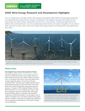
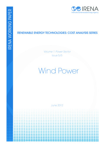
3OFFSHORE TRANSMISSION TECHNOLOGY REVIEWThis offshore transmission technology review describes available and emerging offshore transmission-related technologiesand approaches that may be considered for the Gulf of Maine. This includes a discussion of existing and emerging solutionsfor offshore substations, as well as a review of the two grid connection technologies - high voltage alternating and highvoltage direct current (HVAC and HVDC) – available and under development to deliver power from the substations to thegrid.Floating wind turbines will be necessary for Gulf of Maine wind development. While nearly all existing offshore windfarms consist of bottom-fixed wind turbines, the ocean floor depth threshold for bottom-fixed turbines is typically consideredto be about 60 meters (m). While it is technically possible to build bottom-fixed structures in much deeper water depths, theweight and cost of such structures increases exponentially as water depth increases, making a bottom-fixed wind farmcommercially unfeasible in deep water. The Gulf of Maine has significant areas with water depths of 50 to 100 m and vastareas with deeper water (see Figure 3-1), as well as some of the best wind resources in North America. These conditionssuggest that floating wind turbines will be necessary for commercial-scale offshore wind development in the Gulf of Maine. 3Figure 3-1. Gulf of Maine bathymetrySource: 4C OffshoreGiven this context, this initial report focuses on the transmission equipment likely to be used with floating turbines.3 Please see DNV’s State of the Offshore Wind Industry Report, also developed to inform the State’s Roadmap process, for additional discussion of the offshore windindustry and the various floating turbine technologies available and under development. 0-%20State%20of%20the%20OSW%20Industry Final.pdf.DNV – www.dnv.comPage 5
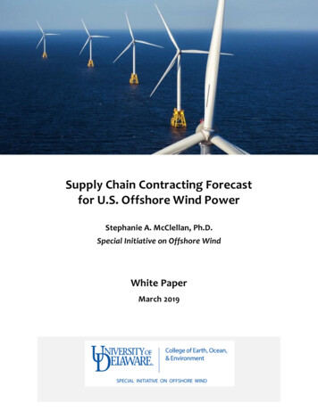
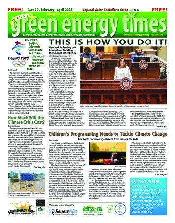
Highlights in this section With water depths typically between 100 m and 200 m, the federal waters of the Gulf of Maine are suitedfor floating turbine foundations. It is anticipated that commercial scale offshore projects will require floatingoffshore substation platforms (OSP) as well. These floating OSP technologies are still in development. In the shallowest parts of the Gulf of Maine, alternatives to floating OSPs could be considered, such as tallbottom-fixed foundations (jacket). A bottom-fixed OSP would use more proven technologies but wouldlikely cost more due to foundation materials and installation costs.StartRegardless of OSP technology (floating or bottom-fixed), decisions must be made regarding thetransmission link technology to use to connect the OSP to the grid; the two options are high voltage directcurrent (HVDC) or high voltage alternating current (HVAC) solutions. The choice is highly driven bydistance from shore (export cable length) and the MW capacity of the offshore wind farm. High voltage dynamic export cables (both AC and DC) are one of the main technical bottlenecks for theimplementation of floating substations. These technologies are currently under development but areexpected to be commercially available as floating offshore wind technologies are deployed around theworld. 3.1Offshore system componentsDelivering offshore wind energy to an onshore grid requires various technologies and numerous pieces of equipment. Asshown in Figure 3-2, the key components of a typical commercial-scale offshore transmission infrastructure (also commonlycalled a transmission link) include: Array cables (also commonly called inter array cables) to connect the individual wind turbines to each other and tooffshore substations when necessary. These cables collect the generated energy from individual turbines and deliver itto offshore substations where the necessary adjustments will be made to transfer power to the shore. These aretypically lower voltage AC cables. Offshore substation platform (OSP) that hosts the necessary equipment to export power at high voltage (HV) to thegrid. Export cables, either HVAC or HVDC, typically buried under the seabed to connect the OSP to the onshore substation.Onshore substation to adjust the voltage of the electricity coming from the offshore wind development and integrate itinto the onshore power grid.This section focuses on the technologies currently available and under development for OSPs and export cables.DNV – www.dnv.comPage 6
Figure 3-2. Typical components of an offshore wind energy transmission link for deep-water conditions*Source: DNV* Note: This figure shows the primary transmission components. It is not to scale and does not represent any specific project.3.2Offshore substation platform (OSP)In recent years, floating offshore wind technologies have undergone swift development. Following the successfuldeployment of prototypes and demonstration projects, the industry is now transitioning to commercial projects. Whiledemonstration projects have generated limited amounts of power that can be delivered via cables directly to shore, acommercial-scale project will require an OSP. The OSP will host a step-up transformer and the equipment necessary toexport power in high voltage (HV). Like the wind turbines, the most adapted OSP concept for the water depths in the Gulf ofMaine is to use a floating foundation. As of today, all the OSPs installed in the world are bottom-fixed (rigidly fixed to the seafloor) and most of them are HVAC. In recent years, offshore HVDC technology has accelerated with a few HVDC OSPsinstalled in the North Sea and others under development and construction, also with bottom-fixed foundations. Because nocommercial scale floating windfarm has been built yet, no floating OSPs have been installed. Floating OSPs and relatedcomponents face several technological challenges but those are expected to be overcome by the time of first floatingwindfarm construction.3.2.1Floating OSPTo date, the only floating OSP in the world was installed as a demonstration project in 2013 in Fukushima, Japan, and hasbeen connected to 3 turbines. The Fukushima OSP handles a total of 16 MW and exports power at 66 kV, which is notcomparable to a commercial-scale windfarm. However, floating OSPs are expected to be widely used in future floatingoffshore wind development, as it is typically the most viable solution for deep water.DNV – www.dnv.comPage 7
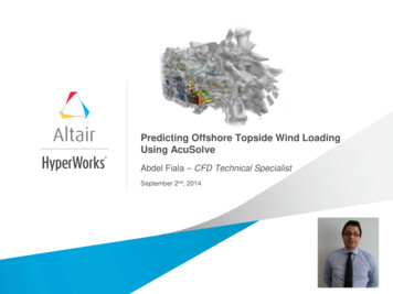
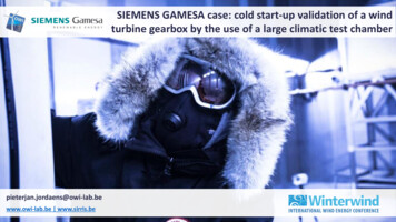
Figure 3-3. Semi-submersible (on the left) and Barge (on the right) floating OSP conceptsSource: Atlantique Offshore EnergyThe different design concepts for floating OSP foundations are similar to those used for wind turbines: semi-submersibles,tension leg platforms (TLP), barge, and spars (see Figure 3-3 and Figure 3-4 for examples of design concepts). The barge,semi-submersible, and spar buoy are moored to the seabed with chains, steel cables, or fiber ropes connected to anchors. ATLP is vertically moored with tethers or tendons (i.e., tension legs). Very strong cables, pipes, or rods link the TLP’s legs toseabed anchoring. Across all types of floating foundations, different anchor types can be used depending on the type ofmooring system, soil conditions, and expected environmental loads.The constraints of an OSP require different designs from the floating foundations used for the wind turbines. First, the OSPtopside can be significantly heavier (2,000 MT to 4,500 MT or more) than a wind turbine ( 1,200 MT for a 12 MW windturbine assembly), and the weight distribution is also very different, with the OSP having a lower center of gravity. Thesefactors directly impact the floater’s stability and seakeeping, requiring different floater dimensions or even different conceptsaltogether. Second, an OSP has a multitude of connected subsea cables, which are sensitive to displacement and cancreate single points of failure.DNV – www.dnv.comPage 8
Figure 3-4. Design concepts for floating substationsSource: DNV3.2.1.1Floating OSP technical challengesWhile many of the components of floating OSP are proven technologies developed for the oil and gas or maritime industries,there are several technical challenges facing floating OSP development: the need for dynamic cables that can connect floatingsubstations to fixed structures, and HV equipment capable of withstanding the stresses inducted by ocean movement. Thesechallenges are being addressed by the equipment manufacturers and are expected to be available for the first commercialfloating offshore wind developments.To link the floating OSP to the shore, the HV export cable needs to be “dynamic,” as it will connect a moving structure (theOSP) to a fixed element (the seabed). Unlike standard HV subsea cables used for bottom-fixed offshore substations, thedynamic cables must be able to accommodate the extreme displacements of the substation during storms and have sufficientfatigue endurance to handle a lifetime of cyclic movements ( 20 years). This kind of dynamic cable currently exists for voltagesup to 66kV, but are still under development for the higher voltages required for power export in commercial-scale projects.One of the primary challenges faced by cable manufacturers is finding an alternative material to the lead sheaths surroundingeach cable core. The lead sheath protects cable cores from moisture ingress but has poor fatigue endurance.The repetitive movements and acceleration generated by a floating platform that is subject to wind and waves requiresadditional innovation in the equipment contained in the platform. This could have an impact on the HV equipment, especiallythe main power transformer and the high voltage gas-insulated switchgear (HV GIS). Although most of the utility systemsand medium-voltage equipment have proven their reliability in the oil & gas and maritime industries, the HV GIS and powertransformers currently in the market have not been designed for the repetitive accelerations anticipated onboard a floatingOSP. Although the equipment is typically designed for seismic motions, this is not directly transferable to floating structures,DNV – www.dnv.comPage 9
which move with larger amplitude and have many more fatigue cycles. New innovations to address the dynamic cable andthe HV equipment need to be qualified and field tested before being implemented in commercial-scale projects.For high voltage direct current (HVDC) main transmission equipment, including power electronics and converter valves,there are major engineering challenges in designing equipment that can function and operate as intended on a floatingfoundation (or on a fixed foundation in deeper water with significant dynamics). This is an area of ongoing research anddevelopment in the industry, but the implementation timeline will likely include significant research efforts and havesignificant associated uncertainties. Floating HVDC substation technologies should therefore likely be available later thanfloating high voltage alternating current (HVAC) technologies, although it is expected that these technologies will beavailable by the time they are needed to deploy for commercial-scale floating offshore wind projects. See Section 3.3 belowfor deeper discussion of the differences between AC vs DC technologies.3.2.2Alternatives to floating OSPThere are several alternatives to floating OSP, including bottom-fixed and subsea OSP concepts.3.2.2.1Deep water fixed foundationsA floating wind farm would typically be installed in depths greater than 60 m, where a bottom-fixed monopile or jacket wouldnot be economically feasible due to the high material (typically steel) and installation costs that would be necessary for eachof the turbines. While commercial-scale floating wind farms can include 50 or more turbines, each wind farm will likelycontain only one or two OSPs, which are specifically designed and built for each project and could leverage bottom-fixedstructures as an approach to mitigate some of the technical challenges mentioned in Section 3.2.1.1. While there are severaltechnically feasible bottom-fixed solutions (see Figure 3-5) for an OSP, a bottom-fixed foundation could potentially becompetitive as deep as approximately 100 m (a depth not unusual for oil & gas fixed platforms). In some areas of the Gulf ofMaine, the water depths could allow for bottom-fixed substations (u
planning delays. Competitive, open processes tend to produce favorable financial results. Selection of onshore POIs should consider numerous factors. Key factors that affect onshore POI selection include the location of the offshore wind areas, grid reliability analyses, nearness of the substation to the shore, cost