Transcription
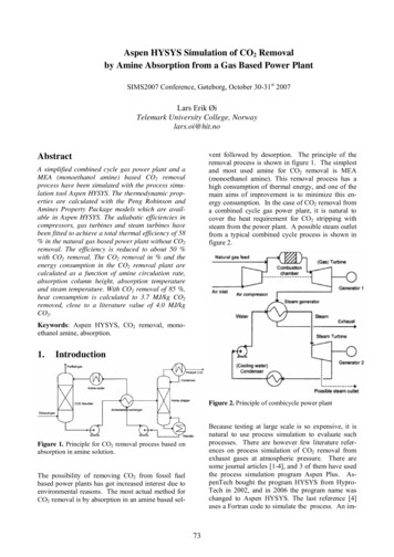
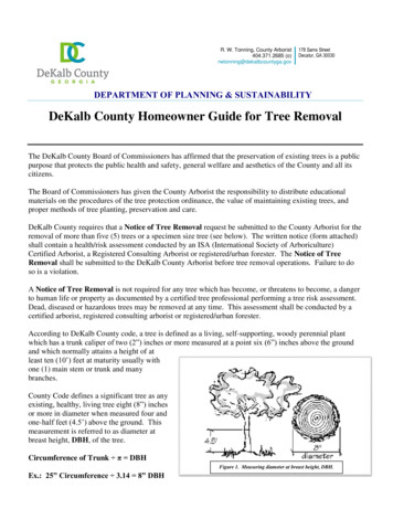
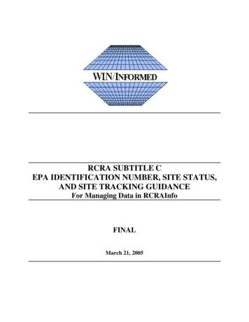
United StatesEnvironmental ProtectionAgencyWastewater Technology Fact SheetScreening and Grit RemovalDESCRIPTIONCoarse ScreensWastewater contains large solids and grit that caninterfere with treatment processes or cause unduemechanical wear and increased maintenance onwastewater treatment equipment. To minimizepotential problems, these materials require separatehandling. Preliminary treatment removes theseconstituents from the influent wastewater.Preliminary treatment consists of screening, gritremoval, septage handling, odor control, and flowequalization. This fact sheet discusses screeningand grit removal.Coarse screens remove large solids, rags, and debrisfrom wastewater, and typically have openings of 6mm (0.25 in) or larger. Types of coarse screensinclude mechanically and manually cleaned barscreens, including trash racks. Table 1 describes thevarious types of coarse screens.ScreeningScreening is the first unit operation used atwastewater treatment plants (WWTPs). Screeningremoves objects such as rags, paper, plastics, andmetals to prevent damage and clogging ofdownstream equipment, piping, and appurtenances.Some modern wastewater treatment plants use bothcoarse screens and fine screens. Figure 1 depicts atypical bar screen (a type of coarse screen).Fine ScreensFine screens are typically used to remove materialthat may create operation and maintenance problemsin downstream processes, particularly in systemsthat lack primary treatment. Typical opening sizesfor fine screens are 1.5 to 6 mm (0.06 to 0.25 in).Very fine screens with openings of 0.2 to 1.5 mm(0.01 to 0.06 in) placed after coarse or fine screenscan reduce suspended solids to levels near thoseachieved by primary clarification.Comminutors and GrindersProcessing coarse solids reduces their size so theycan be removed during downstream treatmentoperations, such as primary clarification, where bothfloating and settleable solids are removed.Comminuting and grinding devices are installed inthe wastewater flow channel to grind and shredmaterial up to 6 to 19 mm (0.25 to 0.75 in) in size.Comminutors consist of a rotating slotted cylinderthrough which wastewater flow passes. Solids thatare too large to pass through the slots are cut byblades as the cylinder rotates, reducing their sizeuntil they pass through the slot openings.Source: Qasim, 1994.FIGURE 1 CABLE OPERATED BARSCREENGrinders consist of two sets of counterrotating,intermeshing cutters that trap and shear wastewatersolids into a consistent particle size, typically 6 mm(0.25 in). The cutters are mounted on two drive
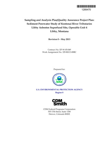
TABLE 1 DESCRIPTION OF COARSESCREENSScreen TypeDescriptionTrash RackDesigned to prevent logs, timbers,stumps, and other large debris fromentering treatment processes.Opening size: 38 to 150 mm (1.5-6 in)ManuallyCleaned BarScreenDesigned to remove large solids, rags,and debris.Opening size: 30 to 50 mm (1 to 2 in)Bars set at 30 to 45 degrees fromvertical to facilitate cleaning.Primarily used in older or smallertreatment facilities, or in bypasschannels.MechanicallyCleaned BarScreenDesigned to remove large solids, rags,and debris.Opening size: 6 to 38 mm (0.25 to 1.5in).Bars set at 0 to 30 degrees fromvertical.Almost always used in newinstallations because of large numberof advantages relative to otherscreens.follow screening and comminution. This preventslarge solids from interfering with grit handlingequipment. In secondary treatment plants withoutprimary clarification, grit removal should precedeaeration (Metcalf & Eddy, 1991).Many types of grit removal systems exist, includingaerated grit chambers, vortex-type (paddle or jetinduced vortex) grit removal systems, detritus tanks(short-term sedimentation basins), horizontal flowgrit chambers (velocity-controlled channel), andhydrocyclones (cyclonic inertial separation).Various factors must be taken into considerationwhen selecting a grit removal process, including thequantity and characteristics of grit, potential adverseeffects on downstream processes, head lossrequirements, space requirements, removalefficiency, organic content, and cost. The type ofgrit removal system chosen for a specific facilityshould be the one that best balances these differentconsiderations. Specifics on the different types ofgrit removal systems are provided below.Source: Design of Municipal Wastewater Treatment Plants,WEF MOP 8, Fourth Edition, 1998.Aerated Grit Chambershafts with intermediate spacers. The shaftscounterrotate at different speeds to clean the cutters.Figure 2 depicts a channel wastewater grinder.In aerated grit chambers, grit is removed by causingthe wastewater to flow in a spiral pattern, as shownThe chopping action of the grinder reduces theformation of rag “balls” and rag “ropes” (aninherent problem with comminutors). Wastewatersthat contain large quantities of rags and solids, suchas prison wastewaters, utilize grinders downstreamfrom coarse screens to help prevent frequentjamming and excessive wear.Grit RemovalGrit includes sand, gravel, cinder, or other heavysolid materials that are “heavier” (higher specificgravity) than the organic biodegradable solids in thewastewater. Grit also includes eggshells, bonechips, seeds, coffee grounds, and large organicparticles, such as food waste. Removal of gritprevents unnecessary abrasion and wear ofmechanical equipment, grit deposition in pipelinesand channels, and accumulation of grit in anaerobicdigesters and aeration basins. Grit removalfacilities typically precede primary clarification, andSource: WEF, 1998.FIGURE 2 WASTEWATER GRINDER:CHANNEL UNIT
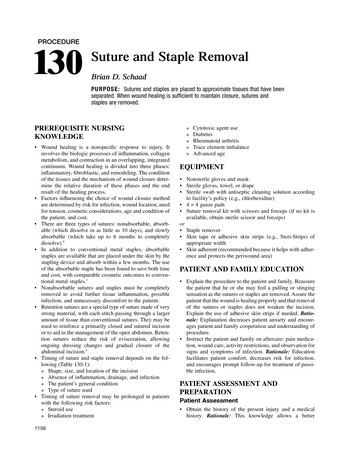
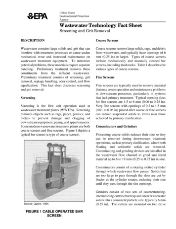
in Figure 3. Air is introduced in the grit chamberalong one side, causing a perpendicular spiralvelocity pattern to flow through the tank. Heavierparticles are accelerated and diverge from thestreamlines, dropping to the bottom of the tank,while lighter organic particles are suspended andeventually carried out of the tank.Parshall flumes. In this system, heavier gritparticles settle to the bottom of the channel, whilelighter organic particles remain suspended or areresuspended and transported out of the channel.Grit is removed by a conveyor with scrapers,buckets, or plows. Screw conveyors or bucketelevators are used to elevate the grit for washing ordisposal. In smaller plants, grit chambers are oftencleaned manually.HydrocycloneSource: Crites and Tchobanoglous, 1998.FIGURE 3 AERATED GRIT CHAMBERHydrocyclone systems are typically used to separategrit from organics in grit slurries or to remove gritfrom primary sludge. Hydrocyclones are sometimesused to remove grit and suspended solids directlyfrom wastewater flow by pumping at a headranging from 3.7 to 9 m (12 to 30 ft). Heavier gritand suspended solids collect on the sides andbottom of the cyclone due to induced centrifugalforces, while scum and lighter solids are removedfrom the center through the top of the cyclone.APPLICABILITYVortex-Type Grit ChamberThe vortex-type grit chamber consists of acylindrical tank in which the flow enterstangentially, creating a vortex flow pattern. Gritsettles by gravity into the bottom of the tank (in agrit hopper) while effluent exits at the top of thetank. The grit that settles into the grit hopper maybe removed by a grit pump or an air lift pump.Because various types of screening and gritremoval devices are available, it is important thatthe proper design be selected for each situation.Though similarities exist between different types ofequipment for a given process, an improperlyapplied design may result in an inefficient treatmentprocess.ScreeningDetritus TankA detritus tank (or square tank degritter) is aconstant-level, short-detention settling tank. Thesetanks require a grit-washing step to remove organicmaterial. One design option includes a grit augerand a rake that removes and classifies grit from thegrit sump.Horizontal Flow Grit ChamberThe horizontal flow grit chamber is the oldest typeof grit removal system. Grit is removed bymaintaining a constant upstream velocity of 0.3 m/s(1 ft/s). Velocity is controlled by proportionalweirs or rectangular control sections, such asAs discussed above, most large facilities usemechanically cleaned screening systems to removelarger materials because they reduce labor costs andthey improve flow conditions and screening capture.Typically, only older or smaller treatment facilitiesuse a manually cleaned screen as the primary oronly screening device. A screening compactor isusually situated close to the mechanically cleanedscreen and compacted screenings are conveyed to adumpster or disposal area. However, plantsutilizing mechanically cleaned screens should havea standby screen to put in operation when theprimary screening device is out of service. This isstandard design practice for most newly designedplants.
The use of fine screens in preliminary treatment hasexperienced a resurgence in the last 20 years. Suchscreens were a common feature before 1930 buttheir use diminished because of difficulty incleaning oils and grease from the screens. In theearly 1980s, fine screens regained popularitybecause of improved materials.screenings. Some recently developed grinders canchop, remove, wash, and compact the screenings.The use of comminutors in cold weather eliminatesthe need to prevent collected screenings fromfreezing. Comminutors and grinders typically havea lower profile than screens, so cost savings can besignificant when the units must be enclosed.Communitors and GrindersGrit RemovalComminutors and grinders are used primarily atsmaller treatment facilities (less than 5 MGD) toprocess material between 6 and 19 mm (0.25 to0.75 in) (WEF, 1998). This shredded materialremains in the wastewater and is removed indownstream treatment processes.Aerated Grit Chamber Consistent removal efficiency over a wideflow range.Grit Removal A relatively low putrescible organic contentmay be removed with a well controlled rateof aeration. Performance of downstream units may beimproved by using pre-aeration to reduceseptic conditions in incoming wastewater. Aerated grit chambers are versatile,allowing for chemical addition, mixing, preaeration, and flocculation.When selecting a grit removal process, the quantityand characteristics of grit and its potential toadversely affect downstream processes areimportant considerations. Other parameters toconsider may include headloss requirements, spacerequirements, removal efficiency, organic content,and economics.Some advantages of aerated grit chambers include:ADVANTAGES AND DISADVANTAGESAdvantagesVortex-Type Grit ChamberScreening These systems remove a high percentage offine grit, up to 73 percent of 140-mesh (0.11mm/0.004 in diameter) size. Vortex grit removal systems have aconsistent removal efficiency over a wideflow range. There are no submerged bearings or partsthat require maintenance. The “footprint” (horizontal dimension) of avortex grit removal system is small relativeto other grit removal systems, making itadvantageous when space is an issue. Headloss through a vortex system isminimal, typically 6 mm (0.25 in). Thesesystems are also energy efficient.Manually cleaned screens require little or noequipment maintenance and provide a goodalternative for smaller plants with few screenings.Mechanically cleaned screens tend to have lowerlabor costs than manually cleaned screens and offerthe advantages of improved flow conditions andscreening capture over manually cleaned screens.Communitors and GrindersA major advantage of using communitors andgrinders is that removal of grit reduces damage andmaintenance to downstream processes.Comminutors and grinders also eliminatescreenings handling and disposal, which mayimprove the aesthetics of the plant, reducing odors,flies, and the unsightliness associated with
Detritus TankGrit RemovalDetritus tanks do not require flow control becauseall bearings and moving mechanical parts are abovethe water line. There is minimal headloss in thistype of unit.Grit removal systems increase the headloss througha wastewater treatment plant, which could beproblematic if headloss is an issue. This couldrequire additional pumping to compensate for theheadloss.Horizontal Flow Grit ChamberHorizontal flow grit chambers are flexible becausethey allow performance to be altered by adjustingthe outlet flow control device. Construction is notcomplicated. Grit that does not require furtherclassification may be removed with effective flowcontrol.HydrocycloneHydrocyclones can remove both grit and suspendedsolids from wastewater. A hydrocyclone canpotentially remove as many solids as a primaryclarifier.The following paragraphs describe the specificdisadvantages of different types of grit removalsystems.Aerated Grit ChamberPotentially harmful volatile organics and odors maybe released from the aerated grit chamber. Aeratedgrit chambers also require more power than othergrit removal processes, and maintenance and controlof the aeration system requires additional labor.Vortex-Type Grit Chamber Vortex grit removal systems are usually of aproprietary design, which makesmodifications difficult. Paddles tend to collect rags. Vortex units usually require deep excavationdue to their depth, increasing constructioncosts, especially if unrippable rock ispresent. The grit sump tends to clog and requireshigh-pressure agitation using water or air toloosen grit compacted in the sump.DisadvantagesScreeningManually cleaned screens require frequent raking toavoid clogging and high backwater levels that causebuildup of a solids mat on the screen. Theincreased raking frequency increases labor costs.Removal of this mat during cleaning may also causeflow surges that can reduce the solids-captureefficiency of downstream units. Mechanicallycleaned screens are not subject to this problem, butthey have high equipment maintenance costs.Communitors and GrindersDetritus TankComminutors and grinders can create problems fordownstream processes, such as increasing plasticsbuildup in digestion tanks or rag accumulation onair diffusers. In addition, solids from comminutorsand grinders will not decompose during thedigestion process. If these synthetic solids are notremoved, they may cause biosolids to be rejectedfor reuse as a soil amendment. Detritus tanks have difficulty achievinguniform flow distribution over a wide rangeof flows because the inlet baffles cannot beadjusted. This type of removal system removes largequantities of organic material, especially atlow flows, and thus requires grit washingand classifying.
Grit may be lost in shallow installations(less than 0.9 m [3 ft]) due to the agitationcreated by the rake arm associated with thissystem.Horizontal Flow Grit ChamberTABLE 2 SCREENING DEVICECLASSIFICATIONScreening DeviceClassificationSize Classification/SizeRange of Screen OpeningBar screenManually CleanedIt is difficult to maintain a 0.3 m/s (1 ft/s)velocity over a wide range of flows.Coarse/25-50 mm(1-2 in)Mechanically CleanedCoarse/15-75 mm(0.6-3.0 in) The submerged chain, flight equipment, andbearings undergo excessive wear.Fine bar or perforated coarse screen (mechanicallycleaned)Fine Bar Channels without effective flow control willremove excessive amounts of organicmaterial that require grit washing andclassifying.Fine Coarse/3-12.5 mm(0.1-0.5 in)Perforated PlateFine Coarse/3-9.5 mm(0.1-0.4 in)Rotary DrumFine Coarse/3-12.5 mm(0.1-0.5 in)Head loss is excessive (typically 30 to 40percent of flow depth).Fine screen (mechanically cleaned)Fixed ParabolicHigh velocities may be generated at thechannel bottom with the use of proportionalweirs, leading to bottom scour.Fine/0.25-3.2 mm(0.01-0.13 in)Rotary DrumFine/0.25-3.2 mm(0.01-0.13 in)Rotary DiskVery fine (micro)/0.15-0.38 mm(0.01-0.02 in) HydrocycloneSource: Crites and Tchobanoglous, 1998.Hydrocyclones require energy because they use apump to remove grit and suspended solids. Coarsescreening is required before these units to removesticks, rags, and plastics.DESIGN CRITERIAScreeningScreening devices are classified based on the size ofthe material they remove (the screenings). The“size” of screening material refers to its diameter.Table 2 lists the correlation between screening sizesand screening device classification.In addition to screening size, other designconsiderations include the depth, width, andapproach velocity of the channel; the dischargeheight, the screen angle; wind and aestheticconsiderations; redundancy; and head loss.Table 3 lists typical design criteria for mechanicallycleaned bar rack type screens.The use of fine screens produces removalcharacteristics similar to primary sludge removal inprimary sedimentation. Fine screens are capable ofremoving 20 to 35 percent suspended solids andBOD5. Fine screens may be either fixed ormovable, but are permanently set in a vertical,inclined, or horizontal position and must be cleanedby rakes, teeth, or brushes.Communitors and GrindersFigure 4 depicts a typical comminutor. Whendesigning a comminutor, headloss should beconsidered. Headloss through a comminutor isusually in the range of a few centimeters to 0.9 m (3ft). Therefore, the manufacturer’s ratings should bedecreased by 70 to 80 percent to account forclogging of the screen, since manufacturer’sheadloss characteristics are usually based on cleanwater flow (Crites and Tchobanoglous, 1998).
TABLE 3 DESIGN CRITERIA FORMECHANICALLY CLEANED BARSCREENSDesign CriteriaItemMetric UnitsEnglish UnitsBar width5-15 mm0.2-0.6 inBar depth25-40 mm1.0-1.5 inClear spacingbetween bars15-75 mm0.6-3.0 inSlope fromvertical0-30 degrees0-30 degreesApproachvelocity0.6-1.0 m/s2.0-3.25 ft/sAllowableHeadloss150 mm6 inSource: WEF, 1998.When a comminution device is installed upstreamof a grit removal device, the teeth of thecomminutor are subject to high wear and tear.Rock traps are recommended to prolong the life ofthe comminutor. In addition, a bypass manual barrack should be installed in the event that flow ratesexceed the comminutor capacity or there is amechanical failure.Grit RemovalWith respect to grit removal systems, grit istraditionally defined as particles larger than 0.21mm (0.008 in) (65 mesh) and with a specific gravityof greater than 2.65 (U.S. EPA, 1987). Equipmentdesign was traditionally based on removal of 95percent of these particles. However, with the recentrecognition that smaller particles must be removedto avoid damaging downstream processes, manymodern grit removal designs are capable ofremoving up to 75 percent of 0.15 mm (0.006 in)(100 mesh) material.Aerated Grit ChamberAerated grit chambers are typically designed toremove particles of 70 mesh (0.21 mm/0.008 in) orlarger, with a detention period of two to fiveminutes at peak hourly flow. When wastewaterflows into the grit chamber, particles settle to thebottom according to their size, specific gravity, andthe velocity of roll in the tank. A velocity that is toohigh will result in lower grit removal efficiencies,while a velocity that is too low will result inincreased removal of organic materials. Properadjustment of air velocity will result in nearly 100percent removal of the desired particle size and awell-washed grit.Design considerations for aerated grit chambersinclude the following (WEF 1998):Source: Reynolds/Richards, 1996.FIGURE 4 TYPICAL COMMINUTOR INSTALLATION
Air rates typically range from 0.3 to 0.7m3/m min (3 to 8 ft3/ft .min) of tank length. A typical minimum hydraulic detentiontime at maximum instantaneous flow is twominutes. Typical length-to-width ratio is 2.5:1 to 5:1.of the target grit particles and the flow controlsection-depth relationship. An allowance for inletand outlet turbulence is added. The cross sectionalarea of the channel is determined by the rate of flowand the number of channels. Allowances are madefor grit storage and grit removal equipment. Table4 lists design criteria for horizontal flow gritchambers. Tank inlet and outlet are positioned so theflow is perpendicular to the spiral rollpattern.TABLE 4 HORIZONTAL FLOW GRITCHAMBER DESIGN CRITERIA Baffles are used to dissipate energy andminimize short circuiting.Design CriteriaRange Metric(English)TypicalMetric(English)45-90 s60 s0.24-0.4 m/s(0.8-1.3 ft/s)0.3 m/s(1.0 ft/s)50-mesh2.8-3.1 m/min(9.2-10.2 ft/min)2.9 m/min(9.6 ft/min)100-mesh0.6-0.9 m/min(2.0-3.0 ft/min)0.8 m/min(2.5 ft/min)Headloss (% ofchannel depth)30-40%36%2Inlet and outletlength allowance25-50%30%ItemVortex-Type Grit ChamberDetention timeTwo designs of vortex grit units exist: chamberswith flat bottoms and a small opening to collectgrit; and chambers with a sloping bottom and alarge opening into the grit hopper. Flow into avortex-type grit system should be straight, smooth,and streamlined. The straight inlet channel lengthis typically seven times the width of the inletchannel, or 4.6 m (15 ft), whichever is greater. Theideal velocity range in the influent is typically 0.6 to0.9 m/s (2 to 3 ft/s) at 40 to 80 percent of peakflow. A minimum velocity of 0.15 m/s (0.5 ft/s)should be maintained at all times, because lowervelocities will not carry grit into the grit chamber(WEF, 1998).Detritus TankDetritus tanks are designed to keep horizontalvelocity and turbulence at a minimum whilemaintaining a detention time of less than oneminute. Proper operation of a detritus tank dependson well-distributed flow into the settling basin.Allowances are made for inlet and outlet turbulenceas well as short circuiting by applying a safetyfactor of 2.0 to the calculated overflow rate.Horizontal Flow Grit ChamberHorizontal flow grit chambers use proportionalweirs or rectangular control sections to vary thedepth of flow and keep the velocity of the flowstream at a constant 0.3 m/s (1 ft/s). The length ofthe grit chamber is governed by the settling velocityHorizontal velocitySettling velocity1:1If the specific gravity of the grit is significantly less than 2.65,lower velocities should be used.2For Parshall flume control.Source: Crites and Tchobanoglous, 1998.PERFORMANCEThe use of screening and grit removal systems iswell documented. The performance of bar screensvaries depending on the spacing of the bars. Table5 lists typical screening quantities for various screensizes.The quantity of screenings depends on the lengthand slope of the collection system and the presenceof pumping stations. When the collection system islong and steep or when pumping stations exist,fewer screenings are produced because ofdisintegration of solids. Other factors that affectscreening quantities are related to flow, as quantitiesgenerally increase greatly during storm flows. Peak
Table 6 depicts quantities of screenings and gritfrom various wastewater treatment plants. Thereare no obvious trends associated with design flowthrough a plant and grit and screenings removalquantities. Differences in wastewater characteristicsand equipment efficiencies make a correlationbetween flow and quantities of screenings and gritremoved nearly impossible.TABLE 5 SCREENING REMOVALQUANTITIESScreenings QuantityScreen Sizem3/106 m3ft3/Mgal13 mm (0.5 in)60838 mm (1.5 in)11.21.5Source: Reynolds and Richards, 1996.OPERATION AND MAINTENANCEdaily removals may vary by a 20:1 ratio on anhourly basis from average flow conditions.Combined collection systems may produce severaltimes the coarse screenings produced by separatecollection systems.Given the complexity of collection systems andtypes of materials that may be considered “grit,” thequantity and characteristics of grit removed fromwastewater will vary. Grit quantity is influenced bythe type and condition of the collection system, thecharacteristics of the drainage area, garbagedisposal methods, the slope of the collectionsystem, and the efficiency of the grit removalsystem. The quantity of grit may vary from 0.004to 0.21 m3/103m3 (0.5 to 30 ft3/Mgal) (Crites andTchobanoglous, 1998). The performance of a gritremoval system may be enhanced if actual plantdata is used when designing a new grit removalsystem.ScreeningManually cleaned screens require frequent raking toprevent clogging. Cleaning frequency depends onthe characteristics of the wastewater entering aplant. Some plants have incorporated screeningdevices, such as basket-type trash racks, that aremanually hoisted and cleaned. Mechanicallycleaned screens usually require less labor foroperation than manually cleaned screens becausescreenings are raked with a mechanical devicerather than by facility personnel. However, the raketeeth on mechanically cleaned screens must beroutinely inspected because of their susceptibility tobreakage and bending. Drive mechanisms must alsobe frequently inspected to prevent fouling due to gritand rags. Grit removed from screens must bedisposed of regularly.TABLE 6 GRIT AND SCREENINGS REMOVAL QUANTITIES AT VARIOUS PLANTSPlant LocationFlow, m3/d(MGD)Grit, m3/103m3(ft3/Mgal)Screenings,m3/103m3 (ft3/Mgal)aUniontown, Pennsylvania11,400 (3.0)0.074 (10.5)0.006 (0.9)East Hartford, Connecticut15,100 (4.0)0.017 (2.4)0.009 (1.33)Duluth, Minnesota45,400 (12.0)0.006 (0.8)0.004 (0.56)Lamberts Point Water Pollution Control Plant,Norfolk, Virginia75,700 (20.0)0.034 (4.85)0.009 (1.20)Village Creek Wastewater Treatment Plant,Ft. Worth, Texas170,000 (45.0)0.009 (1.29)0.005 (0.72)County of Milwaukee, Wisconsin, South Shore454,000 (120.0)0.003 (0.48)0.004 (0.60)Twin Cities Metro Wastewater Treatment Plant,Minnesota825,000 (218.0)0.034 (4.82)0.008 (1.15)1,260,000 (333.0)0.003 (0.41)0.006 (0.83)Chicago, Illinois (Northside)ft /Mgal cubic feet per million gallonsa 3Source: WEF, 1998.
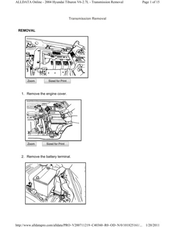
Communitors and Grindersequipment, and applicability of various technologiesto different situations.Comminutors can create operation and maintenanceproblems in downstream processes.Whileshredding solids eliminates the problem of handlingscreening materials at the head of the plant,problems inherent to the use of communitors, suchas the decreased quality of digested biosolids andthe accumulation of rags on air diffusers, havelessened the popularity of this technology.Comminutors are generally avoided in new designsand are being removed from many existing plants.Grinders are greatly affected by grit and othersolids. As such, they require routine inspectionevery six months and replacement of bearings andcutter teeth every one to three years.Graphs can be used to relate average wastewaterflow through a plant to a specific technology.Figure 5 shows a graph relating wastewater flow tothe cost of a horizontal shaft rotary screen. Costsinclude construction, operation, and maintenance.Contractor bids on a recent wastewater projectranged from 150,000 to 400,000 for Rotary DrumScreenings Removal and from 150,000 to 208,800 for Vortex-type Grit Removals.Generally, equipment costs will be close for eachbid. However, the overall costs vary for eachtreatment process/project because of differences inconstruction approaches by the contractors.Grit RemovalREFERENCESCollected grit must be removed from the chamber,dewatered, washed, and conveyed to a disposal site.Some smaller plants use manual methods to removegrit, but grit removal is usually accomplished by anautomatic method. The four methods of automaticgrit removal include inclined screw or tubularconveyors, chain and bucket elevators, clamshellbuckets, and pumping. A two-step grit removalmethod is sometimes used, where grit is conveyedhorizontally in a trough or channel to a hopper,where it is then elevated from the hopper to anotherlocation.Other Related Fact SheetsAerated grit chambers use a sloped tank bottom inwhich the air roll pattern sweeps grit along thebottom to the low side of the chamber. Ahorizontal screw conveyor is typically used toconvey settled grit to a hopper at the head of thetank. Another method to remove grit from thechamber floor is a chain and flight mechanism.Once removed from the chamber, grit is usuallywashed with a hydrocyclone or grit classifier to easehandling and remove organic material. The grit isthen conveyed directly to a truck, dumpster, orstorage hopper. From there, the grit is taken to alandfill or other disposal facility.COSTSThe cost of screens and grit removal systems variesdepending on the type of technology used, ancillary110.1Annual O&MConstruction Cost-Millions of Dollars100.10.010.010.110.00110010Wastewater Flow MGDConstruction CostAnnual O&MSource: Martin, 1991.FIGURE 5 COST CURVE FORHORIZONTAL SHAFT ROTARY SCREENSewer Lift StationEPA 832-F-00-073September 2000Sewer Cleaning & InspectionEPA 832-F-99-031September 1999
ScreensEPA 832-F-99-040September 1999Lakeside Equipment Corporation1022 E. Devon Ave.Bartlett, IL 60103Other EPA Fact Sheets can be found at thefollowing web onal Small Flows Clearing Houseat West Virginia UniversityP.O. Box 6064Morgantown, WV 265061.2.3.4.5.6.Crites, R. and G. Tchobanoglous, 1998.Small and Decentralized WastewaterManagement Systems. The McGraw-HillCompanies. Boston, Massachusetts.Martin, E.J. and E.T. Martin, 1991.Technologies for Small Water andWastewater Systems.Van NostrandReinhold. New York, New York.Qasim, S., 1994. Wastewater TreatmentPlants: Planning, Design and Operation.Technomic Publishing Co., Lancaster,Pennsylvania.Reynolds, T. and P. Richards, 1996. UnitOperations and Processes in EnvironmentalEngineering. PWS Publishing Company.Boston, Massachusetts.Urquhart, L., 1962. Civil Engineering.Costs include construction, operation, andmaintenance. Specific cost data fromcontractor bids.Water Environment Federation, 1998.Design of Municipal Wastewater TreatmentPlants. Water Environment Federation.Alexandria, Virginia.ADDITIONAL INFORMATIONH.I.L. Technology, Inc.94 Hutchins DrivePortland, ME 04102Parkson Corporation2727 NW 62nd StreetP.O. Box 408399Fort Lauderdale, FL 33340-8399U.S. FilterLink-Belt Headworks Products100 High Point Drive - Suite 101Chalfont, PA 18914The mention of trade names or commercial productsdoes not constitute endorsement or recommendationfor use by the U.S. Environmental ProtectionAgency (EPA).Office of WaterE
Vortex grit removal systems have a consistent removal efficiency over a wide flow range. There are no submerged bearings or parts that require maintenance. The "footprint" (horizontal dimension) of a vortex grit removal system is small relative to other grit removal systems, making it advantageous when space is an issue.