Transcription
ODYSSEY Shop ChargerModels: OSC-70AOSC-105AAUTOMATIC BATTERY CHARGERInstruction ManualTo automatically be connected to your closest Service Center, call us toll-free at:1-800-ENERSYS (1-800-363-7797)AM-OSC3BAY-IMRev AA August 2019IMPORTANTRead and understand your instruction manual before installing, operating or servicing thisproduct.DO NOT DESTROY THIS MANUAL, SAVE IT FOR FUTURE REFERENCE
ODYSSEY ShopChargerInstruction ManualAM-OSC3BAY-IMRev AA August 2019TABLE OF CONTENTSSafety Guidelines/Definitions . 2Important Safety Instructions . 2Technical Information. 9UL Model and Part Number. 9UL Model Number . 9Part Number . 9Output Power Letter Codes . 9Cabinet Size Letter Code . 10DC Voltage Number Code . 10Input Voltage Letter Code . 10Serial Number . 10Battery Type . 10Modules . 10AC Volts . 10AC Amps. 10Hertz . 11Phase . 11DC Amps . 11DC Volts. 11CEC . 11cULus . 11FCC . 11Introduction. 12AC Power Fail . 12Series Charging . 12Charging Profile . 12ODY Profile . 12Equalization Charging . 12Refresh Charging . 12Features. 13Control Panel . 13Installation. 14Charger Location . 14Shelf Mounting . 14DC Plug Polarity. 14Assembly Instructions . 14Preparing the Charger . 15Connecting AC Power . 15Main Menu . 16Logs . 17Memorizations Display Screen . 17Displaying a Charge Cycle . 17Memorization Data . 17Status . 18Status Screen. 18Charger . 19Information . 19USB . 20Update Software . 20Settings . 20Parameters . 20Date/Hour . 20Language . 20Region . 20Display . 20Screen Saver . 20Delay . 20Themes . 21Daylight Saving . 22Password . 22Starting the Charge Cycle. 23Connecting to the Battery . 23Delayed Start. 23Count Down Display . 23Charger Display. 24End of Charge Display. 25End of Charge . 25Disconnecting the Battery . 26Fault Codes . 27Fault Display . 27Maintenance Instructions . 29Moving and Storage Instructions . 29Cabinet Mounting Dimensions . 30Technical Specifications. 31Fuse Replacement. 32Maintenance Log . 331
ODYSSEY ShopChargerInstruction ManualAM-OSC3BAY-IMRev AA August 2019SAFETY GUIDELINES / DEFINITIONSDANGER: Indicates an imminently hazardous situation which, if not avoided, will result in death or serious injury.WARNING: Indicates a potentially hazardous situation which, if not avoided, could result in death or serious injury.CAUTION: Indicates a potentially hazardous situation which, if not avoided, may result in minor or moderate injury,and in property damage.RISK OF UNSAFE OPERATION. When using any tools or equipment, basic safetyprecautions must be followed to reduce the risk of personal injury. Improper operation,maintenance or modification of this charger could result in serious injury and propertydamage. This charger is designed for a specific application. EnerSys stronglyrecommends that this product NOT be modified and/or used for any application otherthan for which it was designed. Read and understand all warnings and operatinginstructions before using this equipment.IMPORTANT SAFETY INSTRUCTIONS SAVE THESE INSTRUCTIONS - This manual contains important safety and operatinginstructions for this battery charger. Before using the battery charger, read all instructions,cautions and warnings on the battery charger, the battery and the product using thebattery.Do not expose charger to rain or snow. The charger is not for outdoor use.Use of an attachment not recommended or sold by the battery charger manufacturer mayresult in a risk of fire, electric shock or injury to persons.To reduce risk of damage to electric plug and cord, pull by plug rather than cord whendisconnecting charger.An extension cord should not be used unless absolutely necessary. Use of improperextension cord could result in a risk of fire and electric shock. If an extension cord mustbe used, make sure:1) That pins on plug of extension cord are the same number, size and shape asthose of plug on charger;2) That extension cord is properly wired and in good electrical condition; and3) That wire size is large enough for AC ampere rating of charger as specified below:2
ODYSSEY ShopChargerInstruction ManualAC input rating, amperesEqual to or greater thanBut less than810121410121416 AM-OSC3BAY-IMRev AA August 2019AWG size of cordLength of cord, feet 816121081612108Do not operate charger with damaged cord or plug - replace the cord or plug immediately.Do not operate charger if it has received a sharp blow, been dropped or otherwisedamaged in any way; return to manufacturer.Do not disassemble charger; contact manufacturer when service or repair is required.Incorrect reassembly may result in a risk of electric shock or fire.To reduce risk of electric shock, unplug charger from outlet before attempting anymaintenance or cleaning. Turning off controls will not reduce this risk.This charger has been designed to charge lead acid batteries. Read and understand allsetup and operating instructions before using the battery charger to prevent damage tothe battery and to the charger.Do not connect or disconnect the battery plug while the charger is on. Doing so will causearcing and burning of the connector resulting in charger damage or battery explosion.Do not expose the charger to moisture. Operating conditions should be 32º to 113º F (0º to 45ºC); 0 to 70% relative humidity.For continued protection and to reduce the risk of fire, install chargers on a floor of noncombustible material such as stone, brick or grounded metal.WARNING - RISK OF EXPLOSIVE GASES.1) WORKING IN VICINITY OF A LEAD ACID BATTERY IS DANGEROUS.BATTERIES GENERATE EXPLOSIVE GASES DURING NORMAL BATTERYOPERATION. FOR THIS REASON, IT IS OF UTMOST IMPORTANCE THAT YOUFOLLOW THE INSTRUCTIONS EACH TIME YOU USE THE CHARGER.2) To reduce risk of battery explosion, follow these instructions and those publishedby battery manufacturer and manufacturer of any equipment you intend to use invicinity of battery. Review cautionary marking on these products and on engine.3
ODYSSEY ShopCharger Instruction ManualAM-OSC3BAY-IMRev AA August 2019PERSONAL PRECAUTIONS1) Consider having someone close by to come to your aid when you work near alead acid battery.2) Have plenty of fresh water and soap nearby in case battery acid contacts skin,clothing or eyes.3) Wear complete eye protection and clothing protection. Avoid touching eyes whileworking near battery.4) If battery acid contacts skin or clothing, wash immediately with soap and water. Ifacid enters eye, immediately flood eye with running cold water for at least 10minutes and get medical attention immediately.5) NEVER smoke or allow a spark or flame in vicinity of battery or engine.6) Be extra cautious to reduce risk of dropping a metal tool onto battery. It mightspark or short-circuit battery or other electrical part that may cause explosion.7) Remove personal metal items such as rings, bracelets, necklaces and watcheswhen working with a lead acid battery. A lead acid battery can produce a shortcircuit current high enough to weld a ring or the like to metal, causing a severe burn.8) Use charger for charging a LEAD ACID battery only. It is not intended to supplypower to a low voltage electrical system other than in a starter-motor application. Donot use battery charger for charging dry-cell batteries that are commonly used withhome appliances. These batteries may burst and cause injury to persons anddamage to property.9) Lead acid batteries contain sulfuric acid, which causes burns. Do not get in eyes,on skin, or on clothing. In cases of contact with eyes, flush immediately with cleanwater for 15 minutes. Seek medical attention immediately.10) NEVER charge a frozen battery. PREPARING TO CHARGE1) If necessary to remove battery from vehicle to charge, always remove groundedterminal from battery first. Make sure all accessories in the vehicle are off, so as notto cause an arc.2) Be sure area around battery is well ventilated while battery is being charged.3) Clean battery terminals. Be careful to keep corrosion from coming in contact witheyes.4
ODYSSEY ShopChargerInstruction ManualAM-OSC3BAY-IMRev AA August 20194) Add distilled water in each cell when needed as specified by batterymanufacturer. Do not overfill. For a battery without removable cell caps, such asvalve regulated lead acid batteries, carefully follow manufacturer's recharginginstructions.5) Study all battery manufacturer's specific precautions while charging andrecommended rates of charge.6) Determine voltage of battery by referring to car owner's manual and make sure itmatches output rating of battery charger. DC CONNECTION PRECAUTIONS1) Connect and disconnect DC output clips only after setting any charger switches to"off" position and removing AC cord from electric outlet. Never allow clips to toucheach other.2) Attach clips to battery and chassis as indicated in sections 5 and 6 for batteryinstalled in vehicle, and sections 2 through 4 for battery outside vehicle. FOLLOW THESE STEPS WHEN BATTERY IS INSTALLED IN VEHICLE. A SPARKNEAR BATTERY MAY CAUSE BATTERY EXPLOSION. TO REDUCE RISK OF ASPARK NEAR BATTERY:1) Position AC and DC cords to reduce risk of damage by hood, door or movingengine part.2) Stay clear of fan blades, belts, pulleys and other parts that can cause injury topersons.3) Check polarity of battery posts. POSITIVE (POS, P, ) battery post usually haslarger diameter than NEGATIVE (NEG, N, - ) post.4) Determine which post of battery is grounded (connected) to the chassis. Ifnegative post is grounded to chassis (as in most vehicles), see section 5. If positivepost is grounded to the chassis, see section 6.5) For negative-grounded vehicle, connect POSITIVE (RED) clip from batterycharger to POSITIVE (POS, P, ) ungrounded post of battery. Connect NEGATIVE(BLACK) clip to vehicle chassis or engine block away from battery. Do not connectclip to carburetor, fuel lines or sheet-metal body parts. Connect to a heavy gagemetal part of the frame or engine block.6) For positive-grounded vehicle, connect NEGATIVE (BLACK) clip from batterycharger to NEGATIVE (NEG, N, - ) ungrounded post of battery. Connect POSITIVE(RED) clip to vehicle chassis or engine block away from battery. Do not connect clip5
ODYSSEY ShopChargerInstruction ManualAM-OSC3BAY-IMRev AA August 2019to carburetor, fuel lines, or sheet-metal body parts. Connect to a heavy gauge metalpart of the frame or engine block.7) When disconnecting charger, turn switches to off, disconnect AC cord, removeclip from vehicle chassis and then remove clip from battery terminal.8) See operating instructions for length of charge information. FOLLOW THESE STEPS WHEN BATTERY IS OUTSIDE VEHICLE. A SPARK NEARTHE BATTERY MAY CAUSE BATTERY EXPLOSION. TO REDUCE RISK OF ASPARK NEAR BATTERY:1) Check polarity of battery posts. POSITIVE (POS, P, ) battery post usually has alarger diameter than NEGATIVE (NEG, N, - ) post.2) Attach at least a 24-inch-long 6-gauge (AWG) insulated battery cable toNEGATIVE (NEG, N, - ) battery post.3) Connect POSITIVE (RED) charger clip to POSITIVE (POS, P, ) post of battery.4) Position yourself and free end of cable as far away from battery as possible thenconnect NEGATIVE (BLACK) charger clip to free end of cable.5) Do not face battery when making final connection.6) When disconnecting charger, always do so in reverse sequence of connectingprocedure and break first connection while as far away from battery as practical.7) A marine (boat) battery must be removed and charged on shore. To charge it onboard requires equipment specially designed for marine use. GROUNDING AND AC POWER CORD CONNECTION INSTRUCTIONSCharger should be grounded to reduce risk of electric shock. Charger is equipped withan electric cord having an equipment-grounding conductor and a grounding plug. Theplug must be plugged into an outlet that is properly installed and grounded inaccordance with all local codes and ordinances.DANGER:Never alter AC cord or plug provided - if it will not fit outlet, have proper outlet installed by aqualified electrician. Improper connection can result in a risk of an electric shock.6
ODYSSEY ShopChargerInstruction ManualAM-OSC3BAY-IMRev AA August 20191) For model OSC-70A, this battery charger is for use on a nominal 120-volt circuit, andhas a grounding plug that looks like the plug illustrated in sketch (A) below. Atemporary adapter, which looks like the adapter illustrated in sketches (B) and (C),may be used to connect this plug to a two-pole receptacle as shown in sketch B if aproperly grounded outlet is not available. The temporary adapter should be usedonly until a properly grounded outlet can be installed by a qualified electrician.DANGER:Before using adapter as illustrated, be certain that center screw of outlet plate isgrounded. The green-colored rigid ear or lug extending from adapter must be connectedto a properly grounded outlet - make certain it is grounded. If necessary, replace originaloutlet cover plate screw with a longer screw that will secure adapter ear or lug to outletcover plate and make ground connection to grounded outlet.2) For model OSC-105A, this battery charger is rated more than 15 amperes and is foruse on a circuit having a nominal rating of 120 volts and is factory-equipped with aspecific electric cord and plug to permit connection to an acceptable electric circuit.Make sure that the charger is connected to an outlet having the same configurationas the plug. No adapter should be used with this charger.7
ODYSSEY ShopChargerInstruction ManualAM-OSC3BAY-IMRev AA August 20193) For a permanently connected battery charger:GROUNDING INSTRUCTIONS - This battery charger should be connected to agrounded, metal, permanent wiring system; or an equipment-grounding conductorshould be run with circuit conductors and connected to equipment-groundingterminal or lead on battery charger. Connections to battery charger should complywith all local codes and ordinances.4) For a direct plug-in battery charger provided with a grounding pin:CAUTION:Risk of Fire or Electric Shock. Connect battery charger directly to groundingreceptacle (three-prong). An adapter should not be used with battery charger.5) For a direct plug-in battery charger having a tab for semi-permanent installation:Use only with duplex receptacle having center screw;Secure unit in place by receptacle cover screw;CAUTION:Risk of Electric Shock or Fire. Disconnect power to receptacle before installing orremoving unit. When removing receptacle-cover screw, cover may fall across plugpins or receptacle may become displaced.6) For a commercial battery charger that is intended to be permanently installed, thisbattery charger should be installed so that it is not likely to be contacted by people.WARNING: The shipping and packing materials must be removed for proper and safe operation.Any data, descriptions or specifications set forth herein are subject to change without notice. Before using theproduct(s), the user is advised and cautioned to make its own determination and assessment of the suitability ofthe product(s) for the specific use in question and is further advised against relying on the information containedherein as it may relate to any general use or indistinct application. It is the ultimate responsibility of the user toensure that the product is suited and the information is applicable to the user’s specific application. Theproduct(s) featured herein will be used under conditions beyond the manufacturer’s control and therefore allwarranties, either express or implied, concerning the fitness or suitability of such product(s) for any particular useor in any specific application, are disclaimed. The user expressly assumes all risk and liability, whether based incontract, tort or otherwise, in connection with the use of the information contained herein or the product itself.8
ODYSSEY ShopChargerAM-OSC3BAY-IMRev AA August 2019Instruction ManualTECHNICAL INFORMATIONThe nameplate located on the outside of the charger should be used to check this applicationbefore installation. The nameplate includes the UL Model number, part number and the ratingsof the cabinet at its full capacity.UL Model Number and Part NumberThe UL Model Number specifies the characteristics of this charger, while the Part Number isequivalent in characteristics to the UL Model Number and given by the manufacturer. The Partnumber and UL Model number are required in any discussion or correspondence regarding thischarger.UL Model Number:OSC1 - CM - 1AModel TypePhaseOutput Power LevelCabinet SizeDC Voltage CodeInput Voltage CodePart Number:OSC – 105AModel TypeDC AmpsAmperesOutput Power Level CodesThe following table describes the letter codes to be used in charger Model number to indicatethe Output Power of the charger.LetterCodeBCChargerNumber ofOutput PowerModules(W)10002150039Module Power(W)500500
ODYSSEY ShopChargerAM-OSC3BAY-IMRev AA August 2019Instruction ManualCabinet Size Letter CodeThe following table describes the letter code to be used in charger Model number to indicate thenumber of slots and size of the DC cables.LetterCodeMModuleCapacity3DC Cable SizeComments4 AWGThree slot, 1 kW module cabinetDC Voltage Number CodeThe following table describes the number code to be used in charger Model number to indicatethe DC output voltage of the charger.NumberCode1OutputVoltage12Input Voltage Letter CodeThe following table describes the letter code to be used in charger Model number to indicate theAC line voltage and AC line frequency at which the charger can be operated.LetterCodeVoltage(Volts RMS)A120LineFrequency(Hertz)50/60Comment120 VAC onlySerial NumberThis is the serial number that contains complete information about the charger. It must besupplied with the part/model number on any correspondence or discussion regarding thischarger.Battery TypeThe chemical content construction of the battery this unit is designed to charge is given in thispart of the nameplate. (L-A Lead Acid)ModulesThis is the number of modules installed in this cabinet.AC VoltsThis is the nominal voltage this charger is rated for. The charger will only operate on this voltage.AC AmpsThis is the AC Amps current rating of this charger.10
ODYSSEY ShopChargerInstruction ManualAM-OSC3BAY-IMRev AA August 2019HertzThis gives the frequency in cycles per second of the AC input voltage. Under no conditionsoperate the charger at a different frequency or from a generator with unstable frequency.PhaseNumber “1” indicates a Single Phase Charger.DC AmpsThis is the DC current that this charger will deliver to a discharged battery with the number ofpower modules installed.DC VoltsThis gives the nominal DC output voltage of the charger.CECThis logo is applied to chargers that are certified with the California Energy Commission incompliance with Appliance Efficiency Regulations:cULusThis logo is applied to chargers that have been tested to applicable standards and requirementsby Underwriters Laboratories (UL) and the Canadian Standards Association (CSA):FCCThis logo is applied to chargers that have wireless communication and comply with the FederalCommunications Commission (FCC):11
ODYSSEY ShopChargerInstruction ManualAM-OSC3BAY-IMRev AA August 2019INTRODUCTIONThe ODYSSEY chargers are compatible with 12V batteries. Battery recognition (voltage,capacity and state of charge) is accomplished automatically by the microprocessor.Furthermore, equalization and refresh charges are integrated.ODYSSEY chargers are microprocessor-controlled. The processor is programmable to adapt tothe battery capacity so that the charging profile can accurately adjust for the battery size. Thecharging coefficient is maintained at various discharge levels.AC Power FailIf the AC power fails with a battery connected to the charger during a charge cycle, the chargerwill reset and start a new charge cycle when power is restored. All charger settings as well asthe time and date are preserved.Series ChargingIn series charging, the voltages of both batteries add up and must match charger’s nameplateDC Volts rating. The charger’s ampere-hour rating must be equal to each of the battery’sampere-hour rating. Charge cycle will not start unless both batteries are connected.Charging ProfileThe charging profile defines the rate of current charge over time. The charger adapts to thebattery’s age and level of discharge. Controlling the overcharge coefficient, whatever thebattery’s discharge level, reduces the amount of electricity consumed.ODY ProfileThis is a charging profile that allows the configuration of the charger for use with ODYSSEYbatteries and flooded automotive batteries. The profile is an IE (constant current, constantvoltage) type with a number of user configurable parameters.Equalization ChargingEqualization charging, performed after normal charging, balances the electrolyte densities in thebattery’s cells.Refresh ChargingRefresh or maintenance charging enables the battery to be maintained at maximum charge allthe time while connected to the charger.12
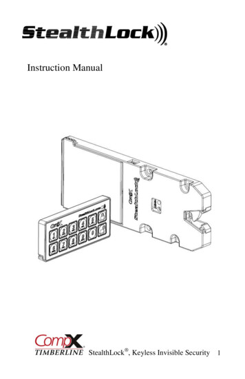
ODYSSEY ShopChargerAM-OSC3BAY-IMRev AA August 2019Instruction ManualFEATURESControl Panel1023145789116RefFunctionDescription1Graphical TFT displayDisplay charger operation info/Menus2Navigate UP buttonNavigate menus/Change values3ENTER/STOP and START buttonSelect menu items/Enter values/Stop andrestart battery charge4Navigate RIGHT/EQUALIZE buttonScroll right/Start equalize or desulfation5Navigation DOWN buttonNavigate menus/Change values6Navigation LEFT/ESC button7RED fault indicator8YELLOW charging indicator9GREEN charge complete indicator10BLUE AC supply indicatorEnter Main Menu/Scroll left/Exit menusOFF no fault, ON faultFLASHING ongoing fault detectedOFF charger output is offON charging in progressOFF charger off or battery not availableFlashing cooling phaseON battery ready and availableOFF AC missing, ON AC present11USB portDownload memos/Upload software13
ODYSSEY ShopChargerInstruction ManualAM-OSC3BAY-IMRev AA August 2019INSTALLATIONWARNING: The shipping packaging and materials must be removed for proper and safeoperationCharger Location Locate charger as far away from battery as DC cables permit.Never place charger directly above battery being charged; gases from battery willcorrode and damage charger.Never allow battery acid to drip on charger when reading electrolyte specific gravity orfilling battery.Do not operate charger in a closed-in area or restrict ventilation in any way.Do not set a battery on top of charger.For maximum safe operation, choose a location which is free of excess moisture, dust,combustible material and corrosive fumes. Also, avoid locations where temperatures arehigh or where liquids will drip on the charger. Do not mount charger on or over acombustible surface. The recommended charger mounting location should provide aradial distance of at least 28 inches away from the closest top edge of the battery.Shelf Mounting The charger may be mounted on a wall, stand, shelf, cart or floor in a vertical position.The minimum distance between two chargers must be 12 inches.The charger may be installed with the brackets supplied. See the Mounting Dimensionssection at the end of this manual for proper bolt pattern.DC Plug PolarityThe charger’s battery cables/clamps are connected to the DC output of the charger and arecolor-coded. Red is positive; black is negative.NOTE: Ambient temperature at all levels cannot exceed 113 F (45 C).ASSEMBLY INSTRUCTIONSIf charger is provided with a DC Clamps cord assembly, connect the DC connector side of thecord assembly to the DC connector of the charger. Make sure the connector’s polarity andcable colors match before making the connection. Never allow clamps to touch each other.14
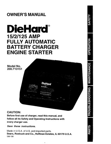
ODYSSEY ShopChargerAM-OSC3BAY-IMRev AA August 2019Instruction ManualPREPARING THE CHARGERConnecting AC PowerCAUTION: Read Important Safety Instructions section related to AC Power Cord.Plug the charger AC grounded power cord into a 120-volt AC outlet with appropriate voltage andamperage rating. With the charger in idle mode (no battery connected) and without pressing anybutton, the display will show the following information:12345Ref12345DescriptionCharger DC VoltageFirmware VersionSelected Charge ProfileSystem Time and DateConnect BatteryS1115
ODYSSEY ShopChargerInstruction ManualAM-OSC3BAY-IMRev AA August 2019Main MenuWhen the charger is idle mode, press and hold ESC , the Main Menu shown below isdisplayed. The main menu is automatically exited after 60 seconds of inactivity or can be exitedvoluntarily by pressing the ESC button.All menus are accessed from Main Menu page; a detailed description of each menu is explainedin the next sections of this manual. The menus that require a password are not displayed untilthe correct password has been entered.The menus provide access to the following functions: View status and memorizations (LOGS icon). Viewing of faults, alarms, etc. (CHARGER icon). USB functions (USB icon). Setting of date, language and others (SETTINGS icon). Management of password (PASSWORD icon). Exit main menu (EXIT icon).16
ODYSSEY ShopChargerAM-OSC3BAY-IMRev AA August 2019Instruction ManualLOGSMemorizations Display ScreenThe charger can display the details of the last 300 charge cycles. The display below shows 3charges have been stored in memory. MEMO 1 is the latest charge memorized. Aftermemorizing the three-hundredth charge, the oldest record is deleted and replaced by the nextoldest.Displaying a Charge CycleProceed as follows:1. Select a record (MEMO x) using the / buttons.2. Display the first History screen by pressing Enter.3. Display the second History screen by pressing .4. Return to the Main Menu by pressing Esc.The charge history is displayed; use the / to scroll through the parameters.Memorization DataMemoCapacityDescriptionRated battery capacity(AH)MemoTemp endU battRated battery voltage (V)Chg TimeTempBattery temperature atstart of charge (F)AHTechnoBattery technologykWhProfileSelected profileState of charge at startof charge (%)Battery voltage at start ofcharge (Vpc)Battery voltage at end ofcharge (Vpc)Status% initU startU endDefaultSoCDBa17DescriptionBattery temperature atend of charge (F)Time of the charge cycle(minutes)Amp-hours returnedduring charge cycleKilowatt-hours returnedduring charge cyclePartial or CompleteFault codesStart of charge date andtimeBattery disconnectdate and time
ODYSSEY ShopChargerInstruction ManualAM-OSC3BAY-IMRev AA August 2019STATUSThis menu displays the status of the charger’s internal counters (number of normal and partialcharges, fault code, etc.).Status ScreenStatusChargeCompletePartialTHDF1 etc.DescriptionTotal number of charges - corresponds to the total of normallyterminated charges and charges terminated with or by faultsNumber of charges normally terminatedNumber of charges abnormally terminatedNumber of charger temperature faultsNumber of faults recorded by the charger (see Fault Codes)18
ODYSSEY ShopChargerInstruction ManualAM-OSC3BAY-IMRev AA August 2019CHARGERThis menu displays information on the chargers configuration and output current of the chargerand the power modules.InformationThis screen displays the following information on the charger’s yMax. CurrentFloatingCableEqualDelay ChargeAuto StartDescriptionSelected Charging ProfileProgrammed temperatureAutomatic or ManualMaximum Current of ChargerON/OFFLength of DC CableEqualize Time and CurrentIn Hours and MinutesON/OFF19
ODYSSEY ShopChargerInstruction ManualAM-OSC3BAY-IMRev AA August 2019USBThis menu provides access to the USB function to update software.Update SoftwareUpdates charger’s internal software. The software is provi
Read and understand your instruction manual before installing, operating or servicing this product. DO NOT DESTROY THIS MANUAL, SAVE IT FOR FUTURE REFERENCE ODYSSEY Shop Charger Models: OSC-70A OSC-105A AUTOMATIC BATTERY CHARGER Instruction Manual To automatically be connected to your closest Service Center, call us toll-free at: