Transcription
2568IEEE TRANSACTIONS ON PARALLEL AND DISTRIBUTED SYSTEMS,VOL. 29, NO. 11,NOVEMBER 2018Multi-Objective Optimization for Virtual MachineAllocation and Replica Placement inVirtualized HadoopCarlos Guerrero , Isaac Lera , Belen Bermejo , and Carlos Juiz , Senior Member, IEEEAbstract—Resource management is a key factor in the performance and efficient utilization of cloud systems, and many researchworks have proposed efficient policies to optimize such systems. However, these policies have traditionally managed the resourcesindividually, neglecting the complexity of cloud systems and the interrelation between their elements. To illustrate this situation, wepresent an approach focused on virtualized Hadoop for a simultaneous and coordinated management of virtual machines and filereplicas. Specifically, we propose determining the virtual machine allocation, virtual machine template selection, and file replicaplacement with the objective of minimizing the power consumption, physical resource waste, and file unavailability. We implemented oursolution using the non-dominated sorting genetic algorithm-II, which is a multi-objective optimization algorithm. Our approach obtainedimportant benefits in terms of file unavailability and resource waste, with overall improvements of approximately 400 and 170 percentcompared to three other optimization strategies. The benefits for the power consumption were smaller, with an improvement ofapproximately 1.9 percent.Index Terms—Virtual machine allocation, file replica placement, hadoop, evolutionary computing and genetic algorithmsÇ1INTRODUCTIONAHadoop is a common solution for implementing MapReduce for solving big data problems. Its dataorganization and distribution rely on HDFS, the Hadoopdistributed file system [1]. HDFS is a distributed and scalable file system in which files are split into blocks (chunks)that are stored across the nodes of a cluster (DataNodes).Chunks are replicated in different DataNodes to guaranteedata availability. When a MapReduce job is scheduled,Hadoop distributes the jobs among the DataNodes thatplace the chunks to be processed.Hadoop can be deployed both in bare metal and virtualized datacenters. In the case of virtualized Hadoop, itdeploys DataNodes in virtual machines (VMs), and theVM manager allocates these VMs in physical machines(PMs) [2], [3]. Virtualized Hadoop offers several benefits,such as easy cloning of images with lower operational costs,setting DataNodes on demand, reusing and sharing thephysical infrastructure, and increasing resource utilizationby consolidating multiple DataNodes on the same PM [4].The policies for selecting the features of the VMs and distributing them in PMs and the chunk replicas in DataNodesare commonly known as VM template selection, VM PACHEThe authors are with the Computer Science Department, Balearic IslandsUniversity, Palma E07122, Spain.E-mail: {carlos.guerrero, isaac.lera, belen.bermejo, cjuiz}@uib.es.Manuscript received 25 July 2017; revised 7 May 2018; accepted 14 May2018. Date of publication 17 May 2018; date of current version 10 Oct. 2018.(Corresponding author: Carlos Guerrero.)Recommended for acceptance by R. Prodan.For information on obtaining reprints of this article, please send e-mail to:reprints@ieee.org, and reference the Digital Object Identifier below.Digital Object Identifier no. 10.1109/TPDS.2018.2837743allocation, and replica placement. Important questions arisein this distribution process: How many VMs are necessaryto deploy the HDFS system? Which are the best features forthe VMs? Which PMs should allocate the VMs? Whereshould the chunk replicas be stored? The management policies answer all these questions. An efficient implementationof these policies has a direct impact on the system performance and on the resource usages [5], [6]. However, theoptimal solution cannot be directly calculated because it isan NP-hard problem and all the possible placement combinations should be measured [7].Although VM allocation, VM template selection, and replica placement have been widely studied [5], [8], [9], [10],[11], [12], to the best of our knowledge, a simultaneous andcoordinated solution for the three problems has not previously been proposed. Previous studies have focused onsolving either the mapping of replicas in DataNodes [13],[14] or mapping the VM instances with their VM typesand their allocations in PMs [15]. Our approach is a multiobjective optimization for power consumption, resourcewaste and file availability using a threefold management ofVM allocation, VM type selection, and replica placement invirtualized Hadoop. We have adopted the non-dominatedsorting genetic algorithm-II (NSGA-II), which is a geneticalgorithm (GA) for multi-objective problems. Evolutionaryapproaches are common solutions for resource managementin cloud environments [16]. We have considered severalsizes for the experiments, and the results of our approachhave been compared with three other scenarios based onthe works of Long et al. [17] and Adamuthe et al. [18]. Themain contributions of this article can be summarized asfollows:1045-9219 ß 2018 IEEE. Personal use is permitted, but republication/redistribution requires IEEE permission.See ht tp://www.ieee.org/publications standards/publications/rights/index.html for more information.Authorized licensed use limited to: California State University Dominguez Hills. Downloaded on March 03,2020 at 17:01:31 UTC from IEEE Xplore. Restrictions apply.
GUERRERO ET AL.: MULTI-OBJECTIVE OPTIMIZATION FOR VIRTUAL MACHINE ALLOCATION AND REPLICA PLACEMENT IN.(i)(ii)(iii)2An approach for simultaneously managing VM allocation, VM template selection, and replica placementin virtualized Hadoop with the objective of minimizing the power consumption, physical resource waste,and file unavailability;A formal definition for virtualized Hadoop;An experimental validation of the optimizationproblem implemented with NSGA-II.RELATED WORKThe related work is organized in two parts: the first is evolutionary approaches for VM management, and the second isreplica placement works in HDFSZhu et al. studied the optimization of VM scheduling inAmazon EC2 using a multi-objective evolutionary algorithm [19]. Gao et al. proposed an ant colony algorithm tooptimize VM placement considering a dual objective: minimize the power consumption and physical resource waste.They demonstrated the competitiveness of their solutionagainst multi-objective grouping genetic algorithms and single-objective approaches [20]. The same optimization objectives were taken into account in the work of Su et al. basedon a firefly algorithm [21]. Kessaci et al. presented a Paretomulti-objective version of the energy-aware multi-start localsearch algorithm dealing with energy consumption andSLAs. The algorithm allocates the VMs by reducing theresponse time of the jobs inside the machines and the energyconsumption in the physical level [22]. Lopez et al. [23]formulated a memetic algorithm for a many-objective VMallocation optimization of power consumption, networktraffic, economical revenue, quality of service, and networkload balancing. Xu et al. used fuzzy logic and groupinggenetic algorithms to optimize the power consumption andthermal and resource efficiencies in VM placement [24].Mi et al. proposed a genetic algorithm to self-reconfigure theallocation of VMs according to time-varying requirementsand dynamic conditions [25].Adamuthe et al. compared genetic algorithms with nondominated sorting genetic algorithms (NSGA) to maximizephysical resource usages, the balanced distribution of VMsamong physical machines and the wasted resources [18].Their work is probably the most similar work to our approachin terms of VM allocation.There are several efforts addressing HDFS placementstrategies. The most similar work to our approach in termsof replica placement is probably the work of Long et al. [17].They proposed optimizing file unavailability, service time,load variance, energy consumption and access latency bymanaging the replication factor and replica placement inVMs. They used an improved artificial immune algorithmthat they called multi-objective optimized replication management (MORM).Basanta-Val et al. studied the requirements of time-critical applications for big data systems [26], and they proposed several patterns for real-time stream processing inbig data to improve application performance [27].Song et al. proposed a placement algorithm that optimizesthe energy consumption [28]. Dai et al. proposed a policy thatevenly distributes the replicas across the nodes in the datacenter to achieve a load-balanced configuration [29]. Eltabakh2569et al. [30] extended HDFS to allow applications to define andexploit customized placement strategies to improve the performance of the system. Maheshwai et al. proposed a reconfiguration of the block placements to turn cluster nodes on oroff in terms of the average cluster utilization [31]. Theyobtained important benefits in terms of energy consumption.Cheng et al. [32] proposed a real-time event processingengine to detect the files with higher popularity and consequently to increase the replication factor. Their experimentsshowed improvements in reliability and performance. Weiet al. proposed a cost-effective replication manager for HDFSbased on the use of B trees to improve cost and load balancing [33]. Wang et al. [34] proposed a placement and scheduling manager for Hadoop based on an evolutionary approach,the MOEA/D algorithm, to improve CPU and disk utilization. The benefits of interrelating elements from the VM allocation and file placement were studied in Lu et al. [35]. Theyproposed a decoupled architecture for Hadoop in which thestorage of the files (HDFS) is performed in the PMs and thecomputation (MapReduce jobs) is conducted in the VMs.They defined an orchestrator to distribute the MapReducejobs to the VMs allocated in the PMs that allocated the data toprocess and consequently reduce the data transfers.3PROBLEM STATEMENT AND FORMULATION3.1 System ModelingThe system is defined by (i) the characteristics of the physical machines, the virtual machines, and the HDFS file system; (ii) the allocation relationships between VMs and PMs,and the placement relationship between the replicas andVMs. Table 1 summarizes the model parameters that areexplained in this section.The system is modeled as a datacenter where each PMpmi 2 PM is characterized by the capacity of its resources,pmResCappmi ; the power features, pmPowFeatpmi ; and thefailure metrics, pmFailpmi . The resource capacity is a vectorthat contains the capacities of each physical component.Our resource model is limited to three components—CPU,disk bandwidth and network bandwidth—but it could easily be extended by including as many elements as necessary.diskbwTherefore, pmResCappmi ¼ hpmResCapcpupmi ; pmResCappmi ;i.Thepowerfeaturesarerepresentedby apmResCapnetbwpmivector that includes all the parameters of the power consumption model that we adopted [36] and whose details areexplained in Section 3.3: pmPowFeatpmi ¼ hpmPowMinpmi ;pmPowMaxpmi ; apmi ; bpmi ; dpmi ; g pmi i, where the first two arethe minimum and maximum power consumptions of thePM, respectively, and the others are model coefficients.Finally, failures are modeled as a bathtub curve with respectto the CPU usage of the machine [37], pmFailpmi ¼maxhpmFailminpmi ; pmFailpmi i.Our scenario defines DataNodes as VM instances, andboth concepts are used indistinctly throughout this article.DataNodes, or VM instances, vmn 2 VM, are characterizedby their VM instance type, vmtt 2 VMType, defined througha non-injective and non-surjective function vmtype : VM !VMType. The VM instance type defines the characteristics ofthe VM. In particular, it defines the VM instance’s resourcecapacities, vmResCapvmn , and the VM instance’s failuremetrics, vmFailvmn . By considering the resource and failureAuthorized licensed use limited to: California State University Dominguez Hills. Downloaded on March 03,2020 at 17:01:31 UTC from IEEE Xplore. Restrictions apply.
2570IEEE TRANSACTIONS ON PARALLEL AND DISTRIBUTED SYSTEMS,TABLE 1Summary of the System Model ionðÞ:fufbuxfbux ½r fSizefufbSizefufCfufRfurepResConfbuxrepAccRatefbux ½r placementðÞ:Physical machine with id iTotal capacity of the resource elements ofthe ith PMPower consumption model of the ith PMFailure model of the ith PMConsumption of the physical resources ofthe ith PMConsumption of the physical resources consumed by the VM hypervisorNormalized resource utilization of the ithPMVM instance with id nVM instance type with id tRelationship that determines the type of aVM instanceTotal provisioned capacity of systemresources for the nth VMConsumption of the provisioned resourcesfor the nth VMFailure rate of the nth VMRelationship for the allocation of VMs inphysical machinesFile with id uThe xth chunk of the uth fileThe rth replica of the xth block/chunk ofthe uth fileThe size of the uth fileBlock/chunk size for the uth fileNumber of chunks in the uth fileReplication factor for the uth fileResource consumption generated in a DataNode each time a replica is accessed by anMR jobMR jobs’ access rate for a replicaRelationship for the storage of file chunksin VMsmodels explained previously for the PMs, the VM capacitydiskbwis defined as vmResCapvmn ¼ hvmResCapcpuvmn ; vmResCapvmn ;vmResCapnetbwi,andequallyforthefailures,vmFailvmn ilminvmnvmnmanuscript, VM refers to VM instance, and template refersto VM instance type.HDFS files are split into ordered pieces called file blocksor chunks. Thus, a file, fu 2 HDFS, is defined as the concatenation of its chunks, fu ¼ fbu0 k fbu1 k fbu2 k :: k fbufCf 1 ,uwhere fCfu , the number of chunks, is determined by the filefSizefusize and the chunk size as fCfu ¼ dfbSize e. HDFS allows setfuting the chunk size individually for each file, but it generallyhas the same value for all the files. To guarantee the availability of the files, HDFS replicates each chunk across several DataNodes. We define a file chunk as a set of replicas,fbux ¼ ffbux ð0Þ; fbux ð1Þ; . . . ; fbux ðfRfu 1Þg, where fRfu , thereplication factor, is also set individually for each file.The replicas are characterized by the resource consumption that the execution of MapReduce jobs (MR) generates,repResConfbux ½r . Apache Hadoop distributes the jobs acrossthe DataNodes to avoid moving the data [38]. Consideringthe scope of our resource model, repResConfbux ½r ¼diskbwnetbwhrepResConcpufbu ½r ; repResConfbu ½r ; repResConfbu ½r i. The totalxxVOL. 29, NO. 11,NOVEMBER 2018workload in a DataNode depends on the access rate of eachreplica, repAccRatefbux ½r .The storage of the replicas in the DataNodes is amany-to-one relationship modeled with a non-injectiveand non-surjective function, placement : ffbux ½r g ! VM.Additionally, the VMs are deployed in PMs. This is also amany-to-one relationship modeled as a non-injective andnon-surjective function allocation : VM ! PM.The total resource consumption of a VM depends on theaccess rates of the replicas it places and on the consumptiongenerated in those accesses. Consequently, the VM resourceconsumption can be calculated as¼XvmResConvmnðrepResConfbux ½r repAccRatefbux ½r Þ;fbux ½r (1)8 fbux ½r j placementðfbux ½r Þ ¼ vmn :The PMs’ resource consumption can be calculated considering the VMs’ resource consumptions and the placement relationshipsXvmResConvmn ;pmResConpmi ¼vmn(2)8 vmn j allocationðvmn Þ ¼ pmi :Additionally, the hypervisor, or VM monitor (VMM),installed in the PM also consumes computational resources. This overhead is represented in our model byhypResConpmi . We have assumed that this overhead isconstant.In summary, the PM resource consumption is generatedby the MapReduce jobs executed in the allocated VMs andthe overhead of the VMM. In any case, the model does notrequire a full utilization of the VM, neither of the PM.Finally, it is also useful to define the utilization of thephysical machines, pmUpmi . The utilization is a metric thatmeasures the ratio between the consumption and the available capacity of a system resource, and its value, whichranges between 0.0 and 1.0, is calculated aspmUpmi ¼pmResConpmi:pmResCappmi(3)Three constraints emerge from the definition of themodel. The first one is related to the built-in placement policy of HDFS that does not allow DataNodes to store thesame replica twice.placementðfbux ½r Þ 6¼ placementðfbux ½r0 Þ8 fbux ½r ; fbux ½r0 2 fbux :(4)The second and third constraints limit the total consumption of resources in a PM, or in a VM, to be smaller than theavailable capacitiespmResConpmi þ hypResConpmi pmResCappmi ;8 pmi 2 PM(5)vmResConvmn vmResCapvmn ; 8 vmn 2 VM:(6)xAuthorized licensed use limited to: California State University Dominguez Hills. Downloaded on March 03,2020 at 17:01:31 UTC from IEEE Xplore. Restrictions apply.
GUERRERO ET AL.: MULTI-OBJECTIVE OPTIMIZATION FOR VIRTUAL MACHINE ALLOCATION AND REPLICA PLACEMENT IN.The performance metrics of a virtualized Hadoop arestrongly influenced by the allocation of the VMsallocationðÞ, the selection of the VM types vmTypeðÞ, theallocation of the replicas placementðÞ, the number of VMsjVMj, the chunk sizes fbSizefu , and the replication factorfRfu . These parameters are customized by the systemadministrator to optimize, for example, resource usage,power consumption, or data availability [7]. The remainingsections are dedicated to explaining the optimization objectives of our proposal.3.2 Resource Waste ObjectiveAn effective and balanced consumption of the resourcesfacilitates the allocation or migration of the VMs [39]. Anexample of resource waste is a PM that has provisioned 95percent of its main memory and 30 percent of its CPU forthe already allocated VMs. Under these conditions, the allocation of new VMs will be very difficult because of the lowavailable memory, and consequently, a high percentage ofthe CPU will remain unused.Our proposed strategy is not only to allocate as manyVMs as possible but also to balance the consumption of theresources. Effective and balanced use both need to be proportionally considered for all the resources.Previous studies showed that a good indicator for thewaste of resources can be formulated as [20]¼8 0;: P pmUisðpmU Þþ"pmi;(¼PowConscpu ðpmi ÞPowConscpu low ðpmi Þ;cpu highPowConscpudiskbwnetpmUpmi ¼ pmUpmþ pmUpmþ pmUpm:iiidiskif pmUpm Lpmiiðpmi Þ;ifdiskpmUpmi(7)(11) LpmiPowConscpu low ðpmi Þ ¼ apmicpu ðpmPowMaxpmi pmPowMinpmi Þ pmUpmi(12)PowConscpu high ðpmi Þ¼ bpmi ðpmPowMaxpmi pmPowMinpmi Þþ ð1 bpmi Þ ðpmPowMaxpmi pmPowMinpmi Þ(13)cpu; pmUpmiwhere Lpmi is the load at which the power consumptiontrend changes on pmi and apmi and bpmi are the coefficientsfor low and high CPU load levels, respectively.PowConsdisk ðpmi Þ ¼ dpmidisk ðpmPowMaxpmi pmPowMinpmi Þ pmUpmiPowConsnet ðpmi Þ ¼ g pmiotherwisecpudiskbwnetsðpmUpmi Þ ¼ sðpmUpm; pmUpm; pmUpmÞiiiXTheir CPU power consumption model was defined as apiecewise linear relationship with the CPU load, Equation (11), and the network and storage power models weredefined as linear relationships with the bandwidth usage,Equations (14) and (15). A summary of their model is [36]ResourceWasteðpmi Þif @ vmn j allocationðvmn Þ ¼ pmi2571net ðpmPowMaxpmi pmPowMinpmi Þ pmUpm;i(14)(15)where dpmi and g pmi are the model coefficients.(8)(9)The resource waste is 0 when no VM is allocated since thePM could be switched off. sðpmUpmi Þ is the standard deviation of the three utilizations for CPU, disk bandwidth andnetwork bandwidth. It representshow balanced the conPsumption of the resources is.pmUpmi is the sum of thosethree values, and it represents the usage of the resources.Finally, the value of " adjusts the weight of resource usageand resource balancing in the calculation. The smaller thevalue of the parameter is, the greater the importance that isgiven to the resource balance in front of the usage. We finallyconsidered " ¼ 0:15 after the evaluation of several values.3.4 Data Unavailability ObjectiveHDFS stores replicas of the chunks in several DataNodes toguarantee data availability. A chunk becomes unavailablewhen all the nodes that store a replica are unavailable dueto a temporal or permanent failure. Considering a virtualized Hadoop, a DataNode fails when either the PM or theVM fails. Thus, a replica becomes unavailable with a failurein the VM placing it or the PM allocating this VM. Dataunavailability is reduced whether the VMs with the replicasof the same chunk are allocated in different PMs, and it isincreased if the VMs are in the same PM. We have extendedthe file unavailability model presented in Long et al. [17] tothe case of virtualized HadoopXBlockUnavailabilityðbux Þ:(16)Unavailabilityðfu Þ ¼bux 2bu3.3 Power Consumption ObjectiveThe components of the PMs do not contribute to the powerconsumption in the same way. For example, previous studieshave stated that the CPU power consumption is modeledwith a piecewise linear relationship with the load, whileother components present a linear consumption. We haveadopted the power model presented by De Maio et al. [36].They modeled the PM power consumption by consideringthe CPU, the network bandwidth and the storage bandwidthPowConsðpmi Þ ¼ PowConscpu ðpmi ÞþPowConsnet ðpmi Þ þ PowConsdisk ðpmi Þ:(10)The unavailability of a chunk, FailureRateðbux Þ, is represented asBlockUnavailabilityðbux Þ¼Ypmi 2PMðbux ÞpmFailpmi þY!vmFailvmn :(17)vmn 2AThe outer multiplication reflects that a chunk is unavailable when all the PMs that allocate VMsQstoring the replicasof the chunk (bux ) are unavailable:pmi 2PMðbux Þ , wherePMðbux Þ ¼ fpmi j allocationðvmn Þ ! pmi 8vmn 2 fVMðbux ÞgAuthorized licensed use limited to: California State University Dominguez Hills. Downloaded on March 03,2020 at 17:01:31 UTC from IEEE Xplore. Restrictions apply.
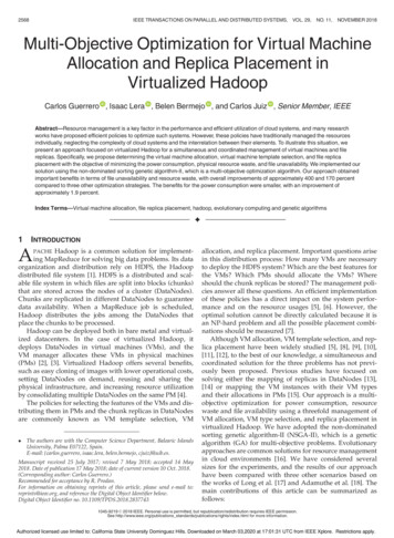
2572IEEE TRANSACTIONS ON PARALLEL AND DISTRIBUTED SYSTEMS,VOL. 29, NO. 11,NOVEMBER 2018is the set of PMs with at least one VM storing the chunk. Thefirst term of the formula, pmFailpmi , represents the caseswhen the chunk replicas in the PM become unavailable dueto a failure in that PM. The second term, the inner multiplication, represents the cases when the chunk replicas inthe PM become unavailabledue to failures in all the VMsQthat contain them: vmn 2A vmFailvmn , where A ¼ VMðbux Þ\fvmn j allocationðvmn Þ ¼ pmi g, considering VMðbux Þ ¼ fvmn jplacementðbux ½r Þ ! vmn 8bux ½r 2 fbux g as the set of VMs containing all the replicas of a chunk.3.5 Optimization FormulationThe objective of the optimization is to minimize file unavailability, power consumption and the waste of resources in avirtualized Hadoop. The decision variables, i.e., the elements to be managed, are the allocation of the VMs, theselection of the VM templates, the number of VM instances,and the placement of the replicas. The problem is formallydefined as determiningjVMj(18)vmtypeðvmn Þ 8 vmn 2 VM(19)allocationðvmn Þ 8 vmn 2 VM(20)placementðfbux ½r Þ; 8 fbux ½r 2 fbux ;8 fbux 2 fbu ; 8 fbu 2 HDFS;(21)by minimizingXResourceWasteðpmi Þ(22)pmi 2PMXPowConsðpmi Þ(23)Unavailabilityðfu Þ;(24)pmi 2PMXfu 2HDFSsubject to the definition offSizefu ; 8 fbu 2 HDFS(25)fbSizefu ; 8 fbu 2 HDFS;(26)and subject to the constraints in Equations (4), (5), and (6).This problem has jPMjjVMj possible allocations of VMs,ujVMjjffbx ½r gj possible placements of chunk replicas withjVMTypej different VM templates, and a variable and undetermined value for jVMj. It is an NP-hard problem since theevaluation of all the solutions is not approachable.4GENETIC ALGORITHM PROPOSALWe propose using the non-dominated sorting genetic algorithm-II to solve our multi-objective optimization problem.Genetic algorithms (GAs) are metaheuristic approaches forsolving NP-hard optimizations [40], [41], and NSGA-II is oneof the most common algorithms when the optimization hasmultiple objectives to minimize [42]. In the field of GA andthroughout this manuscript, the following terms are usedFig. 1. Example of chromosome representation.indistinctly: solution, chromosome, and individual; set of solutions and population; algorithm iteration and generation;and offspring, next population, and next algorithm iteration.The implementation of a GA involves defining the chromosomes, the fitness function, the crossover and mutationoperators, the selection operator, the replacement operator(offspring generation), and the execution settings. However,NSGA-II sets the selection and replacement operators, andit defines the fitness function as a vector that includes all theobjective functions. The details of NSGA-II can be found inthe original article [43] or in related works regardingresource management [44], [45]. The following sectionsexplain the implementation details that are not preset byNSGA-II.4.1 Chromosome RepresentationIn our case, the individuals of the population represent VMallocation, VM type selection, and replica placement, considering a fixed number of replicas and a variable numberof VMs. We represent each individual with two arrays: thevm-chromosome (C vm ) for the allocationðÞ and vmtypeðÞrelationships and the block-chromosome (C block ) for theplacementðÞ relationship. Fig. 1 shows an example with twoPMs, five VMs, two VM template types, and 12 replicas.The vm-chromosome C vm is a two-dimensional array inwhich the column indices represent the VMs, the values ofthe first row (allocation) indicate the PM where the VM isallocated, and the values of the second row (template type)indicate the template for the VM. The length of the vm-chromosome can change between solutions since there will besolutions with different numbers of VMs [46].The block-chromosome is an array where the indices represent the replicas in the system (bxu ½r ) and the positionscontain the VM where the replica is stored. This chromosome has a fixed length since the chunk size (fbSizefu ) andthe replication factor (fRfu ) are equal and constant for allthe files, and it is known before the optimization process.4.2 Crossover and Mutation OperatorsGAs are based on the idea of biological evolution, where thehighest qualified individuals, chosen by natural selection, aremated to obtain an offspring with the best features of bothparents. In this evolution, three aspects are essential: theselection of the individuals, their mating, and randomAuthorized licensed use limited to: California State University Dominguez Hills. Downloaded on March 03,2020 at 17:01:31 UTC from IEEE Xplore. Restrictions apply.
GUERRERO ET AL.: MULTI-OBJECTIVE OPTIMIZATION FOR VIRTUAL MACHINE ALLOCATION AND REPLICA PLACEMENT IN.2573combining the left piece of one parent with the right pieceof the other. Similarly, the second child is generated withthe remaining pieces. Fig. 2a shows an example of this firstphase of the crossover operator.The second phase of the crossover is more complex sincethe combination of the block-chromosomes results in solutions with replicas allocated in VMs from both fathers. Consequently, all the VMs referenced from the new blockchromosome should be incorporated in the resulting vmchromosome. Fig. 2b illustrates an example with the cuttingpoint placed in position 3. In this example, the new blockchromosome of the first child results in placing all the replicas in VMs 0, 1, 2, and 3 from the first parent and VMs a, b,and d from the second. Consequently, the vm-chromosomeis generated by the concatenation of positions 0, 1, 2, and 3of the vm-chromosome from the first father (dark gray positions in the vm-chromosome) and positions a, b, and d fromthe second (light gray positions).Formally, we define the block one cutting-point crossoversimilar to the splitting operation between two parents’ blockvmblockvmblock; Cf1g and Cf2 ¼ fCf2; Cf2g,chromosomes, Cf1 ¼ fCf1and one uniformly random value, j. The block-chromosomesof the new individuals are generated from the concatenationblock¼of the opposite segments of both parents split by j: Cc1blockblockblockblockblockblockCf1½0::j kCf2½j þ 1::jCf2j 1 and Cc2¼ Cf2½0::j kCf1½jþFig. 2. Example of the two phases of the crossover operator.changes in the offspring. In GA, these aspects are respectivelytranslated into selection, crossover and mutation operators.The crossover operator defines how two parent solutionsare combined to obtain two evolved children. Since we aredealing with three decision variables (vm allocation, vmtemplate selection, and replica placement), the crossover issequentially divided into a first phase where the crossoverof the vm-chromosome is performed over the allocation andtemplate-type arrays and a second phase for the crossoverof the block-chromosome. We use one cutting-point crossover operator in both cases. This operator generates one random cutting point that splits the chromosomes into twopieces. Children’s chromosomes are generated by combining the opposite pieces from both parents [47].The one-point operator for variable chromosome lengthis applied to the vm-allocation [48]: one random number isgenerated between 0 and the minimum length of bothparents’ chromosomes, and it splits the allocation and template arrays into two pieces. The first child is generated byblock1::jCf1j 1 . The vm-chromosomes are obtained from joining the genes of the parents corresponding to the VMs thatare contained in the resulting block-chromosome. Considerblock½n Þ, the VM gene of the corresponding fathering Gvmp ðCcwhere the block Ccblock ½n of the corresponding child is stored,the vm-machine chromosomes of the children can be definedvmblockblockvm¼ fGvm½n Þ 8 Ccblock ½n 2 Cc1g and Cc2¼as Cc1p ðCcvmblockblockblockfGp ðCc ½n Þ 8 Cc ½n 2 Cc2 g.Mutation operators generate random changes in thechromosome
Hadoop can be deployed both in bare metal and virtual-ized datacenters. In the case of virtualized Hadoop, it deploys DataNodes in virtual machines (VMs), and the VM manager allocates these VMs in physical machines (PMs) [2], [3]. Virtualized Hadoop offers several benefits, such as easy cloning of images with lower operational costs,