Transcription
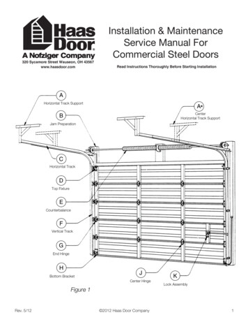
Installation & MaintenanceService Manual ForCommercial Steel Doors320 Sycamore Street Wauseon, OH 43567www.haasdoor.comRev. 5/12Read Instructions Thoroughly Before Starting Installation 2012 Haas Door Company1
Haas Door Commercial Instruction ManualOPENING PREPARATIONNote : All framing materials must be providedby building contractor or installer.Figure 2Some large doorsmay require additionalpad or pads located offcenter to accommodateauxiliary bearings.WSWSAll vertical jambsand pads regardlessof type, must extendto top of headroomrequirement.WWOpening HeightBSteelChannelS2X6Wood JambsOpening WidthSection “W”Interior ElevationS3”Min.Steel JambsSection “S”STEP 1 INSTALLATION OF DOORCheck the size of door to be sure it is the same size as opening. Inspect the track and determine if you have reverse angle orbracket mount tracks. Note: bracket mount has individual j-brackets to attach track to jamb, reverse angle has a continuousangle to attach track to jamb. Note: if door is supplied with reverse angle. The door should be 2” wider than opening.JCenterHingeBottomSectionGEnd Hingesee Figure 6on page 4for correcthinge numbersCenter StileWeatherstripFigure 3STEP 2RollerHCableBottom BracketDrill a 3 /16” diameterhole for this screwAttach hardware to bottom section with 1/4” x 3/4” hex head sheet metal screws (see Figure 3). If door requires struts (ubars) see Figure 8 on page 4.2 2012 Haas Door CompanyRev. 5/12
Haas Door Commercial Instruction ManualINSTALLATION OF VERTICAL TRACKSSTEP 3Position bottom section in center of the opening, allowing equal distance from each side of the opening.STEP 4Position left hand track over rollers as shown in Figure 4. Space track 1/2” from door as shown.Before attaching vertical track angle or brackets to jambs it must be plumb and parallel to door and raised to match leveling ofbottom door section.Attach vertical track angles to jambs by welding or by using 1/4” self drilling screws on steel jambs or 5/16" x 1 1/ 2” hexhead lag screws on wood jambs. If mounting directly to masonry, anchors are not supplied.Repeat above step for right hand track. (Note: Both tracks must be parallel for proper operation)Insert rollers into end hinges.Hook rollers into vertical track and swing endhinges onto door section as shown at left.Secure with fasteners provided.STEP 5Place #2 section on top of bottom section. Note: if door is supplied with cylinder lock, use section with lock holes punchedor drilled in it (see Step 19 on page 8).Attach hinges and rollers as shown in Figure 5. See hinge schedule Figure 6 on page 4 for correct placement of numberedhinges. If inside lock is supplied, see Figure 7.Rev. 5/12 2012 Haas Door Company3
Haas Door Commercial Instruction ManualHINGE SCHEDULESTEP 6Complete the remainder of the sections at this time. Topdoor section should only be installed after horizontal track orfull vertical track has been installed.Note: if door is supplied with full view aluminum section(s),attach hinges with 1/4” self drilling screws provided.STEP 7 SLIDE BOLT LOCKThe inside lock is installed on the end stile of the secondsection so the slide bolt rests against the top of one of therectangular engaging slots in the vertical track (see Figure 7).If door is supplied with cylinder lock, see page 8.STEP 8 U-BAR INSTALLATIONAll trusses (u-bars) except top section truss are attached withtech screws below hinges as shown in Figure 8. Top sectiontruss is located directly above the top roller brackets, securedat the ends with tech screws. Secure all trusses to centerstiles through existing holes utilizing tech screws.Note: Doors over 14’-2” wide require one truss per section.STEP 9 STANDARD LIFT TRACKAttach bearing brackets to the horizontal angles with 3/8” x3/4” bolts & nuts. Form rope loops to a convenient overheadstructural member & insert horizontal tracks through them,then attach bottom of the curved portions of track to the topof the vertical tracks at the splice brackets with 1/4” x 5/8”truss head machine screws & nuts. Head of machine screwsshould be to inside of the track (see Figure 9). Using a level,strike a plumb line from the inside of the splice bracket tothe inside of the horizontal angle on each side. Place outsideedges of bearing brackets against the plumb lines and attachbrackets securely to the wall (see Figure 9).4 2012 Haas Door CompanyRev. 5/12
Haas Door Commercial Instruction ManualSTEP 9a HI-LIFT TRACKSTEP 9b VERTICAL LIFT TRACKConnect vertical hi-lift track to top of existing vertical trackwith 1/4”x 5/8” truss head machine screws. Set track plumband fasten to jamb in the same manner as the vertical trackpreviously installed in Step 4. Attach bearing brackets to thehorizontal angles with 3/8” x 3/4” bolts & nuts. Form ropeloops to a convenient overhead structural member and inserthorizontal tracks through them, then attach bottom of thecurved portions of track to the top of the vertical tracks at thesplice brackets with 1/4” x 5/8” truss head machine screwsand nuts. Head of machine srews should be to inside of thetrack (see Figure 9a). Using a level, strike a plumb line fromthe inside ot the splice bracket to the inside of the horizontalangle on each side. Place outside edges of bearing bracketsagainst the plumb lines and attachbrackets securely to the wall(see Figure 9a).Place upper vertical track on top of lower vertical track.Plumb track and attach to wall in same manner as lowervertical tracks. Heads of machine screws should be to insideof the tracks as shown in Figure 9b. (Jamb fasteners mustbe installed with no more than 48” between each fastener.)Now set bearing brackets against the plumb lines and attachbrackets securely to the track and wall.STEP 10HORIZONTAL TRACK SUPPORT STEP 11 TOP BRACKETSReplace temporary support hangers with steel support angle(not supplied). Install sway braces only after checking thehorizontal track with a tape measure or spacing bar to verifythat they are parallel. Important: steel support or other meansmust be strong enough to support full door weight and mustbe attached to a structurally sound member.Note: a center horizontal track support is required for doorslarger than 12’-1” in height (see Figure 1 Item A on page 1).Rev. 5/12Place top section in position. With rollers inserted in thesleeves of top roller brackets, bolt brackets to sectionthrough holes provided, utilizing self-tapping screws. Adjustbracket slide so top section is perfectly vertical and tightenadjusting bolt securely. Attach top leaves of hinges from thepreceding section. Check tracks for proper clearance andpermanently secure all fasteners. 2012 Haas Door Company5
Haas Door Commercial Instruction ManualWARNING:Installing torsion springs can be a dangerous procedure and should only be performed by qualified door service personnel.Do not attempt installation without proper tools and until reading and understanding the following instructions.STEP 12 COUNTERBALANCE INSTALLATIONDetermine what type of spring assembly you have as shown in figures 12, 13, 14 or 15.STEP 13Place the center support bracket and the bearing on the axles as shown in Figure 16 (bearing sits inside spring fitting). Boltspring fitting(s) to center support bracket (see Figure 16 or 17) using 3/8” dia. x 1 1/2” hex head bolts. Slide a cable drumon both ends of shaft. Be sure correct hand drum is used (see Figures 12 thru 15). Slide bearing on each shaft end if notalready bolted to track.6 2012 Haas Door CompanyRev. 5/12
Haas Door Commercial Instruction ManualSTEP 14Raise the shaft assembly over the door. If 2 piece shaft with coupling is supplied, raise half the total shaft at a time. Rest theend(s) of shaft on the horizontal track angle.See Figure 19 For coupling installation.STEP 15Locate and attach spring bearing plates/center support bracket to mountlng pads (not supplied). See Figure 2 for wood orsteel frame (jambs) . Mount spring brackets to structural member of building of sufficient size to withstand spring(s) torque.When mounting springs on pads, keep in mind that springs grow in length when wound. Allow at least 5” space betweenspring fitting and cable drum. If mounting the center support bracket to wood, use (2) 5/16” x 1 5/8” long hex head lags foreach bracket. For steel jambs use (2) 3/8” x 1 1/2” hex head bolts. If mountlng directly to concrete use (2) 5/16” dia thrubolts or threaded rods (not supplied).STEP 16 ATTACHING THE CABLESThread each cable between the axle and wall. Then insert each cable into the entry slot of each drum. Wind the excess cableon the drum, then slide the drum against the bearing plate and tighten the two set screws securing the drum to the shaft.Clamp a set of locking pliers with the jaws locked onto the shaft and the other end against the wall so that cable tension 0nthe drum is taut (no slack) and the shaft locked. Secure the remaining drum making sure both cables have equal tension andare taut (see Figure 20). If axle is a solid shaft use a 1/4” key for both drums.STEP #17Before going to Step 18. Be sure door is in locked position. If no lock is supplied, place a clamp in both tracks of door directlyabove a roller to make sure door can not be raised at this tlme.STEP # 18 WINDING SPRING (see Figure 21)Note: garage door springs can cause serious injury if not handled properly. Before winding the springs, make sure the lock isengaged in the “locked” position. This will prevent the door from raising up by itself in the event the springs are over woundor are too strong . Use two cold rolled steel rods approximately 18” long and the same diameter as the holes in the windingcones (winding rods not furnished) 1/2” dia. for 1 3/4” & 2 5/8” springs and 5/8” dia. for larger springs. Do not use undersizedrods or other tools to wind springs. For your safety, position yourself on a sturdy ladder so that winding cone is either to yourright or to your left. Never stand directly in front of winding cones or winding bars. With one hand, insert one winding rod allthe way into the hole of the winding cone and wind the spring up one-quarter turn. With your other hand, insert the secondwinding bar into the next hole, remove the upper winding bar and then take another one-quarter turn. Proceed in this manner until you have made all the required number of turns. The number of turns are indicated on the spring tag attached tothe spring assembly. For example, if the tag says “wind spring 7 turns, 7 x 4 28 one-quarter turns are required to balance.Note: each complete turn will cause the chalk line to make one spiral. After the requred number of 1/4 turns have been made,tighten both set screws in the winding cone to secure it to the shaft before removing the winding bars. Repeat this procedurefor each spring, then locking pliers can be removed. Attach one red warning label to spring.Rev. 5/12 2012 Haas Door Company7
Haas Door Commercial Instruction ManualSTEP 19 CYLINDER LOCK INSTALLATIONIf lock cylinder is supplied, install in lock section as shown in the exploded view (see Figure 22).STEP #20 LIFT HANDLESInstall lift handle(s) on bottom section with 1/4” - 20 nuts andbolts supplied (as shown in fig. # 23).MAINTENANCE & CAUTIONSRecommended Service: lubricate rollers with a light oil as required. Check and tighten all nuts, bolts and screws annually.(This may be required more frequently for high usage doors.)Haas Door recommends servicing any part of the counterbalance system including springs, drums cables, bearing brackets,and bottom corner brackets where cable is attached be performed by qualified door service personnel only (see notice below).Important Safety Notice: Operate door only when properly adjusted and free of obstructions. Door is under extreme springtension. Repairs and adjustments, especially to cables and spring assembly, can be hazardous and should be performed byqualifled door service personnel only.Do not permit children to play with garage door or electric controls.If door is now, or later becomes, electrically operated, pull down rope must be removed.Avoid standing in open doorway or walking thru doorway while electrically operated door is moving.Should door become hard to operate or completely inoperative, it is recommended that a qualified door agency be contacted.The notice above has been approved and recommended by the National Association of Garage Door Manufacturers (NAGDM).8 2012 Haas Door CompanyRev. 5/12
Installation & Maintenance Service Manual For Commercial Steel Doors 320 Sycamore Street Wauseon, OH 43567 www.haasdoor.com Read Instructions Thoroughly Before